EP0098656B1 - Dispositif de mise à la terre - Google Patents
Dispositif de mise à la terre Download PDFInfo
- Publication number
- EP0098656B1 EP0098656B1 EP83200976A EP83200976A EP0098656B1 EP 0098656 B1 EP0098656 B1 EP 0098656B1 EP 83200976 A EP83200976 A EP 83200976A EP 83200976 A EP83200976 A EP 83200976A EP 0098656 B1 EP0098656 B1 EP 0098656B1
- Authority
- EP
- European Patent Office
- Prior art keywords
- conductor
- plane
- anyone
- earth terminal
- strip
- Prior art date
- Legal status (The legal status is an assumption and is not a legal conclusion. Google has not performed a legal analysis and makes no representation as to the accuracy of the status listed.)
- Expired
Links
- 239000004020 conductor Substances 0.000 claims description 29
- 239000011810 insulating material Substances 0.000 claims description 2
- 230000003472 neutralizing effect Effects 0.000 abstract 1
- JAPMJSVZDUYFKL-UHFFFAOYSA-N C1C2C1CCC2 Chemical compound C1C2C1CCC2 JAPMJSVZDUYFKL-UHFFFAOYSA-N 0.000 description 1
- 239000003673 groundwater Substances 0.000 description 1
- 230000037431 insertion Effects 0.000 description 1
- 238000003780 insertion Methods 0.000 description 1
- 239000002184 metal Substances 0.000 description 1
Images

Classifications
-
- A—HUMAN NECESSITIES
- A61—MEDICAL OR VETERINARY SCIENCE; HYGIENE
- A61N—ELECTROTHERAPY; MAGNETOTHERAPY; RADIATION THERAPY; ULTRASOUND THERAPY
- A61N1/00—Electrotherapy; Circuits therefor
- A61N1/16—Screening or neutralising undesirable influences from or using, atmospheric or terrestrial radiation or fields
Definitions
- the invention relates to an earthing device comprising an elongate electrical conductor bent in one plane in a symmetrical fashion such that its ends are spaced apart by a small distance.
- Such a device is known from GB-A-322 485.
- the electrical conductor forming part of this prior art device is carried by an insulating support means.
- the device according to the invention is characterized in that the middle of the conductor is connected with an earthing terminal.
- positioning means for arranging the plane of the conductor in a substantially horizontal position.
- the positioning means are constructed in the form of a ground pin fastened to the earth terminal and to be inserted into the ground in a position substantially perpendicular to the plane of the conductor.
- the device embodying the invention can be carried on the body.
- it may be provided with an electrically conductive carrying chain connected with the earth terminal.
- This carrying chain should be in contact with the skin.
- even slight conductivity is sufficient in view of the extremely weak electric currents involved. From practical experience it has been found that even poorly conductive rubber soles have a conductive power which is sufficient for satisfactory operation of the device embodying the invention.
- a device embodying the invention It should be noted that a device embodying the invention. It should be noted that a device embodying the invention carried around the neck will occupy a more or less vertical position so that no optimum results are ensured. In view thereof it is preferred to carry the device in a substantially horizontal position on the body. Particularly suitable thereto are the shoulders and the feet.
- the strip or wire may be made of metal. Lighter and cheaper may be the variant in which the conductor is a strip or wire made of electrical insulating material coated with an electrically conductive layer.
- a very important enlargement of the working zone is obtained by a variant in which the ends of the conductor are connected with the earth terminal by means of electric conductors which may be provided with an insulating sheath.
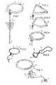
- Fig. 1 shows a device 1 embodying the invention.
- This device 1 comprises an electrically conductive wire 2, to the middle of which is fastened an earth terminal 3.
- an earth terminal 3 To the earth terminal 3 is secured a ground pin 4.
- the latter has a tip 5 at the lower end so that the pin 4 can be readily inserted into the ground in a manner such that the ground pin 4 comes into contact with humid earth or even ground water.
- the conductor 2 is annularly bent so that it is located in one plane, whilst its ends 7 are at a small distance from one another.
- the plane of the conductor 2 is substantially normal to the direction of length of the ground pin 4 so that the conductor 2 can be readily set in a horizontal position.
- Fig. 2 shows a second embodiment of the invention.
- a strip 8 has a rectangular cross-section in contrast to the first embodiment of fig. 1 in which the conductor 2 has a circular cross-section, whilst the shape of the strip is substantially a triangle with rounded-off corners.
- an earth connection 9 with the ground pin 4.
- the ends of the strip 8 are slightly spaced apart.
- the third embodiment shown in fig. 3 comprises a strip 10 of pentagonal shape. To one corner is fastened the earth connection 9 with the ground pin 10. On the opposite side in the middle the ends of the strip 10 are slightly spaced apart. The cross-section of the strip 10 is generally rectangular.
- Fig. 4 shows a fourth embodiment.
- a round wire 11 has an octogonal shape.
- the earth terminal 3 is arranged with the ground pin 4 like in the embodiment of fig. 1, whilst on the opposite side the ends of the wire 11 are located at a small distance from one another.
- Fig. 5 shows a fifth, simple embodiment in which the conductor 2 is provided in the middle with an earth terminal 12 to which a ground lead 13 is conductively fastened.
- this simple embodiment has to be disposed in an insulated manner. Only the ground lead 13 has to be connected with the ground.
- FIG. 6 shows an elegant embodiment of the device in accordance with the invention.
- a conductive carrying chain 14 serves to carry the conductive ring 15, which is conductively connected in the middle with the chain 14.
- Fig. 7 shows a device 17 having an annular conductor 2 to the middle of which is secured a conductive carrying rod 18, the lower part of which is carried by a relatively heavy foot 19.
- an earthing wire 20 To the carrying rod 18 is fastened an earthing wire 20, to the free end of which is secured an earthing plug 21.
- This earthing plug has the same shape as a conventional plug with earthed rim 22, but it is not provided with pins so that after insertion into a normal wall mains connector it can solely serve for earthing purposes.
- All embodiments described above are constructed so that the surfaces of the ends of the strip or wire are flat and substantially coincide with the plane of symmetry of the conductive ring.
- Fig. 8 shows a variant differing from the embodiment of fig. 1 by the presence of two conductors 23, 24 by which the ends 7 are conductively connected with the earth terminal 3.
- Fig. 9 shows an embodiment in which a ring 25 can be carried by means of a chain 26 on the body like in the embodiment of fig. 6, whilst in accordance with the embodiment of fig. 8 the ends 26 are connected with the middle of the ring 25 by means of conductors 29 provided with an insulating sheath 28.
- the operation of this embodiment is fully analogous to that of fig. 8.
- Fig. 10 is a schematic representation of the active zone of the devices without electric connection between the ends and the earth terminal.
- the curve 28 indicated the boundary of the operative range of the device of fig. 1. It is inserted into the ground 29.
- the device 1 is operative along a depth of, for example, 5 metres, whilst the radius of the active zone at the surface may be about 20 metres.
- the curve 31 indicates the boundary of the active zone of the device 30 of fig. 8. From fig. 10, drawn approximately to scale, it appears that the activity in depth is enlarged by 100%, whilst the active radius at ground surface has increased by about 30%.
Landscapes
- Health & Medical Sciences (AREA)
- Engineering & Computer Science (AREA)
- Biomedical Technology (AREA)
- Nuclear Medicine, Radiotherapy & Molecular Imaging (AREA)
- Radiology & Medical Imaging (AREA)
- Life Sciences & Earth Sciences (AREA)
- Animal Behavior & Ethology (AREA)
- General Health & Medical Sciences (AREA)
- Public Health (AREA)
- Veterinary Medicine (AREA)
- Transplanting Machines (AREA)
- Control Of Motors That Do Not Use Commutators (AREA)
- Waveguide Aerials (AREA)
- Elimination Of Static Electricity (AREA)
- Electrotherapy Devices (AREA)
- Multi-Conductor Connections (AREA)
- Portable Outdoor Equipment (AREA)
- Cephalosporin Compounds (AREA)
- Water Treatment By Electricity Or Magnetism (AREA)
Claims (8)
Priority Applications (1)
| Application Number | Priority Date | Filing Date | Title |
|---|---|---|---|
| AT83200976T ATE36810T1 (de) | 1982-07-01 | 1983-06-30 | Erdungsvorrichtung. |
Applications Claiming Priority (2)
| Application Number | Priority Date | Filing Date | Title |
|---|---|---|---|
| NL8202664A NL8202664A (nl) | 1982-07-01 | 1982-07-01 | Inrichting voor het neutraliseren van biologisch actieve velden. |
| NL8202664 | 1982-07-01 |
Publications (3)
| Publication Number | Publication Date |
|---|---|
| EP0098656A2 EP0098656A2 (fr) | 1984-01-18 |
| EP0098656A3 EP0098656A3 (en) | 1985-01-23 |
| EP0098656B1 true EP0098656B1 (fr) | 1988-08-31 |
Family
ID=19839959
Family Applications (1)
| Application Number | Title | Priority Date | Filing Date |
|---|---|---|---|
| EP83200976A Expired EP0098656B1 (fr) | 1982-07-01 | 1983-06-30 | Dispositif de mise à la terre |
Country Status (5)
| Country | Link |
|---|---|
| EP (1) | EP0098656B1 (fr) |
| AT (1) | ATE36810T1 (fr) |
| CA (1) | CA1208298A (fr) |
| DE (1) | DE3377862D1 (fr) |
| NL (1) | NL8202664A (fr) |
Families Citing this family (4)
| Publication number | Priority date | Publication date | Assignee | Title |
|---|---|---|---|---|
| DE3541480A1 (de) * | 1985-11-23 | 1987-05-27 | Stiftung Ordo | Schutzgeraet |
| DE3601743A1 (de) * | 1986-01-22 | 1987-07-23 | Hartmut Dipl Ing Haberland | Anordnung zur abschirmung von gitternetzstrahlungen |
| FR2667436B1 (fr) * | 1990-09-28 | 1992-12-11 | Deoux Pierre | Dispositif anti-induction. |
| IT1270810B (it) * | 1993-09-09 | 1997-05-07 | Bruno Schirato | Dispositivo per la protezione del corpo umano dall'influenza di campi elettromagnetici esterni |
Family Cites Families (8)
| Publication number | Priority date | Publication date | Assignee | Title |
|---|---|---|---|---|
| GB322485A (en) * | 1928-07-31 | 1929-12-02 | Georges Lakhovsky | Improvements in or relating to apparatus for collecting electrical oscillations |
| DE526039C (de) * | 1928-10-16 | 1931-06-03 | Gustav Freiherr Von Pohl | Einrichtung zur Verhinderung von Schaeden durch von Erdstroemen herruehrende Ausstrahlungen |
| NL24104C (fr) * | 1929-01-29 | |||
| GB650284A (en) * | 1948-06-18 | 1951-02-21 | Johannes Christen | Improvements in apparatus responsive to cosmic rays |
| BE508340A (fr) * | 1949-07-19 | |||
| FR1375858A (fr) * | 1963-08-29 | 1964-10-23 | Dispositif filtrant notamment pour les radiations cosmiques | |
| FR1384763A (fr) * | 1963-11-26 | 1965-01-08 | Dispositif d'activation | |
| FR1417864A (fr) * | 1964-12-19 | 1965-11-12 | Appareil de protection contre les ondes telluriques d'origine aquatique |
-
1982
- 1982-07-01 NL NL8202664A patent/NL8202664A/nl not_active Application Discontinuation
-
1983
- 1983-06-23 CA CA000431089A patent/CA1208298A/fr not_active Expired
- 1983-06-30 EP EP83200976A patent/EP0098656B1/fr not_active Expired
- 1983-06-30 AT AT83200976T patent/ATE36810T1/de not_active IP Right Cessation
- 1983-06-30 DE DE8383200976T patent/DE3377862D1/de not_active Expired
Also Published As
| Publication number | Publication date |
|---|---|
| DE3377862D1 (en) | 1988-10-06 |
| ATE36810T1 (de) | 1988-09-15 |
| CA1208298A (fr) | 1986-07-22 |
| NL8202664A (nl) | 1984-02-01 |
| EP0098656A3 (en) | 1985-01-23 |
| EP0098656A2 (fr) | 1984-01-18 |
Similar Documents
| Publication | Publication Date | Title |
|---|---|---|
| ATE17394T1 (de) | Elektrisch stromfuehrender flexibler schlauch. | |
| SE8603203L (sv) | Roterbar elektrisk anslutningsanordning for spirallindade telefonsladdar | |
| ES470097A1 (es) | Un dispositivo conectador mejorado para la transmision de una senal electrica | |
| ATE11978T1 (de) | Steckverbinder fuer ein flaches mehrleiterkabel. | |
| GB1495162A (en) | Surgical electrode | |
| SE8103573L (sv) | Elektrodaggregat | |
| ES428471A1 (es) | Perfeccionamientos introducidos en cables electricos blin- dados. | |
| GB1235600A (en) | Improvements in and relating to electrical contact terminals | |
| DK67283D0 (da) | Elektrisk forbindelsesorgan og forbindelsesaggregat | |
| EP0098656B1 (fr) | Dispositif de mise à la terre | |
| EP0031869A3 (en) | Transition between a coaxial cable and a multipolar pluggable connector | |
| US3246282A (en) | Plug receptacle and connector assembly | |
| GB9002172D0 (en) | Electrical connector | |
| US4174144A (en) | Housing for an electrical terminal | |
| JPS5246488A (en) | Electric connector | |
| HK13586A (en) | Contact device for a multiconductor cable | |
| CA1064126A (fr) | Boitier pour borne electrique | |
| JPS5624774A (en) | Electric connector | |
| EP0975050A3 (fr) | Connecteur électrique pour fils/câble | |
| BR8101393A (pt) | Contacto eletrico e conector eletrico | |
| US3441899A (en) | Electrical connector | |
| KR102921266B1 (ko) | 어싱 가이드 구조체 | |
| GB1296550A (fr) | ||
| JPS5551606A (en) | Tire with earth connection | |
| US2716227A (en) | Electrical connector for attachment plugs having means to attach conductors thereto |
Legal Events
| Date | Code | Title | Description |
|---|---|---|---|
| PUAI | Public reference made under article 153(3) epc to a published international application that has entered the european phase |
Free format text: ORIGINAL CODE: 0009012 |
|
| AK | Designated contracting states |
Designated state(s): AT BE CH DE FR GB IT LI LU NL SE |
|
| PUAL | Search report despatched |
Free format text: ORIGINAL CODE: 0009013 |
|
| AK | Designated contracting states |
Designated state(s): AT BE CH DE FR GB IT LI LU NL SE |
|
| 17P | Request for examination filed |
Effective date: 19850626 |
|
| 17Q | First examination report despatched |
Effective date: 19870318 |
|
| ITF | It: translation for a ep patent filed | ||
| GRAA | (expected) grant |
Free format text: ORIGINAL CODE: 0009210 |
|
| AK | Designated contracting states |
Kind code of ref document: B1 Designated state(s): AT BE CH DE FR GB IT LI LU NL SE |
|
| REF | Corresponds to: |
Ref document number: 36810 Country of ref document: AT Date of ref document: 19880915 Kind code of ref document: T |
|
| REF | Corresponds to: |
Ref document number: 3377862 Country of ref document: DE Date of ref document: 19881006 |
|
| ET | Fr: translation filed | ||
| PGFP | Annual fee paid to national office [announced via postgrant information from national office to epo] |
Ref country code: SE Payment date: 19890606 Year of fee payment: 7 |
|
| PGFP | Annual fee paid to national office [announced via postgrant information from national office to epo] |
Ref country code: FR Payment date: 19890609 Year of fee payment: 7 |
|
| PGFP | Annual fee paid to national office [announced via postgrant information from national office to epo] |
Ref country code: AT Payment date: 19890612 Year of fee payment: 7 |
|
| PLBE | No opposition filed within time limit |
Free format text: ORIGINAL CODE: 0009261 |
|
| STAA | Information on the status of an ep patent application or granted ep patent |
Free format text: STATUS: NO OPPOSITION FILED WITHIN TIME LIMIT |
|
| ITTA | It: last paid annual fee | ||
| 26N | No opposition filed | ||
| PG25 | Lapsed in a contracting state [announced via postgrant information from national office to epo] |
Ref country code: AT Effective date: 19900630 |
|
| PG25 | Lapsed in a contracting state [announced via postgrant information from national office to epo] |
Ref country code: SE Effective date: 19900701 |
|
| PG25 | Lapsed in a contracting state [announced via postgrant information from national office to epo] |
Ref country code: FR Effective date: 19910228 |
|
| REG | Reference to a national code |
Ref country code: FR Ref legal event code: ST |
|
| PGFP | Annual fee paid to national office [announced via postgrant information from national office to epo] |
Ref country code: GB Payment date: 19920716 Year of fee payment: 10 |
|
| PGFP | Annual fee paid to national office [announced via postgrant information from national office to epo] |
Ref country code: CH Payment date: 19920929 Year of fee payment: 10 |
|
| PG25 | Lapsed in a contracting state [announced via postgrant information from national office to epo] |
Ref country code: LI Effective date: 19930630 Ref country code: GB Effective date: 19930630 Ref country code: CH Effective date: 19930630 |
|
| EPTA | Lu: last paid annual fee | ||
| GBPC | Gb: european patent ceased through non-payment of renewal fee |
Effective date: 19930630 |
|
| REG | Reference to a national code |
Ref country code: CH Ref legal event code: PL |
|
| PGFP | Annual fee paid to national office [announced via postgrant information from national office to epo] |
Ref country code: DE Payment date: 19940729 Year of fee payment: 12 |
|
| PGFP | Annual fee paid to national office [announced via postgrant information from national office to epo] |
Ref country code: LU Payment date: 19940801 Year of fee payment: 12 |
|
| EUG | Se: european patent has lapsed |
Ref document number: 83200976.5 Effective date: 19910402 |
|
| PG25 | Lapsed in a contracting state [announced via postgrant information from national office to epo] |
Ref country code: LU Free format text: LAPSE BECAUSE OF NON-PAYMENT OF DUE FEES Effective date: 19950630 |
|
| PG25 | Lapsed in a contracting state [announced via postgrant information from national office to epo] |
Ref country code: DE Effective date: 19960301 |
|
| PGFP | Annual fee paid to national office [announced via postgrant information from national office to epo] |
Ref country code: BE Payment date: 19990728 Year of fee payment: 17 |
|
| PG25 | Lapsed in a contracting state [announced via postgrant information from national office to epo] |
Ref country code: BE Free format text: LAPSE BECAUSE OF NON-PAYMENT OF DUE FEES Effective date: 20000630 |
|
| PGFP | Annual fee paid to national office [announced via postgrant information from national office to epo] |
Ref country code: NL Payment date: 20000630 Year of fee payment: 18 |
|
| BERE | Be: lapsed |
Owner name: GIERKINK ALPHONS JOHANNES HENDRIKUS Effective date: 20000630 |
|
| PG25 | Lapsed in a contracting state [announced via postgrant information from national office to epo] |
Ref country code: NL Free format text: LAPSE BECAUSE OF NON-PAYMENT OF DUE FEES Effective date: 20020101 |
|
| NLV4 | Nl: lapsed or anulled due to non-payment of the annual fee |
Effective date: 20020101 |