EP0098719A2 - Hydraulisches Ventil mit doppelter Signalrückführung - Google Patents
Hydraulisches Ventil mit doppelter Signalrückführung Download PDFInfo
- Publication number
- EP0098719A2 EP0098719A2 EP83303669A EP83303669A EP0098719A2 EP 0098719 A2 EP0098719 A2 EP 0098719A2 EP 83303669 A EP83303669 A EP 83303669A EP 83303669 A EP83303669 A EP 83303669A EP 0098719 A2 EP0098719 A2 EP 0098719A2
- Authority
- EP
- European Patent Office
- Prior art keywords
- flow
- valve
- feedback
- signal
- load
- Prior art date
- Legal status (The legal status is an assumption and is not a legal conclusion. Google has not performed a legal analysis and makes no representation as to the accuracy of the status listed.)
- Granted
Links
Images

Classifications
-
- F—MECHANICAL ENGINEERING; LIGHTING; HEATING; WEAPONS; BLASTING
- F15—FLUID-PRESSURE ACTUATORS; HYDRAULICS OR PNEUMATICS IN GENERAL
- F15B—SYSTEMS ACTING BY MEANS OF FLUIDS IN GENERAL; FLUID-PRESSURE ACTUATORS, e.g. SERVOMOTORS; DETAILS OF FLUID-PRESSURE SYSTEMS, NOT OTHERWISE PROVIDED FOR
- F15B13/00—Details of servomotor systems ; Valves for servomotor systems
- F15B13/16—Special measures for feedback, e.g. by a follow-up device
-
- Y—GENERAL TAGGING OF NEW TECHNOLOGICAL DEVELOPMENTS; GENERAL TAGGING OF CROSS-SECTIONAL TECHNOLOGIES SPANNING OVER SEVERAL SECTIONS OF THE IPC; TECHNICAL SUBJECTS COVERED BY FORMER USPC CROSS-REFERENCE ART COLLECTIONS [XRACs] AND DIGESTS
- Y10—TECHNICAL SUBJECTS COVERED BY FORMER USPC
- Y10T—TECHNICAL SUBJECTS COVERED BY FORMER US CLASSIFICATION
- Y10T137/00—Fluid handling
- Y10T137/8593—Systems
- Y10T137/86493—Multi-way valve unit
- Y10T137/86574—Supply and exhaust
- Y10T137/86582—Pilot-actuated
- Y10T137/86606—Common to plural valve motor chambers
-
- Y—GENERAL TAGGING OF NEW TECHNOLOGICAL DEVELOPMENTS; GENERAL TAGGING OF CROSS-SECTIONAL TECHNOLOGIES SPANNING OVER SEVERAL SECTIONS OF THE IPC; TECHNICAL SUBJECTS COVERED BY FORMER USPC CROSS-REFERENCE ART COLLECTIONS [XRACs] AND DIGESTS
- Y10—TECHNICAL SUBJECTS COVERED BY FORMER USPC
- Y10T—TECHNICAL SUBJECTS COVERED BY FORMER US CLASSIFICATION
- Y10T137/00—Fluid handling
- Y10T137/8593—Systems
- Y10T137/86493—Multi-way valve unit
- Y10T137/86574—Supply and exhaust
- Y10T137/86582—Pilot-actuated
- Y10T137/86614—Electric
Definitions
- This invention relates to feedback controlled hydraulic valves and feedback control arrangements for hydraulic valves.
- Hydraulic control valves with flow feedback control are known, for example from British Patent Specification No.1,335,042 which discloses a valve comprising a main valve, a pilot valve to operate the main valve, an electric force motor to set the pilot valve, and a flow sensing arrangement to generate and supply to the pilot valve a feedback pressure differential proportional to the rate of fluid flow through the main valve.
- the main valve and the pilot valve are both spool valves, with the setting of the pilot valve spool determining the relative magnitudes of two opposing control pressures applied across the main valve spool and hence the main valve spool setting.
- the pilot valve setting is determined by the resultant of the force applied to the pilot spool by the force motor, and the force due to the feedback pressure differential which is applied across the pilot spool.
- the feedback pressure differential is generated in the flow sensor which is, broadly speaking, a continuously variable orifice bounded by the periphery of a spring-loaded movable element and the adjacent internal wall of a throated fluid passage within which the movable element is located and which widens down stream from its region of narrowest cross-section.
- the spring-loaded element is urged in a down stream direction by the pressure differential generated as a result of fluid flowing through the flow restriction, and in an upstream direction by the restoring force of thesprin g which urges the element towards the region of narrowest cross-section.
- the electrical feedback signal may be derived either by converting the pressure differential into an electrical signal by means of a mechanical-to-electrical pressure transducer, or by measuring electrically the amount of displacement of the movable flow sensor element.
- the electrical feedback signal may be derived either by converting the pressure differential into an electrical signal by means of a mechanical-to-electrical pressure transducer, or by measuring electrically the amount of displacement of the movable flow sensor element.
- feedback of the pressure differential or of an electrical signal derived from it will be referred to hereinafter as pressure feedback and feedback of an electrical signal derived from measuring the displacement of the movable flow sensor element as displacement feedbacks.
- the first mode consists of the movable element becoming stuck in or near the narrowest region of the throat, and the second mode, which may be caused by failure of the return spring, of substantially unopposed movement into, and possible sticking of the movable element in or near, the widest region of the throat.
- the result is an incorrect feedback signal and consequential impairment or loss of control.
- the result may be a closing of the valve, an opening of the valve, or oscillation of the valve between the closed and the open states.
- the flow sensor orifice is, at least over most of the flow range, going to be larger than appropriate for the extant flow rate.
- the pressure differential resulting from a given flow rate is therefore below the correct value. This is seen by the valve as indicating insufficiently high flow, with the effect that flow is increased by further opening the main valve.
- the present invention aims to overcome, or at least mitigate, some of the effects of flow feedback failure and, in particular, the effects of flow feedback failure of the kind leading to excessive flow, to valve oscillations or to loss of control.
- a valve arrangement with flow feedback there are provided means to sense the position of the flow controlling valve member, and means to override the flow feedback if at any set flow a corresponding predetermined valve opening, as determined by the positioning of the valve member, does not result in a flow feedback signal indicating a sufficiently large flow.
- the flow through the valve will be the lower the higher the encountered load resistance or, put differently, the main valve opening required to obtain a desired flow to the load must be the greater, the greater the encountered load resistance.
- the present invention only allows the valve to open, for each desired flow rate, at most by a predetermined amount which corresponds to a maximum premissible load resistance.
- valve member is sensed electrically such as by variable resistance or inductive devices, for example.
- a comparator and switching circuit may be provided to compare the flow feedback signal with the positioning signal, and to switch control of the valve to whichever signal corresponds to the lower flow.
- positioning of the main stage flow control element may be measured electrically.
- the electrical signal so generated may then operate to reset the pilot stage to neutral, so preventing further movement of the valve member, in the event that the main valve has reached the predetermined opening.
- a further advantage accrues from the generally shorter response time of position sensing as compared to flow sensing.
- the invention By limiting the valve opening, and because of the faster response of position sensing, the invention will generally lead to a reduction in the tendency of the valve to over-shoot.
- the flow sensor will often be located close to the valve, some applications require that the flow sensor be located close to the load. In such a case, the flow feedback from each load will normally be through an electrical flow feedback signal. The greater separation of the flow sensor from the valve increases the likelihood of the electrical connection being broken.
- the position sensing means are mounted on the valve, and will usually form an integral part of the valve assembly, whereby there is less likelihood of interruption than with feedback from a remote flow sensor.
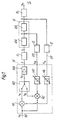
- a valve arrangement comprising a main valve 10, a pilot valve 11, a flow sensor 12, a position sensor 13 and electronic control circuitry 14.
- Flow Q through the main valve 10 is controlled by a signal g from the pilot valve 11. More precisely, the flow signal g controls the valve opening 10A by determining the position X of its flow controlling member, and the position X in turn determines the flow resistance lOB of, and hence the flow Q through, the valve 10.
- the pilot valve 11 receives from the circuit 14 an input current 1 which determines the pilot valve setting.
- the Flow Q from the main valve 10 to the load, such as an actuator 15, is measured by the flow sensor 12 whose output signal S Q on line 129 is proportional to the flow Q.
- the position X of the flow-controlling valve member within the main valve 10 is sensed by the position sensor 13 whose output signal S X on line 139 is proportional to the displacement of the valve member such as, for instance the main valve spool 101 in Figure 2.
- the electronic circuit 14 has an input receiving an electrical demand signal S proportional to the desired flow.
- the demand signal S D is applied to one input of each of two summing junctions 141 and 142 whose second inputs are respectively connected, via optional gain control circuits 146 and 147, to the output lines 129 of the flow sensor 12 and 139 of the position senscr 13.
- the respective output signals S A and S B of the summing junctions 141 and 142 are supplied as inputs to a compare and select circuit 143.
- the output signal S E of the circuit 143 is supplied to a power amplifier circuit 144 which supplies an input current 1, proportional to the signal S E , to the pilot valve 11.
- FIG. 2 there is shown a pilot-operated spool valve 10 arranged to control the magnitude and direction of the flow to and from the load 15, the valve member controlling the flow Q being the main valve spool 101.
- the valve member controlling the flow Q being the main valve spool 101.
- the spool position sensor 13 is mounted on the valve 10 adjoining one end of the main spool 101.
- a rod 102 provides a rigid link between the end of the spool 101 and a movable core 132 of the position sensor 13.
- the position sensor 13 is a commercially produced linear variable displacement transducer (LVDT) available for example, from E lektroteile GmBH, Uhldingen Muhlhofen, Federal Republic of Germany.
- LVDT linear variable displacement transducer
- the operation of the illustrated valve arrangement is as follows.
- the desired flow Q to the actuator 15 is determined by the demand signal S D , assumed for the purposes of explanation to be positive, on line 140.
- the flow feedback signal S Q is equal in magnitude but opposite in polarity to the demand signal S D . Consequently, the sum signal S A , and hence the error signal S E applied to the input of the amplifier 144, are practically zero.
- the position feedback signal S x also of negative polarity, on line 139 is arranged by adjustment of the gain and bias control circuits 146 and 147, or the like, to be equal to the flow feedback signal S Q only at a valve opening corresponding to a maximum permissible load.
- the signal S will be seen, under the assumed conditions to be less negative than the signal S Q , making the signal S B greater than zero. Indeed, under normal operating conditions and with normal loads, the signal S B will be appreciably greater than zero.
- the circuit 143 is a compare and select circuit which compares the sum signals S A and S B , and supplies whichever is the smaller as the error signal S E to the amplifier 144. Since the signal S D is coupled to both summing junctions 141 and 142, a change in the demand signal will not affect the relative magnitudes of the signals S A and S B . Variations in the load resistance lead to a variation of the sensed flow, and hence in a change in the sum signal S A . However, provided the gain and bias control circuits 146 and 147 are suitably adjusted, the signal S A will, under normal operating conditions, always remain smaller than the signal S B , although their relative magnitudes will be affected. For example, a minor increase in the load resistance will result in a reduction of the flow Q.
- the position signal S X will still be less negative than the flow signals S Q , and hence the sum signal S B will remain positive, while the flow signal S A will return from its smaller position value to zero as soon as the correct flow has been re-established.
- the compare and select circuit 143 will temporarily select the position feedback signal S as the apprcpriate feedback signal under saturation conditions, that is if a desired flow to the load has been set but due to the large load resistance the load has not yet begun to move.
- the position feedback will maintain the valve at an opening less than full until movement of the load commences. Movement of the load, of course, implies flow of fluid to the load and a reduction in the apparent load resistance.
- the circuit 143 restores control to the flow feedback loop.
- the valve opening is closer to the correct value, less time is needed to reach the correct opening.
- the position sensor 13 will permit a shift of the flow control element of the valve 10 only to a position corresponding to the maximum load, and this shift will normally be less than would result if only the flow feedback mechanism were employed, since the flow feedback mechanism is generally slower than the position feedback. The tendency to overshoot is thereby reduced.
- the flow sensor may be of any type other than the LVDT type illustrated, for example a pressure transducer, and the invention is equally applicable to a two-way valve as well as the four-way valve illustrated in Figure 2.
Landscapes
- Engineering & Computer Science (AREA)
- Physics & Mathematics (AREA)
- Fluid Mechanics (AREA)
- Mechanical Engineering (AREA)
- General Engineering & Computer Science (AREA)
- Servomotors (AREA)
Applications Claiming Priority (2)
| Application Number | Priority Date | Filing Date | Title |
|---|---|---|---|
| GB8219280 | 1982-07-02 | ||
| GB8219280 | 1982-07-02 |
Publications (3)
| Publication Number | Publication Date |
|---|---|
| EP0098719A2 true EP0098719A2 (de) | 1984-01-18 |
| EP0098719A3 EP0098719A3 (en) | 1984-08-01 |
| EP0098719B1 EP0098719B1 (de) | 1986-09-10 |
Family
ID=10531457
Family Applications (1)
| Application Number | Title | Priority Date | Filing Date |
|---|---|---|---|
| EP83303669A Expired EP0098719B1 (de) | 1982-07-02 | 1983-06-24 | Hydraulisches Ventil mit doppelter Signalrückführung |
Country Status (5)
| Country | Link |
|---|---|
| US (1) | US4635682A (de) |
| EP (1) | EP0098719B1 (de) |
| JP (1) | JPS5923105A (de) |
| AU (1) | AU1587183A (de) |
| DE (1) | DE3366068D1 (de) |
Cited By (13)
| Publication number | Priority date | Publication date | Assignee | Title |
|---|---|---|---|---|
| US4842162A (en) * | 1987-03-27 | 1989-06-27 | Nordson Corporation | Apparatus and method for dispensing fluid materials using position-dependent velocity feedback |
| US4907493A (en) * | 1986-04-03 | 1990-03-13 | Massey-Ferguson Services N. V. | Valve control system for hitch motor |
| US4922852A (en) * | 1986-10-30 | 1990-05-08 | Nordson Corporation | Apparatus for dispensing fluid materials |
| EP0342461A3 (en) * | 1988-05-14 | 1990-05-16 | Bodenseewerk Geratetechnik Gmbh | Triggering device with redundant controllers for a valve actuated by an electric motor |
| EP0370070A4 (en) * | 1988-05-17 | 1991-01-16 | Moog Inc. | Synthetisized flow-control servovalve |
| US4988015A (en) * | 1986-10-30 | 1991-01-29 | Nordson Corporation | Method for dispensing fluid materials |
| EP0439433A1 (de) * | 1990-01-23 | 1991-07-31 | IMI Norgren AG | Pneumatisches Schieberventil |
| US5054650A (en) * | 1986-10-30 | 1991-10-08 | Nordson Corporation | Method of compensating for changes in the flow characteristics of a dispensed fluid to maintain the volume of dispensed fluid at a setpoint |
| WO1992000480A1 (de) * | 1990-06-30 | 1992-01-09 | Robert Bosch Gmbh | Regelelektronik für solobetriebene magnetventile und für ventilkaskaden |
| US5240041A (en) * | 1989-12-28 | 1993-08-31 | Moog Inc. | Synthesized flow-control servovalve |
| EP0580852A4 (en) * | 1992-02-13 | 1994-08-17 | Johnson Service Co | Electronic pilot positioner |
| US5499745A (en) * | 1994-02-18 | 1996-03-19 | Nordson Corporation | Apparatus for mixing and dispensing two chemically reactive materials |
| EP4517107A1 (de) * | 2023-08-31 | 2025-03-05 | Illinois Tool Works Inc. | Dynamisches prüfsystem mit geschwindigkeitsregelung von einem hydraulischen stellantrieb |
Families Citing this family (9)
| Publication number | Priority date | Publication date | Assignee | Title |
|---|---|---|---|---|
| US5289388A (en) * | 1989-04-21 | 1994-02-22 | Vickers, Incorporated | Electrohydraulic control of a die casting machine |
| US5499647A (en) * | 1995-01-12 | 1996-03-19 | Mac Valves, Inc. | Method and valve assembly for controlling a pilot signal |
| US5526838A (en) * | 1995-01-12 | 1996-06-18 | Mac Valves, Inc. | Method and valve assembly for controlling a pilot signal |
| US6571757B1 (en) * | 2002-04-22 | 2003-06-03 | Borgwarner Inc. | Variable force solenoid with spool position feedback to control the position of a center mounted spool valve to control the phase angle of cam mounted phaser |
| US6792902B2 (en) * | 2002-04-22 | 2004-09-21 | Borgwarner Inc. | Externally mounted DPCS (differential pressure control system) with position sensor control to reduce frictional and magnetic hysteresis |
| KR100641393B1 (ko) * | 2004-12-07 | 2006-11-01 | 볼보 컨스트럭션 이키프먼트 홀딩 스웨덴 에이비 | 유압제어회로 및 유압제어방법 |
| CN101663492A (zh) * | 2007-02-22 | 2010-03-03 | 雷神萨科斯公司 | 第一级先导阀 |
| US20080257570A1 (en) * | 2007-04-17 | 2008-10-23 | Johnny Keplinger | Electronic draft control for semi-trailed implements |
| US20080257569A1 (en) * | 2007-04-17 | 2008-10-23 | Chris Foster | Electronic draft control for trailed implements |
Family Cites Families (14)
| Publication number | Priority date | Publication date | Assignee | Title |
|---|---|---|---|---|
| DE48004C (de) * | A. HlND in Wyke (York) England | Verfahren zur Herstellung von Salleisten bei Doppelsammtgeweben | ||
| US2929362A (en) * | 1954-08-26 | 1960-03-22 | Sanders Associates Inc | Differential hydraulic valve |
| DE1423906A1 (de) * | 1961-12-08 | 1969-01-30 | Siemens Ag | Durchflussregeleinrichtung |
| GB1335042A (en) * | 1970-01-05 | 1973-10-24 | Sperry Rand Ltd | Hydraulic actuator controls |
| US3699989A (en) * | 1970-06-18 | 1972-10-24 | Lummus Co | Feedback control apparatus |
| US3752189A (en) * | 1971-09-15 | 1973-08-14 | Moog Inc | Electrical feedback servovalve |
| GB1406326A (en) * | 1972-11-08 | 1975-09-17 | Sperry Rand Ltd | Hydraulic actuator controls disazo pigment |
| GB1462879A (en) * | 1973-10-10 | 1977-01-26 | Sperry Rand Ltd | Hydraulic actuator controls |
| DE2523600A1 (de) * | 1975-05-28 | 1976-12-09 | Bosch Gmbh Robert | Elektrohydraulische steuereinrichtung |
| GB1518720A (en) * | 1975-11-21 | 1978-07-26 | Ishikawajima Harima Heavy Ind | Hydraulic servomechanism |
| DE2658928A1 (de) * | 1976-12-24 | 1978-07-06 | Beringer Hydraulik Gmbh | Hydraulische steuerung |
| US4335867A (en) * | 1977-10-06 | 1982-06-22 | Bihlmaier John A | Pneumatic-hydraulic actuator system |
| DE2840831C2 (de) * | 1978-09-20 | 1984-06-28 | Robert Bosch Gmbh, 7000 Stuttgart | Elektrohydraulisches Wegeventil |
| US4456031A (en) * | 1982-05-03 | 1984-06-26 | Vickers, Incorporated | Electro-hydraulic servo valve system |
-
1983
- 1983-06-17 AU AU15871/83A patent/AU1587183A/en not_active Abandoned
- 1983-06-24 EP EP83303669A patent/EP0098719B1/de not_active Expired
- 1983-06-24 DE DE8383303669T patent/DE3366068D1/de not_active Expired
- 1983-07-01 JP JP58118358A patent/JPS5923105A/ja active Pending
-
1985
- 1985-03-14 US US06/710,956 patent/US4635682A/en not_active Expired - Lifetime
Cited By (15)
| Publication number | Priority date | Publication date | Assignee | Title |
|---|---|---|---|---|
| US4907493A (en) * | 1986-04-03 | 1990-03-13 | Massey-Ferguson Services N. V. | Valve control system for hitch motor |
| US4922852A (en) * | 1986-10-30 | 1990-05-08 | Nordson Corporation | Apparatus for dispensing fluid materials |
| US4988015A (en) * | 1986-10-30 | 1991-01-29 | Nordson Corporation | Method for dispensing fluid materials |
| USRE35010E (en) * | 1986-10-30 | 1995-08-08 | Nordson Corporation | Method of compensating for changes in the flow characteristics of a dispensed fluid to maintain the volume of dispensed fluid at a setpoint |
| US5054650A (en) * | 1986-10-30 | 1991-10-08 | Nordson Corporation | Method of compensating for changes in the flow characteristics of a dispensed fluid to maintain the volume of dispensed fluid at a setpoint |
| US4842162A (en) * | 1987-03-27 | 1989-06-27 | Nordson Corporation | Apparatus and method for dispensing fluid materials using position-dependent velocity feedback |
| EP0342461A3 (en) * | 1988-05-14 | 1990-05-16 | Bodenseewerk Geratetechnik Gmbh | Triggering device with redundant controllers for a valve actuated by an electric motor |
| EP0370070A4 (en) * | 1988-05-17 | 1991-01-16 | Moog Inc. | Synthetisized flow-control servovalve |
| US5240041A (en) * | 1989-12-28 | 1993-08-31 | Moog Inc. | Synthesized flow-control servovalve |
| EP0439433A1 (de) * | 1990-01-23 | 1991-07-31 | IMI Norgren AG | Pneumatisches Schieberventil |
| WO1992000480A1 (de) * | 1990-06-30 | 1992-01-09 | Robert Bosch Gmbh | Regelelektronik für solobetriebene magnetventile und für ventilkaskaden |
| US5318269A (en) * | 1990-06-30 | 1994-06-07 | Rolf Oettinger | Electronic control system for magnetic valves operated individually or in cascade |
| EP0580852A4 (en) * | 1992-02-13 | 1994-08-17 | Johnson Service Co | Electronic pilot positioner |
| US5499745A (en) * | 1994-02-18 | 1996-03-19 | Nordson Corporation | Apparatus for mixing and dispensing two chemically reactive materials |
| EP4517107A1 (de) * | 2023-08-31 | 2025-03-05 | Illinois Tool Works Inc. | Dynamisches prüfsystem mit geschwindigkeitsregelung von einem hydraulischen stellantrieb |
Also Published As
| Publication number | Publication date |
|---|---|
| EP0098719A3 (en) | 1984-08-01 |
| AU1587183A (en) | 1984-01-05 |
| US4635682A (en) | 1987-01-13 |
| JPS5923105A (ja) | 1984-02-06 |
| EP0098719B1 (de) | 1986-09-10 |
| DE3366068D1 (en) | 1986-10-16 |
Similar Documents
| Publication | Publication Date | Title |
|---|---|---|
| EP0098719B1 (de) | Hydraulisches Ventil mit doppelter Signalrückführung | |
| US4456031A (en) | Electro-hydraulic servo valve system | |
| US3307824A (en) | Control system for flowing media | |
| US4724865A (en) | Control circuit for proportional electro-hydraulic fluid control valves | |
| US4257311A (en) | Control systems | |
| US4598626A (en) | Feedback controlled hydraulic valve system | |
| US3452645A (en) | Monitoring of control systems | |
| EP0040241A1 (de) | Strom-in-druck-umformereinrichtung | |
| US4524906A (en) | Temperature control valve and sensor/controller therefor | |
| US4777383A (en) | Electrically controlled variable pressure pneumatic circuit | |
| US4398242A (en) | Electronic controller | |
| US5159812A (en) | Circuitry for controlling control coils of servo devices in a hydraulic system | |
| US2490188A (en) | Control system | |
| WO1995014264A1 (en) | Low current electro-hydraulic metering module | |
| US3587617A (en) | Fluid control apparatus | |
| GB2075220A (en) | Electrohydraulic regulating drive | |
| JPS62269211A (ja) | 液圧制御装置 | |
| US4625748A (en) | Safety arrangement for power assisted steerings | |
| US3367369A (en) | Hydraulic trip and reset relay | |
| US2118248A (en) | Hydraulic governor | |
| US5296750A (en) | Measurand transient signal suppressor | |
| CA1056695A (en) | Electro-proportional pressure control apparatus | |
| KR960016819B1 (ko) | 부하압력보상펌프토출유량제어회로 | |
| US3363157A (en) | Manual and automatic servo system | |
| ITMI970862A1 (it) | Dispositivo elettroidraulico per il pilotaggio ed il controllo a distanza di un distributore idraulico |
Legal Events
| Date | Code | Title | Description |
|---|---|---|---|
| PUAI | Public reference made under article 153(3) epc to a published international application that has entered the european phase |
Free format text: ORIGINAL CODE: 0009012 |
|
| AK | Designated contracting states |
Designated state(s): DE FR GB IT SE |
|
| PUAL | Search report despatched |
Free format text: ORIGINAL CODE: 0009013 |
|
| RHK1 | Main classification (correction) |
Ipc: F15B 13/16 |
|
| AK | Designated contracting states |
Designated state(s): DE FR GB IT SE |
|
| 17P | Request for examination filed |
Effective date: 19841010 |
|
| ITF | It: translation for a ep patent filed | ||
| RAP1 | Party data changed (applicant data changed or rights of an application transferred) |
Owner name: VICKERS, INCORPORATED |
|
| GRAA | (expected) grant |
Free format text: ORIGINAL CODE: 0009210 |
|
| AK | Designated contracting states |
Kind code of ref document: B1 Designated state(s): DE FR GB IT SE |
|
| REF | Corresponds to: |
Ref document number: 3366068 Country of ref document: DE Date of ref document: 19861016 |
|
| ET | Fr: translation filed | ||
| PLBE | No opposition filed within time limit |
Free format text: ORIGINAL CODE: 0009261 |
|
| STAA | Information on the status of an ep patent application or granted ep patent |
Free format text: STATUS: NO OPPOSITION FILED WITHIN TIME LIMIT |
|
| 26N | No opposition filed | ||
| PG25 | Lapsed in a contracting state [announced via postgrant information from national office to epo] |
Ref country code: GB Effective date: 19890624 |
|
| PG25 | Lapsed in a contracting state [announced via postgrant information from national office to epo] |
Ref country code: SE Effective date: 19890625 |
|
| GBPC | Gb: european patent ceased through non-payment of renewal fee | ||
| PG25 | Lapsed in a contracting state [announced via postgrant information from national office to epo] |
Ref country code: FR Free format text: LAPSE BECAUSE OF NON-PAYMENT OF DUE FEES Effective date: 19900228 |
|
| PG25 | Lapsed in a contracting state [announced via postgrant information from national office to epo] |
Ref country code: DE Effective date: 19900301 |
|
| REG | Reference to a national code |
Ref country code: FR Ref legal event code: ST |
|
| EUG | Se: european patent has lapsed |
Ref document number: 83303669.2 Effective date: 19900418 |