EP0098960A2 - Mehrspindel-Transfereinrichtung einer Werkzeugmaschine - Google Patents
Mehrspindel-Transfereinrichtung einer Werkzeugmaschine Download PDFInfo
- Publication number
- EP0098960A2 EP0098960A2 EP83105448A EP83105448A EP0098960A2 EP 0098960 A2 EP0098960 A2 EP 0098960A2 EP 83105448 A EP83105448 A EP 83105448A EP 83105448 A EP83105448 A EP 83105448A EP 0098960 A2 EP0098960 A2 EP 0098960A2
- Authority
- EP
- European Patent Office
- Prior art keywords
- work
- gear
- positions
- drive gear
- shuttle assembly
- Prior art date
- Legal status (The legal status is an assumption and is not a legal conclusion. Google has not performed a legal analysis and makes no representation as to the accuracy of the status listed.)
- Withdrawn
Links
Images

Classifications
-
- B—PERFORMING OPERATIONS; TRANSPORTING
- B23—MACHINE TOOLS; METAL-WORKING NOT OTHERWISE PROVIDED FOR
- B23Q—DETAILS, COMPONENTS, OR ACCESSORIES FOR MACHINE TOOLS, e.g. ARRANGEMENTS FOR COPYING OR CONTROLLING; MACHINE TOOLS IN GENERAL CHARACTERISED BY THE CONSTRUCTION OF PARTICULAR DETAILS OR COMPONENTS; COMBINATIONS OR ASSOCIATIONS OF METAL-WORKING MACHINES, NOT DIRECTED TO A PARTICULAR RESULT
- B23Q7/00—Arrangements for handling work specially combined with or arranged in, or specially adapted for use in connection with, machine tools, e.g. for conveying, loading, positioning, discharging, sorting
- B23Q7/16—Loading work on to conveyors; Arranging work on conveyors, e.g. varying spacing between individual workpieces
- B23Q7/18—Orienting work on conveyors
-
- B—PERFORMING OPERATIONS; TRANSPORTING
- B23—MACHINE TOOLS; METAL-WORKING NOT OTHERWISE PROVIDED FOR
- B23Q—DETAILS, COMPONENTS, OR ACCESSORIES FOR MACHINE TOOLS, e.g. ARRANGEMENTS FOR COPYING OR CONTROLLING; MACHINE TOOLS IN GENERAL CHARACTERISED BY THE CONSTRUCTION OF PARTICULAR DETAILS OR COMPONENTS; COMBINATIONS OR ASSOCIATIONS OF METAL-WORKING MACHINES, NOT DIRECTED TO A PARTICULAR RESULT
- B23Q1/00—Members which are comprised in the general build-up of a form of machine, particularly relatively large fixed members
- B23Q1/25—Movable or adjustable work or tool supports
- B23Q1/64—Movable or adjustable work or tool supports characterised by the purpose of the movement
- B23Q1/66—Worktables interchangeably movable into operating positions
-
- Y—GENERAL TAGGING OF NEW TECHNOLOGICAL DEVELOPMENTS; GENERAL TAGGING OF CROSS-SECTIONAL TECHNOLOGIES SPANNING OVER SEVERAL SECTIONS OF THE IPC; TECHNICAL SUBJECTS COVERED BY FORMER USPC CROSS-REFERENCE ART COLLECTIONS [XRACs] AND DIGESTS
- Y10—TECHNICAL SUBJECTS COVERED BY FORMER USPC
- Y10T—TECHNICAL SUBJECTS COVERED BY FORMER US CLASSIFICATION
- Y10T29/00—Metal working
- Y10T29/51—Plural diverse manufacturing apparatus including means for metal shaping or assembling
- Y10T29/5124—Plural diverse manufacturing apparatus including means for metal shaping or assembling with means to feed work intermittently from one tool station to another
-
- Y—GENERAL TAGGING OF NEW TECHNOLOGICAL DEVELOPMENTS; GENERAL TAGGING OF CROSS-SECTIONAL TECHNOLOGIES SPANNING OVER SEVERAL SECTIONS OF THE IPC; TECHNICAL SUBJECTS COVERED BY FORMER USPC CROSS-REFERENCE ART COLLECTIONS [XRACs] AND DIGESTS
- Y10—TECHNICAL SUBJECTS COVERED BY FORMER USPC
- Y10T—TECHNICAL SUBJECTS COVERED BY FORMER US CLASSIFICATION
- Y10T29/00—Metal working
- Y10T29/51—Plural diverse manufacturing apparatus including means for metal shaping or assembling
- Y10T29/5124—Plural diverse manufacturing apparatus including means for metal shaping or assembling with means to feed work intermittently from one tool station to another
- Y10T29/5127—Blank turret
- Y10T29/5128—Rotary work - vertical axis
-
- Y—GENERAL TAGGING OF NEW TECHNOLOGICAL DEVELOPMENTS; GENERAL TAGGING OF CROSS-SECTIONAL TECHNOLOGIES SPANNING OVER SEVERAL SECTIONS OF THE IPC; TECHNICAL SUBJECTS COVERED BY FORMER USPC CROSS-REFERENCE ART COLLECTIONS [XRACs] AND DIGESTS
- Y10—TECHNICAL SUBJECTS COVERED BY FORMER USPC
- Y10T—TECHNICAL SUBJECTS COVERED BY FORMER US CLASSIFICATION
- Y10T74/00—Machine element or mechanism
- Y10T74/18—Mechanical movements
- Y10T74/18568—Reciprocating or oscillating to or from alternating rotary
- Y10T74/188—Reciprocating or oscillating to or from alternating rotary including spur gear
- Y10T74/18808—Reciprocating or oscillating to or from alternating rotary including spur gear with rack
-
- Y—GENERAL TAGGING OF NEW TECHNOLOGICAL DEVELOPMENTS; GENERAL TAGGING OF CROSS-SECTIONAL TECHNOLOGIES SPANNING OVER SEVERAL SECTIONS OF THE IPC; TECHNICAL SUBJECTS COVERED BY FORMER USPC CROSS-REFERENCE ART COLLECTIONS [XRACs] AND DIGESTS
- Y10—TECHNICAL SUBJECTS COVERED BY FORMER USPC
- Y10T—TECHNICAL SUBJECTS COVERED BY FORMER US CLASSIFICATION
- Y10T82/00—Turning
- Y10T82/25—Lathe
- Y10T82/2511—Vertical
-
- Y—GENERAL TAGGING OF NEW TECHNOLOGICAL DEVELOPMENTS; GENERAL TAGGING OF CROSS-SECTIONAL TECHNOLOGIES SPANNING OVER SEVERAL SECTIONS OF THE IPC; TECHNICAL SUBJECTS COVERED BY FORMER USPC CROSS-REFERENCE ART COLLECTIONS [XRACs] AND DIGESTS
- Y10—TECHNICAL SUBJECTS COVERED BY FORMER USPC
- Y10T—TECHNICAL SUBJECTS COVERED BY FORMER US CLASSIFICATION
- Y10T82/00—Turning
- Y10T82/25—Lathe
- Y10T82/2514—Lathe with work feeder or remover
Definitions
- the invention relates to a work transfer shuttle for machine tools where the workpiece is spindle mounted and the cutters are fixed.
- the shuttle includes a plurality of stations each having at least one work spindle..
- a multi-spindle work transfer device is comprised of a shuttle assembly which houses a plurality of spindles and associated gearing and which transports workpieces to and from the work zone while maintaining the same precise, predetermined, rotational orientation at the work zone and at each of the load/unload stations.
- the shuttle assembly is mounted to a base which powers the spindles and transfers the shuttle to and from the work zone.
- each of the spindles can be shuttled to and from the machine work zone, singly or in combination, as work stations.
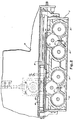
- the multi-spindle work transfer device 10, illustrated in Figure 1 which can be for a vertical boring machine, for example, is comprised of a base assembly 12 on which is mounted, through conventional means, a shuttle assembly 11 with multiple spindles 14. When positioned at cutting tool holders 15, the spindles 14 are said to be at the work zone 13. When the spindles 14 are outside the work zone 13,-they are in a load/unload position.
- the shuttle assembly 11 is comprised of two stations each-made up of two spindles 14. The shuttle 11 is caused to traverse the base 12 and alternatively present each of the stations to the work zone 13 and to the load/unload position.
- the actuator rod 19 connected to the shuttle assembly 11 is moved axially by actuator 18 which is fixed to the machine tool base assembly 12.
- actuator 18 which is fixed to the machine tool base assembly 12.
- the idler gears 24 meshed to special gear rack 17, which is affixed to the base 12, drive the spindle drive gears 21.
- the section of the gear rack 17, central to the work zone 13, has a portion of the teeth removed, see Figure 3, such that idler gears 24 can rotate free of the gear rack 17 when at the work zone 13.
- the gears 24 engage power drive gear 25 which is held fixed by high speed drive gear 29 which in turn is held locked by gear shot pin 28.
- the shuttle assembly 11 has positioned either pair of spindles 14 at the work zone 13
- the shuttle shot pin 31 engages one of the pair of notches in the work shuttle assembly to prevent any motion in the shuttle through the work cycle, the gear shot pin 28 is withdrawn and power is applied to the spindles 14 through power drive gear 25.
- the drive gear 25 is caused to stop when the slug 27 mounted on the gear 24 is aligned with proximity switch 26 fixed to shuttle assembly 11 re-establishing the precise rotational orientation of the spindles 14.
Landscapes
- Engineering & Computer Science (AREA)
- Mechanical Engineering (AREA)
- Multi-Process Working Machines And Systems (AREA)
- Turning (AREA)
- Automatic Assembly (AREA)
Applications Claiming Priority (2)
| Application Number | Priority Date | Filing Date | Title |
|---|---|---|---|
| US390178 | 1982-06-21 | ||
| US06/390,178 US4442739A (en) | 1982-06-21 | 1982-06-21 | Multi-spindle work transfer device |
Publications (2)
| Publication Number | Publication Date |
|---|---|
| EP0098960A2 true EP0098960A2 (de) | 1984-01-25 |
| EP0098960A3 EP0098960A3 (de) | 1985-07-31 |
Family
ID=23541414
Family Applications (1)
| Application Number | Title | Priority Date | Filing Date |
|---|---|---|---|
| EP83105448A Withdrawn EP0098960A3 (de) | 1982-06-21 | 1983-06-01 | Mehrspindel-Transfereinrichtung einer Werkzeugmaschine |
Country Status (4)
| Country | Link |
|---|---|
| US (1) | US4442739A (de) |
| EP (1) | EP0098960A3 (de) |
| JP (1) | JPS597501A (de) |
| CA (1) | CA1200370A (de) |
Families Citing this family (12)
| Publication number | Priority date | Publication date | Assignee | Title |
|---|---|---|---|---|
| US4741232A (en) * | 1986-11-06 | 1988-05-03 | The Warner & Swasey Company | Apparatus for use in machining workpieces |
| US4821612A (en) * | 1986-11-06 | 1989-04-18 | The Warner & Swasey Company | Method for machining workpieces |
| US4974304A (en) * | 1990-02-08 | 1990-12-04 | Sew Eurodrive, Inc. | Mounting apparatus for CNC machine |
| IT1253293B (it) * | 1991-10-31 | 1995-07-14 | Minganti Spa | Tornio verticale, predisposto per provvedere in forma autonoma, semplificata ed economica, al carico ed allo scarico dei pezzi da lavorare e lavorati |
| JP3396154B2 (ja) * | 1997-10-15 | 2003-04-14 | 株式会社森精機ハイテック | 主軸移動型立形工作機械におけるワークフィーダ |
| DE10249106B4 (de) * | 2002-10-21 | 2010-12-02 | Bystronic Laser Ag | Maschine zur Laserstrahlbearbeitung von länglichen Werkstücken |
| DE102009052984B4 (de) * | 2009-11-12 | 2015-06-18 | Emag Holding Gmbh | Drehmaschine mit zwei Werkzeugpindeln |
| JP5605502B2 (ja) * | 2011-03-24 | 2014-10-15 | 村田機械株式会社 | 工作機械システム |
| EP2548691B1 (de) * | 2011-07-22 | 2016-08-31 | TRUMPF Werkzeugmaschinen GmbH + Co. KG | Entladevorrichtung für eine Bearbeitungsvorrichtung zur Bearbeitung von Rohren mit einer in Höhenrichtung beweglichen Ablagefläche ; Verfahren zur schneidenden Bearbeitung eines Rohres mit einer solchen Vorrichtung |
| US20160030302A1 (en) * | 2014-07-31 | 2016-02-04 | Chromavis S.P.A. | Method and device for the surface working of a cosmetic product |
| CN104759932A (zh) * | 2015-03-20 | 2015-07-08 | 乔秀荣 | 刨床刀具高度调节装置 |
| CN115609023B (zh) * | 2022-12-21 | 2023-03-07 | 龙口市天工机械配件有限公司 | 一种高效的制动盘加工装置 |
Family Cites Families (6)
| Publication number | Priority date | Publication date | Assignee | Title |
|---|---|---|---|---|
| US2542318A (en) * | 1946-11-29 | 1951-02-20 | Pullman Standard Car Mfg Co | Car wheel boring machine |
| DE1602892A1 (de) * | 1967-04-29 | 1970-01-08 | Monforts Fa A | Drehmaschinen-Spindelstock mit mehreren Werkstueckspannfuttern |
| US3365989A (en) * | 1967-06-16 | 1968-01-30 | Bullard Co | Multiple turret head indexing apparatus |
| CH585092A5 (en) * | 1975-03-07 | 1977-02-28 | Jaggi Perrin & Cie | Swarf removing machine tool - has thruster mechanism alternately bringing two jigs into position for machining work |
| US4159660A (en) * | 1978-02-21 | 1979-07-03 | Ex-Cell-O Corporation | Biaxial turning machine with means for bidirectional independent tool compensation |
| US4197769A (en) * | 1978-05-05 | 1980-04-15 | The Motch & Merryweather Machinery Company | Dual spindle NC chucking/turning machine |
-
1982
- 1982-06-21 US US06/390,178 patent/US4442739A/en not_active Expired - Fee Related
-
1983
- 1983-05-12 CA CA000428026A patent/CA1200370A/en not_active Expired
- 1983-06-01 EP EP83105448A patent/EP0098960A3/de not_active Withdrawn
- 1983-06-13 JP JP58104333A patent/JPS597501A/ja active Pending
Also Published As
| Publication number | Publication date |
|---|---|
| JPS597501A (ja) | 1984-01-14 |
| CA1200370A (en) | 1986-02-11 |
| US4442739A (en) | 1984-04-17 |
| EP0098960A3 (de) | 1985-07-31 |
Similar Documents
| Publication | Publication Date | Title |
|---|---|---|
| EP0240946B1 (de) | Werkzeugmaschine | |
| US4404727A (en) | Machine tool operable as both a chucking type lathe and as a machining center | |
| US5058261A (en) | Machine tool | |
| CA1197081A (en) | Workpiece storage and shuttle apparatus | |
| EP0259637B1 (de) | Werkzeugmaschine für mehrteilige spanabhebende Bearbeitung | |
| US5020201A (en) | Machine tool | |
| US4400859A (en) | Machining centers for machining tubular workpieces | |
| US4442739A (en) | Multi-spindle work transfer device | |
| EP0215426B1 (de) | Werkzeugmaschine mit Indexiervorrichtungen | |
| US3662442A (en) | Vertical turret machine tool | |
| EP0500104A2 (de) | Werkzeugmaschine zur Verbundbearbeitung | |
| US3918331A (en) | Lathes | |
| US4700453A (en) | Turning machine | |
| US4612690A (en) | Multiple spindle machine tool | |
| EP0265586A1 (de) | Vorrichtung zum Fertigstellen von Kolben oder dgl. und Verfahren dafür | |
| US3750245A (en) | Turret lathe | |
| US3263300A (en) | Automatic tool change arrangement | |
| EP0345677A2 (de) | Palettenspeicher | |
| US3688363A (en) | Indexing machine | |
| SU928998A3 (ru) | Устройство дл автоматической смены инструментов на металлорежущем станке | |
| US1671354A (en) | Inverted unitary chucking machine | |
| US4297925A (en) | Turret head for a lathe | |
| US7012212B2 (en) | EDM drill | |
| US3365989A (en) | Multiple turret head indexing apparatus | |
| US3981056A (en) | Drive mechanisms for lathe spindles |
Legal Events
| Date | Code | Title | Description |
|---|---|---|---|
| PUAI | Public reference made under article 153(3) epc to a published international application that has entered the european phase |
Free format text: ORIGINAL CODE: 0009012 |
|
| AK | Designated contracting states |
Designated state(s): DE FR GB IT |
|
| PUAL | Search report despatched |
Free format text: ORIGINAL CODE: 0009013 |
|
| RHK1 | Main classification (correction) |
Ipc: B23B 3/32 |
|
| AK | Designated contracting states |
Designated state(s): DE FR GB IT |
|
| STAA | Information on the status of an ep patent application or granted ep patent |
Free format text: STATUS: THE APPLICATION HAS BEEN WITHDRAWN |
|
| 18W | Application withdrawn |
Withdrawal date: 19860107 |
|
| RIN1 | Information on inventor provided before grant (corrected) |
Inventor name: SWANSON, SVEN V., JR. Inventor name: SWANSON, RICHARD G. |