EP0098970A2 - Commande numérique pour une machine à meuler - Google Patents
Commande numérique pour une machine à meuler Download PDFInfo
- Publication number
- EP0098970A2 EP0098970A2 EP83105594A EP83105594A EP0098970A2 EP 0098970 A2 EP0098970 A2 EP 0098970A2 EP 83105594 A EP83105594 A EP 83105594A EP 83105594 A EP83105594 A EP 83105594A EP 0098970 A2 EP0098970 A2 EP 0098970A2
- Authority
- EP
- European Patent Office
- Prior art keywords
- grinding
- workpiece
- portions
- order
- plural sets
- Prior art date
- Legal status (The legal status is an assumption and is not a legal conclusion. Google has not performed a legal analysis and makes no representation as to the accuracy of the status listed.)
- Granted
Links
Images


Classifications
-
- B—PERFORMING OPERATIONS; TRANSPORTING
- B24—GRINDING; POLISHING
- B24B—MACHINES, DEVICES, OR PROCESSES FOR GRINDING OR POLISHING; DRESSING OR CONDITIONING OF ABRADING SURFACES; FEEDING OF GRINDING, POLISHING, OR LAPPING AGENTS
- B24B5/00—Machines or devices designed for grinding surfaces of revolution on work, including those which also grind adjacent plane surfaces; Accessories therefor
- B24B5/36—Single-purpose machines or devices
- B24B5/42—Single-purpose machines or devices for grinding crankshafts or crankpins
-
- B—PERFORMING OPERATIONS; TRANSPORTING
- B24—GRINDING; POLISHING
- B24B—MACHINES, DEVICES, OR PROCESSES FOR GRINDING OR POLISHING; DRESSING OR CONDITIONING OF ABRADING SURFACES; FEEDING OF GRINDING, POLISHING, OR LAPPING AGENTS
- B24B49/00—Measuring or gauging equipment for controlling the feed movement of the grinding tool or work; Arrangements of indicating or measuring equipment, e.g. for indicating the start of the grinding operation
-
- B—PERFORMING OPERATIONS; TRANSPORTING
- B24—GRINDING; POLISHING
- B24B—MACHINES, DEVICES, OR PROCESSES FOR GRINDING OR POLISHING; DRESSING OR CONDITIONING OF ABRADING SURFACES; FEEDING OF GRINDING, POLISHING, OR LAPPING AGENTS
- B24B51/00—Arrangements for automatic control of a series of individual steps in grinding a workpiece
-
- G—PHYSICS
- G05—CONTROLLING; REGULATING
- G05B—CONTROL OR REGULATING SYSTEMS IN GENERAL; FUNCTIONAL ELEMENTS OF SUCH SYSTEMS; MONITORING OR TESTING ARRANGEMENTS FOR SUCH SYSTEMS OR ELEMENTS
- G05B19/00—Program-control systems
- G05B19/02—Program-control systems electric
- G05B19/18—Numerical control [NC], i.e. automatically operating machines, in particular machine tools, e.g. in a manufacturing environment, so as to execute positioning, movement or co-ordinated operations by means of program data in numerical form
- G05B19/416—Numerical control [NC], i.e. automatically operating machines, in particular machine tools, e.g. in a manufacturing environment, so as to execute positioning, movement or co-ordinated operations by means of program data in numerical form characterised by control of velocity, acceleration or deceleration
- G05B19/4166—Controlling feed or in-feed
-
- G—PHYSICS
- G05—CONTROLLING; REGULATING
- G05B—CONTROL OR REGULATING SYSTEMS IN GENERAL; FUNCTIONAL ELEMENTS OF SUCH SYSTEMS; MONITORING OR TESTING ARRANGEMENTS FOR SUCH SYSTEMS OR ELEMENTS
- G05B2219/00—Program-control systems
- G05B2219/30—Nc systems
- G05B2219/36—Nc in input of data, input key till input tape
- G05B2219/36357—Tool line up, select right order of tool, optimal tool order loading, tool file
-
- G—PHYSICS
- G05—CONTROLLING; REGULATING
- G05B—CONTROL OR REGULATING SYSTEMS IN GENERAL; FUNCTIONAL ELEMENTS OF SUCH SYSTEMS; MONITORING OR TESTING ARRANGEMENTS FOR SUCH SYSTEMS OR ELEMENTS
- G05B2219/00—Program-control systems
- G05B2219/30—Nc systems
- G05B2219/45—Nc applications
- G05B2219/45159—Dressing, sharpening, trueing tool
-
- G—PHYSICS
- G05—CONTROLLING; REGULATING
- G05B—CONTROL OR REGULATING SYSTEMS IN GENERAL; FUNCTIONAL ELEMENTS OF SUCH SYSTEMS; MONITORING OR TESTING ARRANGEMENTS FOR SUCH SYSTEMS OR ELEMENTS
- G05B2219/00—Program-control systems
- G05B2219/30—Nc systems
- G05B2219/45—Nc applications
- G05B2219/45161—Grinding machine
-
- G—PHYSICS
- G05—CONTROLLING; REGULATING
- G05B—CONTROL OR REGULATING SYSTEMS IN GENERAL; FUNCTIONAL ELEMENTS OF SUCH SYSTEMS; MONITORING OR TESTING ARRANGEMENTS FOR SUCH SYSTEMS OR ELEMENTS
- G05B2219/00—Program-control systems
- G05B2219/30—Nc systems
- G05B2219/49—Nc machine tool, till multiple
- G05B2219/49375—Minimalizing machine time, number of tool change
-
- Y—GENERAL TAGGING OF NEW TECHNOLOGICAL DEVELOPMENTS; GENERAL TAGGING OF CROSS-SECTIONAL TECHNOLOGIES SPANNING OVER SEVERAL SECTIONS OF THE IPC; TECHNICAL SUBJECTS COVERED BY FORMER USPC CROSS-REFERENCE ART COLLECTIONS [XRACs] AND DIGESTS
- Y02—TECHNOLOGIES OR APPLICATIONS FOR MITIGATION OR ADAPTATION AGAINST CLIMATE CHANGE
- Y02P—CLIMATE CHANGE MITIGATION TECHNOLOGIES IN THE PRODUCTION OR PROCESSING OF GOODS
- Y02P90/00—Enabling technologies with a potential contribution to greenhouse gas [GHG] emissions mitigation
- Y02P90/02—Total factory control, e.g. smart factories, flexible manufacturing systems [FMS] or integrated manufacturing systems [IMS]
Definitions
- the present invention relates a numerical controller for controlling a grinding machine in accordance with a numerical control program to successively grind a plurality of cylindrical portions formed on a rotating workpiece.
- a grinding wheel In a numerically controlled grinding machine of the type mentioned above, a grinding wheel must be dressed to refresh its damaged or roughened grinding surface each time of grinding a plurality of portions on a workpiece. The time when such dressing becomes due varies depending largely upon the order in which the workpiece portions are ground. Frequent wheel dressings may therefore be required in the course of successive grindings of the workpiece portions unless the same are ground in an appropriate order which is determined by a particular rule of practice.
- the workpiece portions must be ground in order from one needing a higher finish accuracy to another needing a lower finish accuracy.
- one of the workpiece portions with the highest required accuracy is ground under a direct sizing control by a sizing device prior to grinidng the remaining workpiece portions under an indirect sizing control.
- any traverse grinding operation has to have preference to any plunge grinding operation wherein a workpiece portion with a wider axial width than that of a grinding wheel is ground, because unlike the traverse grinding operation, the plunge grinding operation creates a stepped local wear on the grinding surface of the grinding wheel.
- any numerically controlled grinding machine known heretofore is not given the function to automatically decide such a grinding order and thus, imposes on an operator various data preparation procedures: deciding a grinding order taking into consideration the kinds of grindings on respective portions of a workpiece, the axial widths of the workpiece portions and so forth, and inputting data indicative of the decided grinding order. Accordingly, known numerically controlled grinding machines are laborious for the operator to input machining data. In addition, if the machining
- Another object of the present invention is to provide an improved numerical controller of the character set forth above wherein the automatic decision of the gridning order is executed in such a manner as to eliminate dressing operations or decrease the number of dressing operations in the course of a series of grinding operations on the workpiece portions, thereby realizing effective use of a grinding wheel as well as reduction of a total grinding cycle time of the workpiece.
- a further object of the present invention is to provide an improved numerical controller for a grinding machine of the character set forth above wherein a data processor is utilized to automatically decide such a grinding order based upon the machining data, to automatically prepare a numerical control program based upon the decided grinding order and the machining - data and to control the grinding machine in accordance the numerical control program.
- a numerical controller for a grinding machine which comprises a data input device, a memory device, a grinding order decision circuit device and a feed control circuit device.
- the data input device enables an operator to input various grinding modes in which a plurality of portions on a workpiece are to be ground and plural sets of machining
- the grinding order decision circuit device decides a grinding order in which the workpiece portions are successively ground, based upon the grinding mode data and the machining data being stored in the memory device.
- the decision of such a grinding order is made in accordance with a predetermined rule.
- this rule is provided for decreasing the number of dressing operations effected on a grinding wheel of the grinding machine.
- the numerical control circuit device operates based upon the decided grinding order data and the machining data and controls first and second feed devices for effecting relative movement between a grinding wheel support and a workpiece support of the grinding machine so as to successively grind the workpiece portions in the decided grinding order and based upon the plural sets of machining data.
- the numerical control circuit device includes an automatic programming circuit device and a feed control device.
- the automatic programming circuit device automatically prepares a numerical control program which enables the workpiece portions to be successively ground to respective dimensions designated by the plural sets of machining data in the decided grinding order.
- the feed control circuit device controls the first and second feed device in accordance with the numerical control program.
- the order in which a plurality of workpiece portions are successively ground is automatically decided, which results in successfully reducing the kinds and number of machining data which have to be input by the operator by means of the data input device.
- effective use of the grinding wheel and reduction of a total cycle time which is taken to successively grind the workpiece portions can be accomplished beacause the grinding order is decided in accordance with a particular rule which is provided for eliminating dressing operations or decreasing the number of dressing operations in the course of a series of grinding operations on the workpiece portions.
- FIGURE 1 a grinding machine with a numerical controller according to the present invention is shown having a bed 10, which mounts on an upper-front portion thereof a work table 11 slidable in a Z-axis direction.
- the work table 11 is movable by a servomotor 12, fixedly mounted on a lateral surface of the bed 10, in the Z-axis direction.
- the work table 11 mounts thereon a work head 15 and a foot stock 17, which respectively carries a work spindle 14 rotatable by a motor 13 and a foot stock center 16.
- a work spindle center 18 and a drive pin 19 is fixedly provided on the work spindle 14.
- a step-shaped cylindrical workpiece W which as shown in FIGURE 2, has at respective axial positions thereon a plurality of portions P1-P4 to be machined, is supported between the work spindle center 18 and the foot stock center 16 and is in engagement with the drive pin 19.
- a wheel head 22 Mounted upon an upper-rear portion of the bed 10 is a wheel head 22, which is slidable in an X-axis direction perpendicular to the axis of the workpiece W.
- the wheel head 22 carries a grinding wheel 21 rotated by a wheel drive motor 20 and is movable by a servomotor 23 fixed on the rear portion of the bed 10.
- the servomotors 12 and 23 are respectively connected to drive circuits 25 and 26 to which feed pulses are distributed from a pulse generating circuit 24.
- feed pulses are supplied to the drive circuits 25 and 26, each of the wheel head 22 and the work table 11 is displaced an amount corresponding to the number of the supplied feed pulses, whereby relative position between the wheel head 22 and the work table 11 is changed to machine the workpiece W.
- the bed 10 further mounts a sizing device 28 thereon at a position facing the grinding wheel 21 through the workpice W.
- the sizing device 28 is designed to measure the diameter of each workpiece cylindrical portion being under process and to emit a number of sizing signals respectively when the daimeter of the workpiece cylindrical portion reaches predetermined values.
- the sizing device 28 is movable by a hydraulic cylinder, not shwon, to and from a sizing position indicated in FIGURE 1.
- the wheel head 22 mounts on a rear portion thereof a dressing apparatus 27 for dressing the grinding wheel 21.
- a reference numeral 31 denotes a data processor constituting a computerized numerical controller 30 along with the above-noted pulse generating circuit 24.
- the data processor 31 is connected to a memory device 32, a manual data input device (MDI) 33 and a manipulation board 35.
- the sizing device 28 is also connected to the data processor 31 through an interface, not shown, for applying the sizing signals thereto.
- the data input device 33 enables an operator to input machining data, including a grinding mode, a grinding width and a finish diameter, with respect to each of the cylindrical portions P1-P4 which are formed on the workpiece W respectively at different axial positions.
- the machining data input by the data input device 33 is stored in a machining data buffer area MDBA of the memory device 32 under the control of the data processor 31.
- each grinding position data indicates an axial distance between a reference surface (e.g., Zl in FIGURE 2) and the left end of each cylindrical portion to be ground, along the axis of the workpiece W.
- Grinding mode data PID, PD and TID respectively represent an indirect sizing plunge grinding mode, a direct sizing plunge grinding mode and an indirect sizing traverse grinding mode.
- the finish accuracy for each cylindrical portion is represented by a value of finish grade, wherein a smaller value means a higher finish accuracy.
- step 40 of a routine shown in FIGURE 4(a) to decide the order in which the plurality of workpiece portions P1-P4 are to be machined.
- the grinding order is decided based upon the machining data for the cylindrical portions Pl-P4 shown in TABLE 1 and is registered in a grinding order write-in table MOWT provided in the memory device 32.
- step 41 is next reached, wherein there is prepared a numerical control program (hereafter referred to as "NC program" for use in machining the plurality of cylindrical portions Pl-P4 in the decided grinding order.
- NC program a numerical control program
- NC data including table indexing positions, rapid feed amounts, rough grinding infeed amounts and fine grinding infeed amounts are calculated based upon the above-noted grinding position data, initial diameter data, finish diameter data and the like and are stored in an NC data area NCDA of the memory device 33.
- the preparation processings for the NC program are executed for respective cylindrical portions Pl-P4 in the same order as the grinding order determined in step 40.
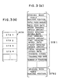
- Respective NC program segments prepared for the cylindrical portions Pl-P4 are successively written in a plurality of data tables STB1-STB4 which as shown in FIGURE 3(a), are provided in the NC data area NCDA of the memory device 32.
- FIGURE 3(b) typically shows the detail of one of the NC program segments which is prepared for the cylndircal portion P2 and which is stored in the data table STB1.
- Each of these data tables STB1-STB4 stores data indicative of a grinding mode at its first memory address and also stores table indexing position data. rapid feed amount data, rapid feed rate data and so forth respectively at other memory addresses contiguous to the first memory address.
- a table traverse feed stroke is calculated based upon input data indicative of a grinding width and along with the number of times of traverse feed movements and the like which are also automatically calculated, is stored in appropriate memory addresses of each data table.
- feed rate data such as wheel head infeed rate, table traverse feed rate and the like are chosen from those data which have been stored in a parameter storage area, not shown, in advance and are respectively stored in other appropriate memory addresses of each data table.
- the preparation of the NC program is completed in the foregoing manner.
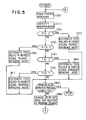
- the data processor 31 executes an NC execution routine shown in FIGURE 5, whereby the cylindrical portions Pl-P4 are ground in the decided grinding order and whereby each of the cylindrical portions Pl-P4 is ground in a grinding mode designated thereto and in accordance with an NC program segment including various control data prepared therefor.
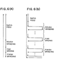
- FIGURES 6(a) and 6(b) show grinding cycle charts indicating relative feed movements between the work table 11 and the wheel head 22 in a plunge grinding mode and a traverse grinding mode, respectively.
- each of the plunge grinding mode and the traverse grinding mode needs the direct control by the sizing device 28, the pulse distribution in each of a rough grinding step, a fine grinding step and a final grinding step is discontinued in response to the corresponding one of the sizing signals from the sizing device 28.
- the pulse distribution in each grinding step is discontinued when the feed amount in each grinding step coincides with an amount calculated and designated. The repetition of the above-described operations results in grinding the plurality of cylindrical portions Pl-P4 in the decided grinding order.
- the data processor 31 first initializes the grinding order write-in table MOWT of the memory device 32 in step 50 of FIGURE 4(b) and then, sets "1" in an order counter, not shwon, in step 51.
- Step 52 is next reached, wherein the data processor 31 executes processings for selecting one of the cylindrical portions P1-P4 which is to be first machined.
- such selection is made in such a manner that one or more portions to be machined under the direct control of the sizing device 28 are preferentially machined, successive to which one or more other portions to be machined in a traverse grinding mode are next machined, and that the remaining portions to be machined in a plunge grinding mode are finally machined in an order of one having the widest width to another having the narrowest width.
- step 60 there is first selected in step 60 a portion which should be machined under the direct control of the sizing device 28 to have a high finish accuracy and to thereby become a reference for the machinings of other portions. If two or more portions of the workpiece W require the direct control by the sizing device 28, the routine of the data processor 31 is advanced from step 60 to the right in FIGURE 4(c), whereby there is first selected a portion needing the highest machining accuracy, from those which are to be machined under the direct control of the sizing device 28. If this does not yet permit a particular one to be selected out of those portions, the criterion for selection is in turn changed for one which is to be machined in a traverse grinding mode and further, for one which has the widest width of all. Furthermore, if the above-noted criterions still do not permit a particular one to be selected out of those portions, a portion nearest to one which has been specified in a latest or preceding selection operation is finally selected out.
- the routine of the data processor 31 is moved from one of steps 60 and 60a-60d to step 53 of FIGURE 4(b).
- the counted value "1" of the order counter OC is written in a memory address which is of a plurality of memory addresses reserved in the grinding order write-in table MOWT and which is allocated to the selected workpiece portion, namely, to the portion P2 in this particular instance, as shown in the following TABLE 2.
- step 55 is next executed to increment the content of the grinding order in step 56 counter OC and it is ascertained whether or not, the machining order has been determined with respect to all of the workpiece portions PI-P4 to be machined. If like in this described case, it has not yet been determined with respect to all of the workpiece portions P1-P4, return is then made from step 56 to step 52, whereby the foregoing processings are repeated for deciding the machining order with respect to the remaining workpiece portions to be machined.
- Step 53 of FIGURE 4(b) is next reached, wherein the presently counted value "2" of the grinding order counter OC is written in a memory address of the grinding order write-in table MOWT allocated to the workpiece portion P3, and the counted value of the order counter OC is then incremented in step 55.
- the data processor 31 returns its routine from step 56 to step 52 to execute the foregoing processings again.
- step 61 to 62 the processing by the data processor 31 in the grinding order decision routine shown in FIGURE 4(c) is directed from step 61 to 62, thereby selecting the workpiece portions P1 with a wider width so that in step 53, the counted value "3" of the order counter OC is written in a memory address of the grinding order write-in table MOWT allocated to the selected portion P1.
- steps 55 and 56 are followed to return to step 52, wherein the foregoing processings are executed again with the result of writing the counted value "4" of the order counter OC in another address of the grinding order write-in table MOWT allocated to the workpiece portion P4, thereby completing the processings for decision of grinding order.
- the grinding order deciding routine shown in FIGURE 4(c) is arranged such that if the workpiece W has a number of portions each needing a traverse grinding, a portion with a higher required accuracy has preference to another portion nearer to one which has alreadly been specified in a preceding selection operation.
- the routine is further arranged such that if the workpiece W has a number of workpiece portions each needing a plunge grinding operation under the indirect sizing control and having the same width as each other, selection is carried out for one of the workpiece portions nearest to another which has already been specified in a preceding selection operation.
- the NC program for the workpiece W is automatically prepared based upon the machining data and the decided grinding order and is stored in the NC data area NCDA, as described earlier.
- the NC program segments for the respective workpiece portions Pl-P4 are successively read out in such an order as they were stored, and the workpiece portions Pl-P4 are successively ground in accordance with the NC program segments.
- the workpiece portions P1-P4 are consecutively machined in the grinding order which has been decided pursuant to the abov-described procedual process. This advantageously makes it possible to precisely grind the plurality of portions P1-P4 on the workpiece W without performing a dressing operation in the course of machining all portions P1-P4 of the workpiece W.
Landscapes
- Engineering & Computer Science (AREA)
- Mechanical Engineering (AREA)
- Human Computer Interaction (AREA)
- Manufacturing & Machinery (AREA)
- Physics & Mathematics (AREA)
- General Physics & Mathematics (AREA)
- Automation & Control Theory (AREA)
- Constituent Portions Of Griding Lathes, Driving, Sensing And Control (AREA)
- Numerical Control (AREA)
Applications Claiming Priority (2)
| Application Number | Priority Date | Filing Date | Title |
|---|---|---|---|
| JP57107772A JPS591164A (ja) | 1982-06-23 | 1982-06-23 | 数値制御研削盤 |
| JP107772/82 | 1982-06-23 |
Publications (4)
| Publication Number | Publication Date |
|---|---|
| EP0098970A2 true EP0098970A2 (fr) | 1984-01-25 |
| EP0098970A3 EP0098970A3 (en) | 1985-07-03 |
| EP0098970B1 EP0098970B1 (fr) | 1988-12-14 |
| EP0098970B2 EP0098970B2 (fr) | 1993-03-17 |
Family
ID=14467617
Family Applications (1)
| Application Number | Title | Priority Date | Filing Date |
|---|---|---|---|
| EP83105594A Expired - Lifetime EP0098970B2 (fr) | 1982-06-23 | 1983-06-07 | Commande numérique pour une machine à meuler |
Country Status (4)
| Country | Link |
|---|---|
| US (1) | US4498259A (fr) |
| EP (1) | EP0098970B2 (fr) |
| JP (1) | JPS591164A (fr) |
| DE (1) | DE3378699D1 (fr) |
Cited By (4)
| Publication number | Priority date | Publication date | Assignee | Title |
|---|---|---|---|---|
| FR2579503A1 (fr) * | 1985-03-29 | 1986-10-03 | Toyoda Machine Works Ltd | Machine a rectifier a commande numerique |
| GB2239327A (en) * | 1989-11-24 | 1991-06-26 | Okuma Machinery Works Ltd | Automatic machining |
| EP0480269A3 (en) * | 1990-09-28 | 1993-03-03 | Toyoda Koki Kabushiki Kaisha | Numerically controlled grinding machine |
| WO2000013848A1 (fr) * | 1998-09-03 | 2000-03-16 | Anca Pty. Ltd. | Taille d'outils coupants a aretes ondulees |
Families Citing this family (21)
| Publication number | Priority date | Publication date | Assignee | Title |
|---|---|---|---|---|
| JPS59146308A (ja) * | 1983-02-10 | 1984-08-22 | Mitsubishi Electric Corp | 数値制御装置 |
| JPS619705A (ja) * | 1984-06-25 | 1986-01-17 | Toyoda Mach Works Ltd | 数値制御工作機械 |
| JPS6257852A (ja) * | 1985-09-04 | 1987-03-13 | Toyoda Mach Works Ltd | 自動プログラミング装置 |
| IT1191688B (it) * | 1986-03-20 | 1988-03-23 | Giustina International Spa | Macchina rettificatrice per cilindri con organi di rilievo e controllo dimensionale e superficiale |
| US4748554A (en) * | 1986-08-14 | 1988-05-31 | Gte Valeron Corporation | Machine monitoring system using motion detection for synchronization |
| US5204820A (en) * | 1987-03-11 | 1993-04-20 | Eastman Kodak Company | Method of producing an optically effective arrangement in particular for application with a vehicular headlight |
| JPS6420913A (en) * | 1987-07-14 | 1989-01-24 | Tosa Kiko Kk | End mill |
| US4887221A (en) * | 1987-09-25 | 1989-12-12 | Sunnen Products Company | Computer controlled honing machine using look up table data for automatic programming |
| JPH0652484B2 (ja) * | 1988-02-15 | 1994-07-06 | 豊田工機株式会社 | 非真円形工作物加工用数値制御装置 |
| JPH0683945B2 (ja) * | 1988-07-26 | 1994-10-26 | 豊田工機株式会社 | 非真円形工作物加工用数値制御装置 |
| US5247791A (en) * | 1989-10-25 | 1993-09-28 | Pyong S. Pak | Power generation plant and power generation method without emission of carbon dioxide |
| US5173863A (en) * | 1990-04-25 | 1992-12-22 | Pace Technologies | Programmable surface grinder having a teach mode with independent table speed adjustment |
| JP3084287B2 (ja) * | 1990-11-29 | 2000-09-04 | 豊田工機株式会社 | 加工データ作成装置 |
| US5189846A (en) * | 1992-02-24 | 1993-03-02 | Caterpillar Inc. | Chuck indexing arrangement and method |
| GB9615511D0 (en) * | 1996-07-24 | 1996-09-04 | Western Atlas Uk Ltd | Improvements relating to grinding methods and apparatus |
| JPH10138182A (ja) * | 1996-11-08 | 1998-05-26 | Toyoda Mach Works Ltd | ロボットの教示装置 |
| JP2898279B1 (ja) * | 1998-05-26 | 1999-05-31 | 株式会社ゼクセル | 研削加工装置 |
| JP3649037B2 (ja) * | 1999-04-14 | 2005-05-18 | 豊田工機株式会社 | 複合研削盤 |
| JP5339518B2 (ja) * | 2009-02-17 | 2013-11-13 | ダイハツ工業株式会社 | クランクシャフトの研削方法 |
| US9180559B2 (en) * | 2012-08-16 | 2015-11-10 | Nsk Americas, Inc. | Apparatus and method for measuring bearing dimension |
| CN110834242B (zh) * | 2019-11-27 | 2025-04-29 | 科德数控股份有限公司 | 一种龙门磨床 |
Family Cites Families (9)
| Publication number | Priority date | Publication date | Assignee | Title |
|---|---|---|---|---|
| US3746956A (en) * | 1971-04-02 | 1973-07-17 | Toyoda Machine Works Ltd | Tape-reading control system for repeat-processing cycles of traverse cutting |
| JPS5244476B2 (fr) * | 1972-01-13 | 1977-11-08 | ||
| US3934185A (en) * | 1973-01-10 | 1976-01-20 | Landis Tool Company | Machine tool control system |
| US3824743A (en) * | 1973-05-22 | 1974-07-23 | Landis Tool Co | Machine tool control system |
| IT1013609B (it) * | 1974-05-09 | 1977-03-30 | Finike Italiana Marpuss Soc In | Metodo e relativa apparecchiatura per il comando e la regolazione dei cicli di lavorazione di una macchina utensile |
| JPS542953B2 (fr) * | 1974-05-17 | 1979-02-15 | ||
| US4061952A (en) * | 1975-04-14 | 1977-12-06 | Cranfield Institute Of Technology | Computer-controlled machine tool |
| US4292766A (en) * | 1978-03-16 | 1981-10-06 | The Warner & Swasey Company | Method and apparatus for grinding a workpiece |
| US4328448A (en) * | 1980-09-02 | 1982-05-04 | Cincinnati Milacron Inc. | Method for programmably controlling the sequence of execution of data blocks in a program |
-
1982
- 1982-06-23 JP JP57107772A patent/JPS591164A/ja active Granted
-
1983
- 1983-06-07 EP EP83105594A patent/EP0098970B2/fr not_active Expired - Lifetime
- 1983-06-07 DE DE8383105594T patent/DE3378699D1/de not_active Expired
- 1983-06-13 US US06/503,589 patent/US4498259A/en not_active Expired - Lifetime
Cited By (7)
| Publication number | Priority date | Publication date | Assignee | Title |
|---|---|---|---|---|
| FR2579503A1 (fr) * | 1985-03-29 | 1986-10-03 | Toyoda Machine Works Ltd | Machine a rectifier a commande numerique |
| GB2239327A (en) * | 1989-11-24 | 1991-06-26 | Okuma Machinery Works Ltd | Automatic machining |
| GB2239327B (en) * | 1989-11-24 | 1994-05-11 | Okuma Machinery Works Ltd | Method for determining inner diameter machining method in numerical control information generating function |
| EP0480269A3 (en) * | 1990-09-28 | 1993-03-03 | Toyoda Koki Kabushiki Kaisha | Numerically controlled grinding machine |
| US5271187A (en) * | 1990-09-28 | 1993-12-21 | Toyoda Koki Kabushiki Kaisha | Numerically controlled grinding machine |
| WO2000013848A1 (fr) * | 1998-09-03 | 2000-03-16 | Anca Pty. Ltd. | Taille d'outils coupants a aretes ondulees |
| US6632123B1 (en) | 1998-09-03 | 2003-10-14 | Anca Pty Ltd | Grinding of cutting tools with wavy cutting edges |
Also Published As
| Publication number | Publication date |
|---|---|
| US4498259A (en) | 1985-02-12 |
| EP0098970A3 (en) | 1985-07-03 |
| EP0098970B1 (fr) | 1988-12-14 |
| JPS591164A (ja) | 1984-01-06 |
| DE3378699D1 (en) | 1989-01-19 |
| JPH052458B2 (fr) | 1993-01-12 |
| EP0098970B2 (fr) | 1993-03-17 |
Similar Documents
| Publication | Publication Date | Title |
|---|---|---|
| EP0098970B1 (fr) | Commande numérique pour une machine à meuler | |
| US4570387A (en) | Centerless grinding machine | |
| EP0093955B1 (fr) | Appareil de commande pour une machine à meuler | |
| US5127140A (en) | Numerically-controlled lathe, numerically-controlled device therefor and processing procedure thereby | |
| DE68912221T2 (de) | Numerisch gesteuerte Schleifmaschine. | |
| DE3886138T2 (de) | Numerisch gesteuerte Werkzeugmaschine. | |
| EP0164686B1 (fr) | Commande numérique interactive pour une machine outil | |
| EP0352725B1 (fr) | Commande numérique pour l'usinage de pièces non circulaires | |
| EP0104542B1 (fr) | Méthode d'usinage à commande numérique | |
| US5766059A (en) | Method of grinding a workpiece | |
| JPH077296B2 (ja) | 非真円形工作物加工用数値制御装置 | |
| EP1380385B1 (fr) | Procédé pour meuler simultanément plusieurs parties d'une pièce | |
| JP4947534B2 (ja) | 工作機械及び工作機械を操作する方法 | |
| US4740902A (en) | Numerical control apparatus having memory storage for machine patterns, plural individually selectable remachining patterns, and control parameters | |
| US4736326A (en) | Numerical control apparatus for grinding machine capable of grinding taper and non-taper portions of workpiece | |
| JPS5840257A (ja) | 円弧状隅部の研削方法 | |
| JPS6090652A (ja) | 数値制御工作機械 | |
| JPH08112701A (ja) | Nc旋盤による加工方法及びバックアップ加工可能なnc旋盤 | |
| JPS6147652B2 (fr) | ||
| JP2000107982A (ja) | 工作方法及び工作装置 | |
| JP3009216B2 (ja) | 数値制御研削盤の砥石自動修正装置 | |
| JP2764012B2 (ja) | 研削装置 | |
| JP2839685B2 (ja) | 研削データの自動決定方法 | |
| JPH01205954A (ja) | 工作機械の工具径路自動決定装置 | |
| JPH0523911B2 (fr) |
Legal Events
| Date | Code | Title | Description |
|---|---|---|---|
| PUAI | Public reference made under article 153(3) epc to a published international application that has entered the european phase |
Free format text: ORIGINAL CODE: 0009012 |
|
| 17P | Request for examination filed |
Effective date: 19830607 |
|
| AK | Designated contracting states |
Designated state(s): DE FR GB SE |
|
| PUAL | Search report despatched |
Free format text: ORIGINAL CODE: 0009013 |
|
| AK | Designated contracting states |
Designated state(s): DE FR GB SE |
|
| 17Q | First examination report despatched |
Effective date: 19870728 |
|
| GRAA | (expected) grant |
Free format text: ORIGINAL CODE: 0009210 |
|
| AK | Designated contracting states |
Kind code of ref document: B1 Designated state(s): DE FR GB SE |
|
| REF | Corresponds to: |
Ref document number: 3378699 Country of ref document: DE Date of ref document: 19890119 |
|
| ET | Fr: translation filed | ||
| PLBI | Opposition filed |
Free format text: ORIGINAL CODE: 0009260 |
|
| 26 | Opposition filed |
Opponent name: FRITZ STUDER AG Effective date: 19890902 |
|
| PUAH | Patent maintained in amended form |
Free format text: ORIGINAL CODE: 0009272 |
|
| STAA | Information on the status of an ep patent application or granted ep patent |
Free format text: STATUS: PATENT MAINTAINED AS AMENDED |
|
| 27A | Patent maintained in amended form |
Effective date: 19930317 |
|
| AK | Designated contracting states |
Kind code of ref document: B2 Designated state(s): DE FR GB SE |
|
| ET3 | Fr: translation filed ** decision concerning opposition | ||
| EAL | Se: european patent in force in sweden |
Ref document number: 83105594.2 |
|
| PGFP | Annual fee paid to national office [announced via postgrant information from national office to epo] |
Ref country code: SE Payment date: 19970618 Year of fee payment: 15 |
|
| PG25 | Lapsed in a contracting state [announced via postgrant information from national office to epo] |
Ref country code: SE Free format text: LAPSE BECAUSE OF NON-PAYMENT OF DUE FEES Effective date: 19980608 |
|
| EUG | Se: european patent has lapsed |
Ref document number: 83105594.2 |
|
| REG | Reference to a national code |
Ref country code: GB Ref legal event code: IF02 |
|
| PGFP | Annual fee paid to national office [announced via postgrant information from national office to epo] |
Ref country code: GB Payment date: 20020605 Year of fee payment: 20 |
|
| PGFP | Annual fee paid to national office [announced via postgrant information from national office to epo] |
Ref country code: FR Payment date: 20020610 Year of fee payment: 20 |
|
| PGFP | Annual fee paid to national office [announced via postgrant information from national office to epo] |
Ref country code: DE Payment date: 20020612 Year of fee payment: 20 |
|
| PG25 | Lapsed in a contracting state [announced via postgrant information from national office to epo] |
Ref country code: GB Free format text: LAPSE BECAUSE OF EXPIRATION OF PROTECTION Effective date: 20030606 |
|
| REG | Reference to a national code |
Ref country code: GB Ref legal event code: PE20 |