EP0099043A2 - Système pour commander la consommation d'énergie électrique, de préférence pour l'usage domestique - Google Patents
Système pour commander la consommation d'énergie électrique, de préférence pour l'usage domestique Download PDFInfo
- Publication number
- EP0099043A2 EP0099043A2 EP83106516A EP83106516A EP0099043A2 EP 0099043 A2 EP0099043 A2 EP 0099043A2 EP 83106516 A EP83106516 A EP 83106516A EP 83106516 A EP83106516 A EP 83106516A EP 0099043 A2 EP0099043 A2 EP 0099043A2
- Authority
- EP
- European Patent Office
- Prior art keywords
- load computer
- devices
- switching
- computer
- load
- Prior art date
- Legal status (The legal status is an assumption and is not a legal conclusion. Google has not performed a legal analysis and makes no representation as to the accuracy of the status listed.)
- Granted
Links
Images
Classifications
-
- G—PHYSICS
- G01—MEASURING; TESTING
- G01R—MEASURING ELECTRIC VARIABLES; MEASURING MAGNETIC VARIABLES
- G01R21/00—Arrangements for measuring electric power or power factor
-
- H—ELECTRICITY
- H02—GENERATION; CONVERSION OR DISTRIBUTION OF ELECTRIC POWER
- H02J—ELECTRIC POWER NETWORKS; CIRCUIT ARRANGEMENTS OR SYSTEMS FOR SUPPLYING OR DISTRIBUTING ELECTRIC POWER; SYSTEMS FOR STORING ELECTRIC ENERGY
- H02J3/00—Circuit arrangements for AC mains or AC distribution networks
- H02J3/12—Arrangements for adjusting voltage in AC networks by changing a characteristic of the network load
- H02J3/14—Arrangements for adjusting voltage in AC networks by changing a characteristic of the network load by switching loads on to, or off from, the networks, e.g. progressively balanced loading
-
- H—ELECTRICITY
- H02—GENERATION; CONVERSION OR DISTRIBUTION OF ELECTRIC POWER
- H02J—ELECTRIC POWER NETWORKS; CIRCUIT ARRANGEMENTS OR SYSTEMS FOR SUPPLYING OR DISTRIBUTING ELECTRIC POWER; SYSTEMS FOR STORING ELECTRIC ENERGY
- H02J2105/00—Networks for supplying or distributing electric power characterised by their spatial reach or by the load
- H02J2105/40—Networks for supplying or distributing electric power characterised by their spatial reach or by the load characterised by the loads connecting to the networks or being supplied by the networks
- H02J2105/42—Home appliances
-
- Y—GENERAL TAGGING OF NEW TECHNOLOGICAL DEVELOPMENTS; GENERAL TAGGING OF CROSS-SECTIONAL TECHNOLOGIES SPANNING OVER SEVERAL SECTIONS OF THE IPC; TECHNICAL SUBJECTS COVERED BY FORMER USPC CROSS-REFERENCE ART COLLECTIONS [XRACs] AND DIGESTS
- Y02—TECHNOLOGIES OR APPLICATIONS FOR MITIGATION OR ADAPTATION AGAINST CLIMATE CHANGE
- Y02B—CLIMATE CHANGE MITIGATION TECHNOLOGIES RELATED TO BUILDINGS, e.g. HOUSING, HOUSE APPLIANCES OR RELATED END-USER APPLICATIONS
- Y02B70/00—Technologies for an efficient end-user side electric power management and consumption
- Y02B70/30—Systems integrating technologies related to power network operation and communication or information technologies for improving the carbon footprint of the management of residential or tertiary loads, i.e. smart grids as climate change mitigation technology in the buildings sector, including also the last stages of power distribution and the control, monitoring or operating management systems at local level
-
- Y—GENERAL TAGGING OF NEW TECHNOLOGICAL DEVELOPMENTS; GENERAL TAGGING OF CROSS-SECTIONAL TECHNOLOGIES SPANNING OVER SEVERAL SECTIONS OF THE IPC; TECHNICAL SUBJECTS COVERED BY FORMER USPC CROSS-REFERENCE ART COLLECTIONS [XRACs] AND DIGESTS
- Y02—TECHNOLOGIES OR APPLICATIONS FOR MITIGATION OR ADAPTATION AGAINST CLIMATE CHANGE
- Y02B—CLIMATE CHANGE MITIGATION TECHNOLOGIES RELATED TO BUILDINGS, e.g. HOUSING, HOUSE APPLIANCES OR RELATED END-USER APPLICATIONS
- Y02B70/00—Technologies for an efficient end-user side electric power management and consumption
- Y02B70/30—Systems integrating technologies related to power network operation and communication or information technologies for improving the carbon footprint of the management of residential or tertiary loads, i.e. smart grids as climate change mitigation technology in the buildings sector, including also the last stages of power distribution and the control, monitoring or operating management systems at local level
- Y02B70/3225—Demand response systems, e.g. load shedding, peak shaving
-
- Y—GENERAL TAGGING OF NEW TECHNOLOGICAL DEVELOPMENTS; GENERAL TAGGING OF CROSS-SECTIONAL TECHNOLOGIES SPANNING OVER SEVERAL SECTIONS OF THE IPC; TECHNICAL SUBJECTS COVERED BY FORMER USPC CROSS-REFERENCE ART COLLECTIONS [XRACs] AND DIGESTS
- Y04—INFORMATION OR COMMUNICATION TECHNOLOGIES HAVING AN IMPACT ON OTHER TECHNOLOGY AREAS
- Y04S—SYSTEMS INTEGRATING TECHNOLOGIES RELATED TO POWER NETWORK OPERATION, COMMUNICATION OR INFORMATION TECHNOLOGIES FOR IMPROVING THE ELECTRICAL POWER GENERATION, TRANSMISSION, DISTRIBUTION, MANAGEMENT OR USAGE, i.e. SMART GRIDS
- Y04S20/00—Management or operation of end-user stationary applications or the last stages of power distribution; Controlling, monitoring or operating thereof
- Y04S20/20—End-user application control systems
- Y04S20/222—Demand response systems, e.g. load shedding, peak shaving
-
- Y—GENERAL TAGGING OF NEW TECHNOLOGICAL DEVELOPMENTS; GENERAL TAGGING OF CROSS-SECTIONAL TECHNOLOGIES SPANNING OVER SEVERAL SECTIONS OF THE IPC; TECHNICAL SUBJECTS COVERED BY FORMER USPC CROSS-REFERENCE ART COLLECTIONS [XRACs] AND DIGESTS
- Y04—INFORMATION OR COMMUNICATION TECHNOLOGIES HAVING AN IMPACT ON OTHER TECHNOLOGY AREAS
- Y04S—SYSTEMS INTEGRATING TECHNOLOGIES RELATED TO POWER NETWORK OPERATION, COMMUNICATION OR INFORMATION TECHNOLOGIES FOR IMPROVING THE ELECTRICAL POWER GENERATION, TRANSMISSION, DISTRIBUTION, MANAGEMENT OR USAGE, i.e. SMART GRIDS
- Y04S20/00—Management or operation of end-user stationary applications or the last stages of power distribution; Controlling, monitoring or operating thereof
- Y04S20/20—End-user application control systems
- Y04S20/242—Home appliances
Definitions
- the invention relates to a system for controlling electrical energy consumption, preferably in households, with an electricity meter, which outputs a pulse sequence with power proportional frequency to a load computer on the output side, with a measuring period transmitter and with switching elements assigned to the individual energy-consuming devices or device groups, these switching elements from the load computer can be influenced as a result of a comparison between a limit value and the actual power value for a measuring period according to a priority sequence stored in the load computer and device performance.
- Such a system is known from DE-OS 27 08 883.
- an electronic maximum monitor to which information about the measurement period and a pulse train with a power-proportional frequency are fed.
- This maximum monitor has a computer as a load computer and a non-volatile memory for maximum monitoring and the setting of at least one power limit value and the control of Devices via switching elements.
- the priorities for switching the devices off and on are programmed in the load computer.
- the load computer uses the energy already used and the instantaneous power to calculate whether devices are to be switched off or can still be switched on.
- the performance of the individual devices is stored in the memory as additional information.
- This system offers greater convenience compared to the switching off or switching on of power-intensive devices triggered centrally by the electricity supply companies via ripple control receivers, since the consumer of electrical energy can specify the priority order even for the individual devices.
- this priority ranking is additionally modified by including the performance of the individual devices in the decision-making process regarding the disconnection or connection. This can lead to the priority sequence desired by the consumer of electrical energy being overridden, taking into account the device power when switching the devices on or off, so that switching operations which do not take sufficient account of the needs of the consumer of electrical energy can still occur.
- the invention has for its object to improve a system of the type mentioned in such a way that a more user-friendly modification of the priority sequence takes place when switching devices on or on.
- the load computer additionally has a non-volatile memory in which the time constants of the individual devices or device groups are stored, that each device or each device group has a current sensor for the current flowing to the device or device group, its output signal is fed to the load computer, and that when the switching elements are actuated by the load computer, the time constants of the device or the device group and the previous current flow times are taken into account.
- the programmed priority sequence only offers a general framework for switching off and switching on the individual devices or groups of devices, but which is so variable that it is associated with the least possible impairment for the consumer of electrical energy.
- the hot water storage tank is not switched off first in all cases when the actual power value of the customer reaches the limit, while the freezer is switched off first if the limit value remains below after switching off the hot water tank, would continue to be operated. If, due to the time constant and the elapsed current flow time until the switch-off decision, it appears that the freezer has almost reached its lower limit temperature while the hot water tank is only at the beginning of a heating cycle, then the freezer is switched off, contrary to the priority sequence programmed per se, whereas the hot water tank is further heated.
- the load computer determines the connection of devices or device groups, taking into account the priority, the time constants and the previous switch-off time.
- the least possible impairment of the use of his devices or groups of devices is achieved by the shutdown or a connection that modifies the priority sequence depending on the time constant and the previous shutdown time.
- the decisive factor here is the modification of the programmed priority sequence by incorporating the previous history and the technical properties of the devices or device groups which affect the convenience of the consumer of electrical energy the self-adapting priority sequence determining the necessary disconnections and connections.
- Such a system can be used, for example, for the individual devices within an apartment or for entire groups of devices with the same time constant and comparable current flow duration, for example within a high-rise building.
- time constant is understood in the case of temperature-controlled devices, such as, for example, refrigerators, freezers, storage ovens, hot water tanks, electric ovens, night storage ovens, air conditioning systems, which determine the thermal inertia when heating or cooling the device or the physical quantity determining the medium to be thermally influenced by the device.
- temperature-controlled devices such as, for example, refrigerators, freezers, storage ovens, hot water tanks, electric ovens, night storage ovens, air conditioning systems, which determine the thermal inertia when heating or cooling the device or the physical quantity determining the medium to be thermally influenced by the device.
- non-temperature-controlled devices for example a feed pump, which is intended to provide a certain water supply in a water reservoir
- the "time constant" would have to be determined, for example, from the available water supply and the average withdrawal quantity per unit of time.
- a receiver is provided for the transmission of signals from the electricity supply company for removal, which is connected to the electricity meter and / or the load computer.
- tariff changes can be made on the electricity meter, but the utility company can also set corresponding limit values for the load computer.
- the command can be given to the load computer to carry out an emergency shutdown, ie actuation of all switching elements for the total shutdown of all devices or device groups. This means that the electricity supply company can influence the system from the outside. By specifying a very low limit value for the load computer, an excessively high load peak can thus be reduced, the load computer still providing for the customer electrical energy least annoying alternative is selected.
- a transmitter can be provided for the transmission of system data to the electricity supply company.
- system data can represent the current output, for example, so that the electricity supply company has a differentiated picture of the performance requirements of, for example, households and industrial plants.
- this system data can also provide the electricity supply company with information about the types of equipment currently operating in a household.
- An advantageous embodiment consists in that the load computer, based on a signal arriving at the receiver in the event of a network overload, in accordance with the priority sequence modified by the load computer, issues a switch-off command at least to individual switching elements, manual restart being excluded.
- the electricity supply company is given the opportunity to force a reduction in electrical energy consumption that cannot be eliminated by the customer or total shutdown of the electrical devices or device groups.
- the load computer can be designed as a programmable computer with several work programs, at least the program determining the switching off of the devices or device groups according to the priority sequence, time constant and previous current flow duration can be activated by a signal arriving at the receiver. This gives the electricity supply company the additional option of different work pro to specify programs for the load computer, which leads to a high flexibility of the system.
- a "gentle" form of influencing energy consumption is achieved in that the electricity meter is designed to be tariff-switchable.
- the tariff changeover is preferably carried out by the load computer.
- the tariff changeover can be triggered by a signal emitted by the electricity supply company via the receiver on the electricity meter. This makes the largely self-sufficient system for controlling energy consumption accessible to direct influence by the electricity supply company.
- the electricity meter and load computer are designed as an integrated unit.
- the transmitter, receiver, load computer and electricity meter can be designed as an integrated unit. This allows an extremely compact design and also enables the double use of components, for example display units, memories or the load computer, which is preferably designed as a microcomputer and can take on additional tasks for these devices.
- the electrical supply network can serve as a transmission path between the electricity supply company and the receiver. In the same way, the electrical supply network can serve as a transmission path between the transmitter and the power supply company. Compared to transmission by electromagnetic waves, this ensures that the transmitter and receiver can be reliably addressed without the use of antenna systems which increase the expenditure.
- the limit value for the load computer can be permanently programmed. In a more flexible embodiment, however, the limit value for the load computer can be predefined by the electricity supply company via the receiver to the load computer.
- devices or device groups are switched off for periods of time which are integer multiples of the measuring period specified by the measuring period transmitter. This means that devices or device groups can be switched on again without having to set their own switch-on criteria, although this allows the system to be even more adaptable. If the limit value is still exceeded after re-activation, the unit is switched off again for a specified time, so that longer switch-offs can always be built up as integer multiples of the measuring period without the need for complicated switch-on criteria.
- the load computer is set up to predict the expected maximum power.
- a bottleneck can thus be identified at an early stage by comparison with the limit value to be observed for the electrical power, so that the early shutdown of individual devices or device groups with a comparatively low priority sequence can prevent the subsequent shutdown of devices or device groups with a high priority sequence.
- each switching element has bistable behavior and can be converted into each of the stable states by signals at at least one control input.
- the switch-off and switch-on controlled by the load computer can thus be carried out remotely.
- the switching element can also be operated manually. The switching element can thus directly replace the device switch.
- the consumer of electrical energy thus has the possibility of manually correcting unwanted switching operations of the load computer.
- the switching element can have a locking device against manual restart, which can be activated by a signal at the control input.
- the sensor for the current flowing to the device or to the device group can be arranged in the switching element. Since any device or device group is connected to the supplying electrical network via a switching element, the sensor can be accommodated without any intervention on the device side.
- the switching element can have an overcurrent release, so that in the event of an overload or a short circuit, the device or the device group can be switched off quickly is.
- An advantageous embodiment consists in that the voltage drop at the current-carrying element of the overcurrent release used as a sensor is available at an output of the switching element for the feedback to the load computer. It is therefore not necessary to provide a separate sensor for the current flowing to the device or to the device group, so that construction volume and costs are saved.
- the overcurrent release can be designed as a thermal release, for example as a bimetal contact, or as a magnetic release.
- the switching commands of the load computer and the output signal of the sensor for the current flow are to be transmitted.
- An alternative embodiment is that for the signal transmission between the load computer and switching element, both the load computer and the switching element, a transmitter-receiver module is assigned, and that the signal transmission in the form of coded signals via the feed lines for the electrical energy of the device or device group he follows. In this case, the installation of own signal lines is saved.
- an electrical sensor for the position of the switching element can serve as a sensor for the current flowing to the device or to the device group.
- a limit detector in the case of devices with different power consumption during a work cycle, can be connected downstream of the sensor, the output signal of which is only active during power-intensive work processes of the work cycle. This means that only the performance-intensive work processes are recorded in the form of a yes / no statement.
- a feedback to the load computer is then only given during the "heating up” workflow, since the remaining "washing" and "spinning" workflows of the work cycle are less power-intensive.
- a tariff switchover of the electricity meter can be triggered by the load computer if the prediction of the expected maximum power indicates that the limit value may be exceeded. 'If this is additionally indicated to the consumer of electrical energy by an optical or acoustic signal, this creates a certain cost pressure for the current reduction and thus for a more even energy consumption.
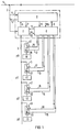
- the line 2 is led to the electricity meter Z, which is designed as a pulse generator.
- the line 3 after the electricity meter Z is used to supply electrical devices 10 to 13 in the apartment in question.
- Each of these electrical devices 10 to 13 is preceded by a switching element s0 to s3 for switching these devices on and off.
- These electrical devices 10 to 13 are assigned priority values p0 to p3 by the consumer of electrical energy living in this apartment.
- the device 10 has the lowest priority p0, the device 13 the highest priority p3.
- priorities p0 to p3 define a framework for the switching-off sequence of the electrical devices, which the customer perceives as tolerable, in such a way that the device which appears to be the least important to the customer is assigned the lowest priority p0 and the device 13 which is felt to be the least dispensable has the highest priority p3.
- a hot water tank can be considered as the device with the lowest priority, and the "device" with the highest priority can be considered, for example, the electrical lighting or the supply of the television set.
- the system for controlling the electrical energy consumption in this apartment includes, in addition to the electricity meter Z and the switching elements s0 to s3, one of the two-way communication between the electricity supply company and the individual household, the transceiver unit T, which provides line 4 information in the form of data and receives commands from line 2 or sends them via line 5 to line 2 and thus emits them to the electricity supply company.
- the between the transceiver unit T and the electricity supply company Information to be exchanged can be encoded, for example, in the form of pulse images known from ripple control technology.
- the transmission of the meter reading for the purpose of tariff reading takes place from the electricity meter Z via line 6 to the transmitter-receiver unit T, where it is delivered to the feeding electrical network after coding via line 5.
- Tariff changeover commands received by the transceiver unit T are transmitted to the electricity meter Z via the line 7. All other information is preferably transmitted via the transceiver unit T to the load computer C or from the load computer C via the lines 8 and 9.
- the load computer C is preferably designed as a microcomputer with the associated functional units, such as clock generators, volatile and non-volatile memories, program memories and central units.
- This load computer has essential functions of a largely self-sufficient maximum monitor, which provides information about the duration of the measuring period and the measuring period input MP Via the line 10, a pulse train with a power proportional frequency is supplied by the electricity meter Z, which is designed as a pulse generator counter.
- the information transfer between the load computer C and the electricity meter Z is via the line 11, via which, for example, tariff changeover commands determined by the load computer C can be transmitted.
- the load computer C determines the corresponding actual power value for the individual measuring periods from the pulse sequence coming in via line 10 with a power proportional frequency and compares this with at least one actual power value present in the load computer.
- This at least one actual power value can either be permanently programmed or, depending on the result of a balance between the available power and the required power at the electricity supply company, can be made available to the load computer C via the transceiver unit T.
- the priorities assigned to the individual devices 10 to 13 by the consumer of electrical energy are also arranged in a priority sequence, as well as information about the specific properties of the devices in the form of the temporal behavior of these devices in relation to Time constants reflecting switch-ons are available.
- the load computer C receives current operating data of the individual devices 10 to 13 via the lines 12 to 15 in the form of the currents flowing to the devices 10 to 13 or the switching state of the associated switching elements s0 to s3.
- the load computer C can be set up to pre-calculate the power maximum to be expected during each current measuring period on the basis of the power actual value supplied by the electricity meter Z in the form of the pulse train with a power proportional frequency.
- This advance calculation can also include the switching behavior to be expected under the effect of a frequently used self-sufficient two-point control of individual electrical devices.
- the load computer C determines the shutdown of individual devices that is least detrimental to the individual consumer for the relevant consumer of electrical energy in a largely self-sufficient manner from interventions by the electricity supply company, if this appears necessary due to a required power limitation.
- the electricity supply company Useful intervention options, for example by specifying performance limit values or activating individual programs that moderate performance consumption i m load computer.
- the electricity supply company can transmit an emergency shutdown command, which is executed by the load computer C. This command can be of the type that either switches off all devices or switches off devices up to a certain priority level.
- the switching elements s0 to s3 exhibit bistable behavior and are both manually operable and switchable in each of their two stable states by means of electrical signals at at least one control input. These signals causing the switching action are generated in the load computer C and transmitted to the switching elements via lines 16 to 19.
- the lines 16 to 19 between the load computer C and the switching elements s0 up to s3 require a certain installation effort. This can be avoided if the installed electrical network, ie line 3, is used to transmit the signals which trigger the switching operations of the switching elements.
- the signals associated with the individual switching elements mS to s3 are transmitted directly to line 3 for carrying out switching operations after corresponding coding, so that they are recognized by the individual switching elements s0 to s3 and are passed on to the corresponding switching element for triggering the switching action can.
- the switching commands can therefore be transmitted, for example, using the pulse spacing method or the pulse pattern method.
- the corresponding coding can also be adopted by the load computer.
- each switching element is provided with a locking device which precludes manual reclosure and which can be activated by a corresponding control signal.
- each of the switching elements s0 to s3 contains a tripping coil which effects the shutdown and which receives permanent excitation in the event of an emergency shutdown.
- a sensor 20 to 23 is provided in each of the switching elements s0 to s3.
- an overcurrent release can be installed in each of the switching elements s0 to s3 to protect against overload. This offers the possibility that the current-carrying element of the overcurrent release is used at the same time as a sensor of the current flowing to the associated device 10 to 13 by the voltage drop occurring on this element is reported back via lines 12 to 15 to the load computer C.
- the information about the constant current or power consumption is to be stored in a non-volatile memory of the load computer.
- Devices with non-constant power consumption are those that have a complicated work cycle with different work processes, for example washing machines. In this case, it is sufficient to report back only the power-intensive work processes to the load computer C.
- the sensor for the current flowing to the device is to be followed by a limit indicator, the output signal of which is only active during high-power workflows of the work cycle.
- the tariff changeover of the electricity meter Z initiated by the load computer C via the line 11 can be triggered in a load computer which is set up to calculate the expected maximum power in advance if the forward calculation of the expected maximum power allows the limit value to be expected to be exceeded.
- the electricity meter Z and the load computer can be designed as an integrated unit.
- the transmitter-receiver unit T can also be included in this integrated unit.
- the microcomputer can also take over functions of the electricity meter Z and of the transceiver unit T. This is indicated by the dash-dotted outline of blocks C, Z, T.
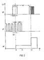
- FIG. 2 shows an example of a modification of the priority sequence when devices are switched off due to the mode of operation of the load computer.
- the abscissa of the diagram in FIG. 2 represents a time axis, the ordinate represents the devices current or device performance.
- the top line shows the power draw of an electrical device with the lowest priority p0
- the middle row shows the power draw of a device with the next higher priority p1
- the bottom line shows the power draw of a device with the higher priority p2.
- the actual power value exceeds the specified power limit.
- the device with the priority p0 would be shutdown in this case regardless of its technical properties and history.
- the operation of the device with priority p0 is continued and instead the device with priority p1 is switched off.
- the load computer C contains information about the time constants or the switch-on and switch-off times te0, te1 or ta0, ta1 that occur in regular two-point operation and, moreover, it can be seen from the recording of the last current flow periods ⁇ tO and ⁇ t1 that the device with the priority p0 is only just beginning has slightly more than half of its on-time required, whereas the device with priority p1 has already been supplied with power for almost its entire on-time, contrary to the priority sequence programmed per se, the least possible impairment for the consumer of electrical energy by switching off the device priority p1 reached.
- the device with priority p1 goes out of operation.
- This device can be, for example, an air conditioning system in cooling mode, the operation of which is superfluous due to cooling in the evening.
- the device with priority p2 starts a very performance-intensive workflow as part of its working cycle, so that the power limit value is exceeded again. In this case maintain the programmed priority sequence, the device with the lowest priority p0 not being switched off but operated with reduced power by being switched on and off periodically at a high clock frequency for the rest of its duty cycle.
Landscapes
- Engineering & Computer Science (AREA)
- Power Engineering (AREA)
- Physics & Mathematics (AREA)
- General Physics & Mathematics (AREA)
- Supply And Distribution Of Alternating Current (AREA)
- Brushes (AREA)
- Confectionery (AREA)
- Control Of Electric Motors In General (AREA)
Priority Applications (1)
| Application Number | Priority Date | Filing Date | Title |
|---|---|---|---|
| AT83106516T ATE44417T1 (de) | 1982-07-15 | 1983-07-04 | System zur steuerung des elektrischen energieverbrauchs, vorzugsweise in haushalten. |
Applications Claiming Priority (2)
| Application Number | Priority Date | Filing Date | Title |
|---|---|---|---|
| DE3226544 | 1982-07-15 | ||
| DE19823226544 DE3226544A1 (de) | 1982-07-15 | 1982-07-15 | System zur steuerung des elektrischen energieverbrauchs, vorzugsweise in haushalten |
Publications (3)
| Publication Number | Publication Date |
|---|---|
| EP0099043A2 true EP0099043A2 (fr) | 1984-01-25 |
| EP0099043A3 EP0099043A3 (en) | 1986-05-14 |
| EP0099043B1 EP0099043B1 (fr) | 1989-07-05 |
Family
ID=6168528
Family Applications (1)
| Application Number | Title | Priority Date | Filing Date |
|---|---|---|---|
| EP83106516A Expired EP0099043B1 (fr) | 1982-07-15 | 1983-07-04 | Système pour commander la consommation d'énergie électrique, de préférence pour l'usage domestique |
Country Status (3)
| Country | Link |
|---|---|
| EP (1) | EP0099043B1 (fr) |
| AT (1) | ATE44417T1 (fr) |
| DE (2) | DE3226544A1 (fr) |
Cited By (8)
| Publication number | Priority date | Publication date | Assignee | Title |
|---|---|---|---|---|
| EP0198222A3 (fr) * | 1985-03-12 | 1988-08-31 | Micro Logic Gesellschaft für rechnergesteuerte Systeme mbH | Procédé de répartition de puissance |
| EP0620631A1 (fr) * | 1993-04-15 | 1994-10-19 | ZELTRON S.p.A. | Système de contrôle pour appareils électroménagers |
| EP0660486A1 (fr) * | 1993-12-23 | 1995-06-28 | ZELTRON S.p.A. | Procédé de détermination de positions sur la terre correspondant aux changements observés de la distance de satellite |
| EP0607739A3 (fr) * | 1992-12-22 | 1995-08-02 | Niessen Sa | Système de guidage pour des appareils électroménagers. |
| FR2719440A1 (fr) * | 1994-04-28 | 1995-11-03 | Delta Dore | Appareil de contrôle d'une installation électrique d'une habitation particulière. |
| WO1999022286A1 (fr) * | 1997-10-24 | 1999-05-06 | Robert Bosch Gmbh | Interrupteur destine a la commande de consommateurs electriques |
| WO2000059092A1 (fr) * | 1999-03-26 | 2000-10-05 | Broemsel Sven | Procede et systeme permettant de determiner une quantite d'energie necessitee ou consommee par un consommateur |
| WO2004023624A1 (fr) * | 2002-09-05 | 2004-03-18 | Dynagen Technologies Inc. | Systeme et procede servant a gerer une charge de puissance |
Families Citing this family (10)
| Publication number | Priority date | Publication date | Assignee | Title |
|---|---|---|---|---|
| DE4019523A1 (de) * | 1990-06-19 | 1992-01-09 | Decher Dieter | Anordnung zum steuern des stromverbrauchs eines abnehmers |
| DE4023846C2 (de) * | 1990-07-27 | 1998-09-10 | Aeg Hausgeraete Gmbh | Steuereinheit für eine Waschmaschine und einen Trommelwäschetrockner |
| DE4109928C2 (de) * | 1991-03-26 | 1998-02-26 | Muenster Stadtwerke | Vorrichtung zum Messen der Leistungsaufnahme einer Mehrzahl von elektrischen Verbrauchseinheiten |
| DE29714767U1 (de) * | 1997-08-18 | 1999-01-21 | Siemens AG, 80333 München | Netzleitanordnung |
| DE19827345B4 (de) * | 1998-06-19 | 2005-04-14 | Fünfgeld, Christian, Dipl.-Ing. | Verfahren zur Ableitung der Wirkleistung elektrischer Verbraucher |
| DE10009325A1 (de) * | 2000-02-22 | 2001-08-23 | Deutsche Telekom Ag | Verfahren zur Überwachung der Leistungsbilanz in einem Energieversorgungsnetz und hierfür geeignetes Überwachungssystem |
| DE102004002189A1 (de) * | 2004-01-16 | 2005-08-04 | EMH Elektrizitätszähler GmbH & Co. KG | Elektronischer Elektrizitätszähler bzw. Rundsteuerempfänger für Elektrizitätszähler |
| DE102004053709A1 (de) * | 2004-11-03 | 2006-05-04 | Schneck, Katrin, Dr. | Vorrichtung und Verfahren zur Fernsteuerung elektrischer Energieverbraucher |
| DE102005020519B4 (de) * | 2005-04-29 | 2009-03-12 | Miele & Cie. Kg | Haushaltgerät mit einer Steuereinrichtung und Verfahren zum Betreiben eines Haushaltgerätes |
| DE102008040272B4 (de) | 2008-07-09 | 2025-12-04 | Robert Bosch Gmbh | Steuereinrichtung und Verfahren zum Steuern eines an eine Energieversorgung angeschlossenen Geräts |
Family Cites Families (5)
| Publication number | Priority date | Publication date | Assignee | Title |
|---|---|---|---|---|
| US3906242A (en) * | 1974-08-16 | 1975-09-16 | Megatherm Corp | Computerized peak-shaving system for alleviating electric utility peak loads |
| DE2708883A1 (de) * | 1977-02-25 | 1978-08-31 | Heliowatt Werke | Elektronischer maximumwaechter |
| US4181950A (en) * | 1977-09-30 | 1980-01-01 | Westinghouse Electric Corp. | Adaptive priority determination power demand control method |
| GB2043371B (en) * | 1979-02-21 | 1983-05-25 | South Eastern Elec Board | Load shedding |
| US4347576A (en) * | 1980-04-28 | 1982-08-31 | Honeywell Inc. | Load management control apparatus with improved duty cycle operation |
-
1982
- 1982-07-15 DE DE19823226544 patent/DE3226544A1/de not_active Withdrawn
-
1983
- 1983-07-04 AT AT83106516T patent/ATE44417T1/de not_active IP Right Cessation
- 1983-07-04 DE DE8383106516T patent/DE3380147D1/de not_active Expired
- 1983-07-04 EP EP83106516A patent/EP0099043B1/fr not_active Expired
Cited By (8)
| Publication number | Priority date | Publication date | Assignee | Title |
|---|---|---|---|---|
| EP0198222A3 (fr) * | 1985-03-12 | 1988-08-31 | Micro Logic Gesellschaft für rechnergesteuerte Systeme mbH | Procédé de répartition de puissance |
| EP0607739A3 (fr) * | 1992-12-22 | 1995-08-02 | Niessen Sa | Système de guidage pour des appareils électroménagers. |
| EP0620631A1 (fr) * | 1993-04-15 | 1994-10-19 | ZELTRON S.p.A. | Système de contrôle pour appareils électroménagers |
| EP0660486A1 (fr) * | 1993-12-23 | 1995-06-28 | ZELTRON S.p.A. | Procédé de détermination de positions sur la terre correspondant aux changements observés de la distance de satellite |
| FR2719440A1 (fr) * | 1994-04-28 | 1995-11-03 | Delta Dore | Appareil de contrôle d'une installation électrique d'une habitation particulière. |
| WO1999022286A1 (fr) * | 1997-10-24 | 1999-05-06 | Robert Bosch Gmbh | Interrupteur destine a la commande de consommateurs electriques |
| WO2000059092A1 (fr) * | 1999-03-26 | 2000-10-05 | Broemsel Sven | Procede et systeme permettant de determiner une quantite d'energie necessitee ou consommee par un consommateur |
| WO2004023624A1 (fr) * | 2002-09-05 | 2004-03-18 | Dynagen Technologies Inc. | Systeme et procede servant a gerer une charge de puissance |
Also Published As
| Publication number | Publication date |
|---|---|
| ATE44417T1 (de) | 1989-07-15 |
| DE3226544A1 (de) | 1984-01-19 |
| EP0099043B1 (fr) | 1989-07-05 |
| EP0099043A3 (en) | 1986-05-14 |
| DE3380147D1 (en) | 1989-08-10 |
Similar Documents
| Publication | Publication Date | Title |
|---|---|---|
| EP0099043B1 (fr) | Système pour commander la consommation d'énergie électrique, de préférence pour l'usage domestique | |
| DE69333596T2 (de) | Steuerungssystem für die Energieverteilung | |
| DE102008057563B4 (de) | Verfahren und Vorrichtung zum netzkonformen Betreiben einer Mehrzahl von dezentralen mit Verbrauchern/Erzeugern von elektrischer Energie versehenen und an ein elektrisches Niederspannungsnetz angeschlossenen Einheit | |
| DE102004029331A1 (de) | Zentrales Steuerungssystem für Klimaanlagen und Verfahren zum Betreiben desselben | |
| WO2012000538A1 (fr) | Mise en marche de terminaux en fonction de la charge réseau | |
| EP2695269A1 (fr) | Gestion de charge optimisée | |
| DE112011102128T5 (de) | Elektrizitätsmanagementsystem zum effektiven Betreiben einer Mehrzahl von Elektrogeräten, Elektrogerät dafür, zentrale Steuereinheit, Computerprogramm und Speichermedium dafür sowie Verfahren zum Managen von Elektrogeräten mittels der zentralen Steuereinheit | |
| EP2151032B1 (fr) | Procédé d'exploitation d'un système comportant au moins un dispositif répartiteur d'énergie | |
| EP2875560B1 (fr) | Procédé de réglage du rapport entre l'énergie électrique injectée et prélevée dans un réseau d'alimentation en énergie électrique | |
| EP2476984B1 (fr) | Appareil de réfrigération et/ou de congélation | |
| DE19842043B4 (de) | Verfahren zur automatischen und verbraucherorientierten Minimierung des Gesamtstromverbrauchs und der Leistungsspitze einer Gruppe von an einem Leistungsversorgungsnetz angeschlossenen einzelnen elektrischen Verbrauchern | |
| DE102007043888B4 (de) | Vorrichtung zur Versorgung eines Verbrauchers | |
| EP0464423B1 (fr) | Dispositif pour commander la consommation totale d'énergie d'un récepteur de courant | |
| EP0268697A1 (fr) | Procédé et système pour la réduction de pointes de puissance pour des puissances de distribution et d'évacuation attachées à des conduites | |
| DE4432745C1 (de) | Verfahren für den Betrieb einer Speicherheizgerätesteuerung | |
| WO2012048787A2 (fr) | Système de gestion de charge et procédé de gestion de charge pour des consommateurs électriques | |
| EP0667968B1 (fr) | Procede et dispositif permettant de minimiser la consommation en energie d'une charge electrique | |
| EP1072081B1 (fr) | Procede de reglage de la puissance totale d'une installation electriques, particulierement d'un groupe de consommateurs d'energie | |
| DE202021002165U1 (de) | Waschmaschine mit Leistungsanpassung zur Eigenverbrauchsmaximierung bei lokaler regenerativer Stromerzeugung | |
| EP2444765B1 (fr) | Système comprenant au moins un appareil de refroidissement et/ou de congélation | |
| DE69505634T2 (de) | Elektrisches System mit Steuerung des Leistungsbedarfs | |
| DE102004032618A1 (de) | Solar-Funk-Temperatursensor | |
| EP2728707A2 (fr) | Dispositif d'alimentation électrique de secours | |
| DE69933748T2 (de) | Verfahren zur Steuerung der Last mindestens einer Heizvorrichtung, insbesondere eines elektrischen Wärmespeichers, und/oder der thermischen Kapazität der Konstruktionsteile und der Ausrüstung; Vorrichtung zur Durchführung des Verfahrens | |
| EP2594858A1 (fr) | Procédé et système de télécommande de climatisations individuelles décentralisées sans interface de mise en réseau |
Legal Events
| Date | Code | Title | Description |
|---|---|---|---|
| PUAI | Public reference made under article 153(3) epc to a published international application that has entered the european phase |
Free format text: ORIGINAL CODE: 0009012 |
|
| AK | Designated contracting states |
Designated state(s): AT CH DE GB LI SE |
|
| PUAL | Search report despatched |
Free format text: ORIGINAL CODE: 0009013 |
|
| AK | Designated contracting states |
Kind code of ref document: A3 Designated state(s): AT CH DE GB LI SE |
|
| 17P | Request for examination filed |
Effective date: 19860728 |
|
| 17Q | First examination report despatched |
Effective date: 19880420 |
|
| GRAA | (expected) grant |
Free format text: ORIGINAL CODE: 0009210 |
|
| AK | Designated contracting states |
Kind code of ref document: B1 Designated state(s): AT CH DE GB LI SE |
|
| REF | Corresponds to: |
Ref document number: 44417 Country of ref document: AT Date of ref document: 19890715 Kind code of ref document: T |
|
| REF | Corresponds to: |
Ref document number: 3380147 Country of ref document: DE Date of ref document: 19890810 |
|
| GBT | Gb: translation of ep patent filed (gb section 77(6)(a)/1977) | ||
| PLBE | No opposition filed within time limit |
Free format text: ORIGINAL CODE: 0009261 |
|
| STAA | Information on the status of an ep patent application or granted ep patent |
Free format text: STATUS: NO OPPOSITION FILED WITHIN TIME LIMIT |
|
| 26N | No opposition filed | ||
| EAL | Se: european patent in force in sweden |
Ref document number: 83106516.4 |
|
| PGFP | Annual fee paid to national office [announced via postgrant information from national office to epo] |
Ref country code: GB Payment date: 19960621 Year of fee payment: 14 Ref country code: AT Payment date: 19960621 Year of fee payment: 14 |
|
| PGFP | Annual fee paid to national office [announced via postgrant information from national office to epo] |
Ref country code: SE Payment date: 19960723 Year of fee payment: 14 |
|
| PGFP | Annual fee paid to national office [announced via postgrant information from national office to epo] |
Ref country code: DE Payment date: 19960917 Year of fee payment: 14 |
|
| PGFP | Annual fee paid to national office [announced via postgrant information from national office to epo] |
Ref country code: CH Payment date: 19961017 Year of fee payment: 14 |
|
| PG25 | Lapsed in a contracting state [announced via postgrant information from national office to epo] |
Ref country code: GB Free format text: LAPSE BECAUSE OF NON-PAYMENT OF DUE FEES Effective date: 19970704 Ref country code: AT Free format text: LAPSE BECAUSE OF NON-PAYMENT OF DUE FEES Effective date: 19970704 |
|
| PG25 | Lapsed in a contracting state [announced via postgrant information from national office to epo] |
Ref country code: SE Effective date: 19970705 |
|
| PG25 | Lapsed in a contracting state [announced via postgrant information from national office to epo] |
Ref country code: LI Free format text: LAPSE BECAUSE OF NON-PAYMENT OF DUE FEES Effective date: 19970731 Ref country code: CH Free format text: LAPSE BECAUSE OF NON-PAYMENT OF DUE FEES Effective date: 19970731 |
|
| GBPC | Gb: european patent ceased through non-payment of renewal fee |
Effective date: 19970704 |
|
| REG | Reference to a national code |
Ref country code: CH Ref legal event code: PL |
|
| PG25 | Lapsed in a contracting state [announced via postgrant information from national office to epo] |
Ref country code: DE Free format text: LAPSE BECAUSE OF NON-PAYMENT OF DUE FEES Effective date: 19980401 |
|
| EUG | Se: european patent has lapsed |
Ref document number: 83106516.4 |