EP0099077B1 - Appareil d'électrode foetal - Google Patents
Appareil d'électrode foetal Download PDFInfo
- Publication number
- EP0099077B1 EP0099077B1 EP83106669A EP83106669A EP0099077B1 EP 0099077 B1 EP0099077 B1 EP 0099077B1 EP 83106669 A EP83106669 A EP 83106669A EP 83106669 A EP83106669 A EP 83106669A EP 0099077 B1 EP0099077 B1 EP 0099077B1
- Authority
- EP
- European Patent Office
- Prior art keywords
- sleeve
- guide tube
- fetal
- piston
- body member
- Prior art date
- Legal status (The legal status is an assumption and is not a legal conclusion. Google has not performed a legal analysis and makes no representation as to the accuracy of the status listed.)
- Expired
Links
Images



Classifications
-
- A—HUMAN NECESSITIES
- A61—MEDICAL OR VETERINARY SCIENCE; HYGIENE
- A61B—DIAGNOSIS; SURGERY; IDENTIFICATION
- A61B5/00—Measuring for diagnostic purposes; Identification of persons
- A61B5/43—Detecting, measuring or recording for evaluating the reproductive systems
- A61B5/4306—Detecting, measuring or recording for evaluating the reproductive systems for evaluating the female reproductive systems, e.g. gynaecological evaluations
- A61B5/4343—Pregnancy and labour monitoring, e.g. for labour onset detection
- A61B5/4362—Assessing foetal parameters
-
- A—HUMAN NECESSITIES
- A61—MEDICAL OR VETERINARY SCIENCE; HYGIENE
- A61B—DIAGNOSIS; SURGERY; IDENTIFICATION
- A61B5/00—Measuring for diagnostic purposes; Identification of persons
- A61B5/24—Detecting, measuring or recording bioelectric or biomagnetic signals of the body or parts thereof
- A61B5/25—Bioelectric electrodes therefor
- A61B5/279—Bioelectric electrodes therefor specially adapted for particular uses
- A61B5/28—Bioelectric electrodes therefor specially adapted for particular uses for electrocardiography [ECG]
- A61B5/283—Invasive
- A61B5/288—Invasive for foetal cardiography, e.g. scalp electrodes
Definitions
- the invention relates to an apparatus for use in monitoring fetal vital signs with monitoring equipment insertable through the vagina and cervix of a woman in labor into a fetal scalp.
- fetal physiological signals such as heart rate, pH and the like so as to be aware of the physical condition of the fetus. If the fetus is in distress, it can be delivered immediately by a caesarian section. Devices attached externally to the mother's body have proven inadequate for monitoring of the fetus because they cannot distinguish clearly the fetal heart rate from that of the mother.
- a forcep type electrode device has been used to obtain fetal heart rate.
- the forcep electrode device usually has pincher electrode clips secured to a plug which is placed at the end of a guide tube.
- the forcep electrode device is inserted through the passages of a woman in labor by the guide tube, and the clips are squeezed onto the fetal scalp.
- the guide tube is removed and the clips are connected to monitoring equipment by insulated wires.
- the clips are very brittle and are often cracked or damaged during application.
- the clips also are not rigidly positioned on the fetal scalp and can pivot about an axis defined by their points of fixation.
- a spiral fetal electrode device has been used to obtain fetal heart rate readings.
- the device has one or two helical coils attached to a plug which in turn is mounted on the end of a flexible drive tube.
- An outer insertion tube slides around the drive tube.
- the mother's tissues may be damaged or the mother's heartbeat may be read on the monitoring device rather than that of the fetus.
- the fragile helical coils occasionally break while being embedded within the fetal scalp.
- the spiral fetal electrode device is not removed by carefully counter rotating the helical coils from the fetal scalp, significant trauma and injury can result. By the ripping of the fetal scalp due to improper removal of the spiral electrode, the fetus may sustain a serious scalp wound with significant bleeding and the newborn may become susceptible to infection.
- a fetal electrode apparatus with a helical electrode driven by a plunger is disclosed in US-A-4 321 931.
- EP-Al-0 004 510 discloses another fetal electrode apparatus in which an electrode can be exposed or retracted in a measuring head by translational movement in a flexible tube.
- the aim of this invention to provide an improved bipolar fetal electrode apparatus in which the disadvantages of the prior art are successfully avoided and to provide an electrode instrument effecting firm, stable contact with the fetal scalp while minimizing trauma to the mother and child during insertion or removal of the apparatus.
- an apparatus of the kind mentioned before which comprises a form-sustaining guide tube having a forward end portion and adapted to be inserted through the vagina and cervix of the woman in labor;
- a sleeve having a rearward end portion which is disposed about the forward end portion of the guide tube, the sleeve being configured to allow slideable movement of the forward end portion of the guide tube within the sleeve;
- a piston slideably disposed within the sleeve for releasably engaging the forward end portion of the guide tube
- a body member including:
- the apparatus is inserted through the woman's passages and the fetal electrode structure contacts the fetal scalp.
- the guide tube slideably advances in the sleeve and releasably contacts the piston member. Due to this action, the piston slides forward within the sleeve and the active fetal electrodes advance forward through and out of the channels with an outward curvature of a predetermined radius.
- the active fetal electrodes pierce the fetal scalp and generally advance outwardly along the plane of the scalp to effect firm, electrically conductive contact therewith.
- a reference electrode is mounted on the piston and means are provided for electrically connecting the reference electrode to the monitoring equipment.
- the piston is a head member or especially a cylinder member dimensioned to slideably advance within the sleeve along the longitudinal axis of the sleeve upon contact with and advancement of the guide tube .in the sleeve.
- the head member defines a cavity having an opening adjacent the body member.
- the piston also includes a cylindrical retainer cap adjacent the forward end portion of the guide tube for releasable contact therewith. The retainer cap is secured to the head member.
- the rearward portion of the body member is a housing having an outer surface configured and dimensioned to fit within the cavity of the cylinder member in substantially sealed tight relation therewith.
- the housing also has a frustoconical inner wall with slots defining the channels.
- the forward portion of the body member is a plug member having a frustoconical outer wall for mating engagement with the inner wall of the housing.
- the active electrodes there are four active electrodes and four channels passing through the body member.
- the active electrodes have free end portions which terminate in a beveled tip to facilitate- piercing the fetal scalp.
- the channels are so defined by the slots in the inner wall-of the housing such that the electrodes advance within the slots and exit the forward portion of the body member in a direction substantially parallel to the fetal scalp.
- the reference electrode comprises a flat metal disk secured to the piston between the cylinder and the retainer cap member.
- the sleeve has an inner surface adjacent to the guide tube with a multiplicity of projecting members such as ribs projecting radially inwardly so as to slideably contact the outer surface of the guide tube.
- the insertion device also includes means for advancing the guide tube along the longitudinal axis of the sleeve by a predetermined distance in either direction.
- the invention thus provides a safe and simple fetal electrode apparatus for attaching onto a fetal scalp and subsequently removing the instrument without endangering the fetus.
- the fetal electrode instrument thus reduces the danger of excess bleeding and infection.
- the inventive fetal electrode instrument While fixedly mounted to the fetal scalp, the inventive fetal electrode instrument possesses significant stability to overcome external forces acting upon the electrode due to the movement of the fetus or mother.
- the active fetal electrodes are in significantly increased contact with the scalp yet do not injure the fetal scalp. With all these conditions, accurate measuring signals of the fetal heart rate are obtained.
- fetal electrode structure 12 is removably disposed within sleeve 10 and sleeve 10 slideably surrounds end portion 6 of guide tube 4.
- Lead wires 14 are electrically connected to fetal electrode structure 12. The lead wires pass through sleeve 10 and guide tube 4, out rearward end portion 8 and electrically connect to fetal monitoring equipment (not shown).
- Guide tube 4 is appproximately 30 cm long and sleeve 10 is approximately 3 cm long.
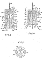
- fetal electrode structure 12 having a displaceable piston 16 with a retainer cap 18 and a cylinder member 20; a reference electrode 22; a body member 24 with a housing 26, a plug member 28 and four channels 32; four active fetal electrodes 34 and two insulated wires 14.
- Fig. 2 also shows sleeve 10 and forward portion 6 of guide tube 4 in releasable contact with retainer cap 18.
- retainer cap 18 has a cylindrical configuration with a central opening (similar to a washer) through which pass lead wires 14.
- Reference electrode 22 has a disk-like configuration with a central opening and a slot 38 (similar to a slotted washer). Reference electrode 22 is positioned on cylinder member 20 to surround a surface extension 36. One of electrical lead wires 14 is soldered to reference electrode 22 in slot 38 for effecting electrical contact with the monitoring equipment.
- Retainer cap 18 is ultrasonically welded or glued to surface extension 36. Retainer cap 18 secures reference electrode 22 between retainer cap 18 and cylinder member 20.
- Cylinder member 20 there is defined a hollow cavity 40 in which at least an upper portion 42 of housing 26 can be slideably disposed. Cylinder member 20 also has four passages 44 through which pass and in which are retained the four active fetal electrodes 34. Piston 16 is configured and dimensioned to slide within sleeve 10 along the longitudinal axis of the sleeve.
- the upper portion 42 of housing 26 is configured and dimensioned to slideably engage an inner wall 48 of cylinder member 20 so that cylinder member 20 can advance forward along the longitudinal axis of sleeve 10 and surround upper portion 42 to effect a sealed tight relation between cylinder member 20 and housing 26.
- Cylinder member 20 advances along upper portion 42 until end 50 of cylinder member 20 contacts surface 52 of body member 24.
- the sealed tight relation of cylinder member 20 with housing 26 precludes body fluids of the mother from entering cavity 40' and causing a grounding of active fetal electrodes 34 with reference electrode 22.
- Housing 26 has an inner wall 54 with a frustoconical curved configuration. More specifically, inner wall 54 tapers radially outwardly from an internal face 55 as it advances to an external face 56 at a curvature of a predetermined radius. Inner wall 54 has four slots which follow the configuration of the inner wall from internal face 55 to external face 56. The four slots are arranged on external face 56 around an axis of radial symmetry. Plug member 28 has an outer wall 57 with a frustoconical curved configuration of the same radius as that of inner wall 54 of housing 26 so that inner wall 54 and outer wall 57 engage in mating relation. Inner wall 54 and the slots in outer wall 57 thereby define channels 32. Plug member 28 includes an integral snap ring 58 which snaps plug member 28 into housing 26. Alternatively, plug 28 can be ultrasonicially welded or glued to housing 26.
- four active fetal electrodes 34 are made from two flexible, resilient U-shaped wires 59 and 60 which pass through cylinder member 20 via passages 44 and are soldered together along with one of lead wires 14 at position 61. Active fetal electrodes 34 are fixedly retained within piston 16 by retainer cap 18. Each of the four active electrodes 34 have free ends 62 which pass through opening 63 in housing 26. Each active electrode 34 enters its own channel 32 and follow the configuration of the channel through housing 26. As seen in Fig. 3, in the loaded or retracted position, free end 62 of each active fetal electrode 34 terminates within body member 24. As seen in Fig.
- free ends 62 of active fetal electrodes 34 project out from external face 56 by a distance "d” and have a sharp beveled tip 64 for facilitating piercing a fetal scalp.
- the flat surface of beveled tip 64 projects toward the fetal scalp (not shown) with the point projecting outwardly to further effect outward advancement of the electrodes in a plane substantially parallel to the fetal scalp.
- Fig. 6 there are disclosed the various elements of fetal electrode apparatus 2. There are shown guide tube 4, sleeve 10, retainer cap 18, reference electrode 22, active fetal electrodes 34, cylinder member 20, housing 26 and plug member 28.
- forward end portion 6 of guide tube 4 releasably engages an inner surface 66 of sleeve 10 along ribs 68.
- Forward portion 6 of guide tube 4 slides within sleeve 10 along the longitudinal axis of sleeve 10 and releasably contacts an upper surface 72 of retainer cap 18.
- the dimensions of forward portion 70 and inner surface 66 are such that sliding therebetween is possible yet guide tube 4 preferably can be secured to sleeve 10.
- Sleeve 10 has a forward end portion 74 which releasably surrounds a portion of housing 26 and releasably engages an upper surface 76 of flange or rim 78 or housing 26. Accordingly, at least a portion of housing 26 is releasably secured within sleeve 10 and the housing is precluded from moving more than a predetermined distance within sleeve 10 toward piston member 16 due to contact of forward end portion 74 with flange 78.
- guide tube 4 and sleeve 10 preferably are made of synthetic plastic resins such as polyethylene.
- Retainer cap 18, housing 26 and plug member 28 preferably are made of synthetic plastic resins such as a machinable, injection moldable or extrudable polymers (e.g., nylon, polyvinyl chloride or acetals).
- reference electrode 22 is made of an electrically conductive, non-corrosive, non-toxic material such as stainless steel.
- active fetal electrodes 34 are made of electrically conductive, non-corresive, non-toxic resilient materials such as spring stainless steel alloys.
- the same material is utilized for the reference electrode and the active fetal electrodes.
- fetal electrode apparatus 2 of the present invention is illustrated with reference to the drawings, particularly Figs. 1,2,7 7 and 8.
- a doctor loads lead wires 14 and fetal electrode structure 12 through sleeve 10 such that insulated lead wires 14 pass through guide tube 4 and exit rearward position 8 thereof.
- active fetal electrodes 34 extend out of body member 24, the doctor tugs on insulated wires 14 in a direction along guide tube 4 away from fetal electrode structure 12.
- Upper wall 76 of flange 78 thus releasably engages forward end portion 74 or sleeve 10.
- the active electrodes 34 in turn are pulled along in this direction and their free ends 62 are withdrawn within body member 24 so that they do not extend out of face 56. This loaded or retracted position is shown in Figs. 1, 2 and 3.
- the doctor inserts forward section 6 of guide tube 4 through the mother's vagina 80 and cervix 82 as shown in Fig. 7.
- Fetal electrode structure 12 then is brought in contact with fetus 84.
- the doctor exerts a forward pressure along the longitudinal axis of guide tube 4 in a direction toward fetus 84. Consequently, forward portion6 of guide tube 4 advances and releasably contacts retainer cap 18.
- retainer cap 18 and in turn upon cylinder member 20 which contains active fetal electrodes 34
- retainer cap 18 and cylinder 20 slide forward within sleeve 10. Consequently, electrodes 34 advance through channels 32, out of openings 86 of face 56 and into the fetal scalp. Due to the predetermined radius of channels 32, the presence of beveled tip 64 of active fetal electrodes 34 and fetal skin resistance, the flexible electrodes generally advance in an outwardly direction substantially parallel to the fetal scalp.
- Fetal electrode apparatus 2 now is in the fully released or extended position as seen in Fig. 4. That is, end 50 of cylinder member 20 has contacted surface 52 of housing 26 and active fetal electrodes 34 have advanced into the fetal scalp as far as permitted by the fetal electrode structure 12. For operability of fetal electrode apparatus 2, however, active fetal electrodes 34, do not have to be fully extended and inserted into the fetal scalp provided some contact with the scalp is maintained.
- channels 32 and body member 24 surround the non-extended portions of active electrode 34 to preclude contact with the mother's fluids and grounding out with reference electrode 22.
- the doctor exerts a rearward pressure on guide tube 4 in a direction away from fetus 84, and slides guide tube 4 together with sleeve 10 off of wires 14 leaving only fetal electrode structure 12 and wires 14 in the mother and attached to fetus 84.
- the free ends of lead wires 14 are then connected to suitable equipment for monitoring fetal heart rate (not shown).
- fetal electrode structure 12 Prior to actual delivery of the baby, it usually is desirable to remove fetal electrode structure 12 from fetus 84. This is accomplished in a simple, non-traumatic manner.
- the doctor grabs and pulls lead wires 14 in a direction away from the fetus and the mother's passages 80 and 82 thus removing fetal electrode structure 12 from fetus 84.
- the force acting upon lead wire 14 acts upon piston 16 and upon active fetal electrodes 34 pulling both away from fetus 84. Since active fetal electrodes 34 are located within arcuate channels 32 of body member 24 and are resilient, body member 24 will move with the electrodes away from fetus 84 upon application of the force.
- active fetal electrodes 34 are flexible, they will withdraw from the fetal scalp along the same path through which they entered, thus effecting minimal trauma to the fetus. There will only remain four small puncture wounds in the fetal scalp through which the active fetal electrodes 34 originally entered.
- Figs. 9-11 disclose an insertion device for use with the present invention.
- the insertion device includes a guide tube 104 having a front end portion 106, a hollow coupling member or junction member 102 having flanges 105 and 107, and sleeve 110 having ribs 168.
- junction member 102 a rear end portion 108 is firmly secured (e.g., force fit, gluing, etc.) within forward end portion 106 of guide tube 104.
- Flange 105 of junction member 102 contacts the end wall of forward end portion 106.
- Flanges 105 and 107 are separated by a distance at least sufficient for ribs 168 to slide therebetween.
- flanges 105 and 107 are separated by a distance equal to the length of ribs 168 plus the distance (“d") active fetal electrodes 34 can extend out of fetal electrode structure 12.
- sleeve 110 with its ribs 168 are slid over flange 107 of junction member 102 to a position between flanges 105 and 107.
- ribs 168 do not extend the full length of sleeve 110 but terminate in the sleeve as seen in Fig. 9.
- end 114 of rib 168 is beveled toward the center of the sleeve to facilitate insertion of sleeve 110 about junction member 102 and flange 107.
- ribs 168 slide between flanges 105 and- 107 thus permitting sleeve 110 to move along member 102 by a predetermined distance in either direction along the axis of the sleeve.
- end 116 of rib 168 slideably contacts end wall 118 of flange 107 to preclude further movement of the sleeve in a direction away from the junction member.
- end 114 of sleeve 110 slideably contacts end wall 120 of flange 105 to preclude further movement of sleeve 110 in a direction toward guide tube 104.
- the method for using the insertion device of Figs. 9-11 in conjunction with inventive fetal electrode structure 12 of Figs. 2-4 is similar to that previously described with regard to Figs. 1, 2, 7 and 8.
- the doctor loads lead wires 14 and fetal electrode structure 12 (not shown in Figs. 9-11) into an end 174 of sleeve 110 such that lead wire 14 passes through junction member 102 and through and out a remote end (not shown) of guide tube 104.
- the doctor slides sleeve 110 in a forward direction toward fetal electrode structure 12 and away from guide tube 104. While grasping sleeve 110, the doctor tugs on insulated wires 14 in a direction along guide tube 104 away from fetal electrode structure 12.
- the doctor inserts forward end section 106 of guide tube 104 through the mother's vagina and cervix as shown in Fig. 7.
- fetal electrode structure 12 is attached to the fetus and the insertion device is thus brought to a released position as seen in Fig. 11.
- the insertion device is removed in a manner described previously with regards to Fig. 8.
- the slots which form channels 32 could be located in outer wall 57 of plug member 28 instead of in inner wall 54 of housing 26.
- An 0 ring could be secured around housing 26 between upper portion 42 and inner wall 48 to facilitate a sealed tight relation between housing 26 and cylinder member 20.
- Flange 78 on housing 26 may only project outwardly from housing 26 at certain locations instead of projecting around the entire circumference of housing 26, and forward end portion 74 of sleeve 10 may define slots to engage the modified flange 78.
- a pH electrode could be secured to plug member 28 and project toward the fetal scalp for contact therewith.
- junction member 102 could be formed as an integral part of forward portion 106 of guide tube 104.
Landscapes
- Health & Medical Sciences (AREA)
- Life Sciences & Earth Sciences (AREA)
- Medical Informatics (AREA)
- Molecular Biology (AREA)
- Pediatric Medicine (AREA)
- Biophysics (AREA)
- Pathology (AREA)
- Engineering & Computer Science (AREA)
- Biomedical Technology (AREA)
- Heart & Thoracic Surgery (AREA)
- Cardiology (AREA)
- Physics & Mathematics (AREA)
- Surgery (AREA)
- Animal Behavior & Ethology (AREA)
- General Health & Medical Sciences (AREA)
- Public Health (AREA)
- Veterinary Medicine (AREA)
- Pregnancy & Childbirth (AREA)
- Gynecology & Obstetrics (AREA)
- Reproductive Health (AREA)
- Measurement And Recording Of Electrical Phenomena And Electrical Characteristics Of The Living Body (AREA)
Claims (15)
Applications Claiming Priority (2)
| Application Number | Priority Date | Filing Date | Title |
|---|---|---|---|
| US399073 | 1982-07-16 | ||
| US06/399,073 US4501276A (en) | 1982-07-16 | 1982-07-16 | Fetal electrode apparatus |
Publications (3)
| Publication Number | Publication Date |
|---|---|
| EP0099077A2 EP0099077A2 (fr) | 1984-01-25 |
| EP0099077A3 EP0099077A3 (en) | 1984-07-18 |
| EP0099077B1 true EP0099077B1 (fr) | 1986-12-30 |
Family
ID=23578023
Family Applications (1)
| Application Number | Title | Priority Date | Filing Date |
|---|---|---|---|
| EP83106669A Expired EP0099077B1 (fr) | 1982-07-16 | 1983-07-07 | Appareil d'électrode foetal |
Country Status (4)
| Country | Link |
|---|---|
| US (1) | US4501276A (fr) |
| EP (1) | EP0099077B1 (fr) |
| JP (1) | JPS5964027A (fr) |
| DE (1) | DE3368504D1 (fr) |
Families Citing this family (51)
| Publication number | Priority date | Publication date | Assignee | Title |
|---|---|---|---|---|
| US4936306A (en) * | 1985-02-15 | 1990-06-26 | Doty James R | Device and method for monitoring evoked potentials and electroencephalograms |
| US4607644A (en) * | 1985-04-01 | 1986-08-26 | Cordis Corporation | Self-suturing porous epicardial electrode assembly |
| US4697598A (en) * | 1985-04-25 | 1987-10-06 | Westinghouse Electric Corp. | Evoked potential autorefractometry system |
| US4836208A (en) * | 1985-12-24 | 1989-06-06 | American Home Products Corporation (Del.) | Electrode assembly for sensing heart activity |
| US5237996A (en) * | 1992-02-11 | 1993-08-24 | Waldman Lewis K | Endocardial electrical mapping catheter |
| US5377677A (en) * | 1992-10-13 | 1995-01-03 | Graphic Controls Corporation | Packaging system for a fetal electrode |
| US5419322A (en) * | 1993-07-22 | 1995-05-30 | Joseph; Barry M. | Internal apparatus for continuous electrical and oximetric intrapartum monitoring of the fetus |
| US5388579A (en) * | 1993-09-23 | 1995-02-14 | Graphic Controls Corporation | Fetal electrode product with channeled drive mechanism and improved torque characteristics |
| US5474065A (en) * | 1994-04-04 | 1995-12-12 | Graphic Controls Corporation | Non-invasive fetal probe |
| US5833622A (en) * | 1994-04-04 | 1998-11-10 | Graphic Controls Corporation | Non-invasive fetal probe having improved mechanical and electrical properties |
| DE4418022A1 (de) * | 1994-05-19 | 1995-11-23 | Biotronik Mess & Therapieg | Endoskopisch einsetzbare Elektrodenanordnung |
| SE9402775D0 (sv) * | 1994-08-19 | 1994-08-19 | Siemens Elema Ab | Elektrodanordning för intrakardiell stimulering av hjärtvävnaden och/eller avkänning av hjärtsignalerna hos en patient |
| US5671736A (en) * | 1995-10-17 | 1997-09-30 | Graphic Controls Corporation | Fetal electrode product with easy-to-handle connector |
| US6964668B2 (en) * | 1999-03-04 | 2005-11-15 | Abbott Laboratories | Articulating suturing device and method |
| US8137364B2 (en) * | 2003-09-11 | 2012-03-20 | Abbott Laboratories | Articulating suturing device and method |
| US7842068B2 (en) * | 2000-12-07 | 2010-11-30 | Integrated Vascular Systems, Inc. | Apparatus and methods for providing tactile feedback while delivering a closure device |
| US6461364B1 (en) * | 2000-01-05 | 2002-10-08 | Integrated Vascular Systems, Inc. | Vascular sheath with bioabsorbable puncture site closure apparatus and methods of use |
| US6391048B1 (en) | 2000-01-05 | 2002-05-21 | Integrated Vascular Systems, Inc. | Integrated vascular device with puncture site closure component and sealant and methods of use |
| US6594515B2 (en) | 2000-01-10 | 2003-07-15 | Richard L. Watson | Noninvasive, intrauterine fetal ECG strip electrode |
| JP2004508092A (ja) * | 2000-09-08 | 2004-03-18 | コールマン ジェイムス イー | 外科用ステープラ |
| US6626918B1 (en) | 2000-10-06 | 2003-09-30 | Medical Technology Group | Apparatus and methods for positioning a vascular sheath |
| US8690910B2 (en) * | 2000-12-07 | 2014-04-08 | Integrated Vascular Systems, Inc. | Closure device and methods for making and using them |
| US6623510B2 (en) * | 2000-12-07 | 2003-09-23 | Integrated Vascular Systems, Inc. | Closure device and methods for making and using them |
| AU2002258754B2 (en) * | 2001-04-07 | 2006-08-17 | Glaukos Corporation | Glaucoma stent and methods thereof for glaucoma treatment |
| US6749621B2 (en) * | 2002-02-21 | 2004-06-15 | Integrated Vascular Systems, Inc. | Sheath apparatus and methods for delivering a closure device |
| US7731655B2 (en) * | 2002-09-20 | 2010-06-08 | Id, Llc | Tissue retractor and method for using the retractor |
| US20040082842A1 (en) * | 2002-10-28 | 2004-04-29 | Lumba Vijay K. | System for monitoring fetal status |
| US8905937B2 (en) * | 2009-02-26 | 2014-12-09 | Integrated Vascular Systems, Inc. | Methods and apparatus for locating a surface of a body lumen |
| US8398656B2 (en) | 2003-01-30 | 2013-03-19 | Integrated Vascular Systems, Inc. | Clip applier and methods of use |
| US7462188B2 (en) * | 2003-09-26 | 2008-12-09 | Abbott Laboratories | Device and method for suturing intracardiac defects |
| IES20040368A2 (en) * | 2004-05-25 | 2005-11-30 | James E Coleman | Surgical stapler |
| US8926633B2 (en) * | 2005-06-24 | 2015-01-06 | Abbott Laboratories | Apparatus and method for delivering a closure element |
| US8313497B2 (en) | 2005-07-01 | 2012-11-20 | Abbott Laboratories | Clip applier and methods of use |
| US20080312686A1 (en) * | 2005-07-01 | 2008-12-18 | Abbott Laboratories | Antimicrobial closure element and closure element applier |
| US8083754B2 (en) * | 2005-08-08 | 2011-12-27 | Abbott Laboratories | Vascular suturing device with needle capture |
| US8920442B2 (en) * | 2005-08-24 | 2014-12-30 | Abbott Vascular Inc. | Vascular opening edge eversion methods and apparatuses |
| US9456811B2 (en) * | 2005-08-24 | 2016-10-04 | Abbott Vascular Inc. | Vascular closure methods and apparatuses |
| US8758397B2 (en) * | 2005-08-24 | 2014-06-24 | Abbott Vascular Inc. | Vascular closure methods and apparatuses |
| US20070060895A1 (en) * | 2005-08-24 | 2007-03-15 | Sibbitt Wilmer L Jr | Vascular closure methods and apparatuses |
| US8808310B2 (en) * | 2006-04-20 | 2014-08-19 | Integrated Vascular Systems, Inc. | Resettable clip applier and reset tools |
| US8574244B2 (en) * | 2007-06-25 | 2013-11-05 | Abbott Laboratories | System for closing a puncture in a vessel wall |
| US8893947B2 (en) * | 2007-12-17 | 2014-11-25 | Abbott Laboratories | Clip applier and methods of use |
| US20090157101A1 (en) * | 2007-12-17 | 2009-06-18 | Abbott Laboratories | Tissue closure system and methods of use |
| US9486191B2 (en) | 2009-01-09 | 2016-11-08 | Abbott Vascular, Inc. | Closure devices |
| US9370353B2 (en) | 2010-09-01 | 2016-06-21 | Abbott Cardiovascular Systems, Inc. | Suturing devices and methods |
| US9149276B2 (en) | 2011-03-21 | 2015-10-06 | Abbott Cardiovascular Systems, Inc. | Clip and deployment apparatus for tissue closure |
| US9414822B2 (en) | 2011-05-19 | 2016-08-16 | Abbott Cardiovascular Systems, Inc. | Tissue eversion apparatus and tissue closure device and methods for use thereof |
| US8858573B2 (en) | 2012-04-10 | 2014-10-14 | Abbott Cardiovascular Systems, Inc. | Apparatus and method for suturing body lumens |
| US9241707B2 (en) | 2012-05-31 | 2016-01-26 | Abbott Cardiovascular Systems, Inc. | Systems, methods, and devices for closing holes in body lumens |
| US9364209B2 (en) | 2012-12-21 | 2016-06-14 | Abbott Cardiovascular Systems, Inc. | Articulating suturing device |
| EP3860461A4 (fr) * | 2018-10-02 | 2022-06-29 | Vitaltrace Pty Ltd | Dispositif, système et méthode de surveillance d'une concentration en analyte dans un foetus |
Family Cites Families (20)
| Publication number | Priority date | Publication date | Assignee | Title |
|---|---|---|---|---|
| US28990A (en) * | 1860-07-03 | Railroad-car | ||
| US3835864A (en) * | 1970-09-21 | 1974-09-17 | Rasor Ass Inc | Intra-cardiac stimulator |
| NL162840C (nl) * | 1970-10-08 | 1980-07-15 | Vitatron Medical N V | Intracardiale elektrode voor hartstimulatie. |
| US3750650A (en) * | 1970-12-15 | 1973-08-07 | Hewlett Packard Gmbh | Double spiral electrode for intra-cavity attachment |
| US3814104A (en) * | 1971-07-05 | 1974-06-04 | W Irnich | Pacemaker-electrode |
| US3754555A (en) * | 1971-10-05 | 1973-08-28 | G Schmitt | Controllable barbed intracardial electrode |
| US3844292A (en) * | 1972-06-09 | 1974-10-29 | Medtronic Inc | Intravascular lead assembly |
| USRE28990E (en) | 1972-12-04 | 1976-10-05 | Corometrics Medical Systems, Inc. | Bipolar electrode structure for monitoring fetal heartbeat and the like |
| NL7502008A (nl) * | 1974-02-25 | 1975-08-27 | German Schmitt | Intrakardiale stimuleerelektrode. |
| US4066085A (en) * | 1975-01-14 | 1978-01-03 | Cordis Corporation | Contact device for muscle stimulation |
| US4080961A (en) * | 1976-12-22 | 1978-03-28 | Eaton Crosby J | Fetus scalp electrode instrument |
| US4112952A (en) * | 1977-02-11 | 1978-09-12 | The United States Of America As Represented By The Secretary Of Health, Education And Welfare | Electrode for artificial pacemaker |
| US4103690A (en) * | 1977-03-21 | 1978-08-01 | Cordis Corporation | Self-suturing cardiac pacer lead |
| DE2738479A1 (de) * | 1977-08-26 | 1979-03-01 | Nicolay Gmbh | Vorrichtung zum einsetzen eines messkopfes in eine hoehle eines koerpers, insbesondere eines menschlichen koerpers |
| US4180080A (en) * | 1977-10-03 | 1979-12-25 | Hewlett-Packard Company | Electrode assembly for sensing heart activity |
| US4142530A (en) * | 1978-03-06 | 1979-03-06 | Vitatron Medical B. V. | Epicardial lead |
| FR2420331A1 (fr) * | 1978-03-23 | 1979-10-19 | Claude Bernard | Tete de mesure combinee, destinee a etre mise en place sur ou dans des parties corporelles, permettant l'obtention simultanee de signaux de mesure relatifs a une activite electrique d'une part et a une activite ionique d'autre part |
| US4321931A (en) * | 1978-04-10 | 1982-03-30 | Hon Edward D | Electrode structure and applicator therefor |
| EP0007702B1 (fr) * | 1978-06-21 | 1983-05-25 | Theodore Chester Neward | Appareil de surveillance physiologique |
| DE2843096A1 (de) * | 1978-09-30 | 1980-04-10 | Biotronik Mess & Therapieg | Herzschrittmacherelektrode fuer transvenoese anwendung |
-
1982
- 1982-07-16 US US06/399,073 patent/US4501276A/en not_active Expired - Fee Related
-
1983
- 1983-07-07 EP EP83106669A patent/EP0099077B1/fr not_active Expired
- 1983-07-07 DE DE8383106669T patent/DE3368504D1/de not_active Expired
- 1983-07-15 JP JP58129256A patent/JPS5964027A/ja active Pending
Also Published As
| Publication number | Publication date |
|---|---|
| JPS5964027A (ja) | 1984-04-11 |
| EP0099077A2 (fr) | 1984-01-25 |
| US4501276A (en) | 1985-02-26 |
| DE3368504D1 (en) | 1987-02-05 |
| EP0099077A3 (en) | 1984-07-18 |
Similar Documents
| Publication | Publication Date | Title |
|---|---|---|
| US4501276A (en) | Fetal electrode apparatus | |
| US5199432A (en) | Fetal electrode product for use in monitoring fetal heart rate | |
| US4644957A (en) | Applicator structure for biological needle probes employing spiral-shaped retaining coils | |
| US3827428A (en) | Bipolar electrode structure for monitoring fetal heartbeat and the like | |
| USRE28990E (en) | Bipolar electrode structure for monitoring fetal heartbeat and the like | |
| CA1121464A (fr) | Dispositif de fixation d'electrode a un fetus | |
| US4342313A (en) | Catheter insertion device | |
| US4772266A (en) | Catheter dilator/sheath assembly and method | |
| US4417886A (en) | Catheter introduction set | |
| US5250035A (en) | Cannula and stylet system | |
| GB2030046A (en) | Method of manufacturing a catheter | |
| US4146037A (en) | Cardiac pacer electrode and lead insertion tool | |
| US3750650A (en) | Double spiral electrode for intra-cavity attachment | |
| US6623461B1 (en) | Forward shielding safety device | |
| US4280510A (en) | Sutureless myocardial lead introducer | |
| US3786810A (en) | Placement apparatus for positioning an elongated element in a body lument | |
| US4180080A (en) | Electrode assembly for sensing heart activity | |
| US5671736A (en) | Fetal electrode product with easy-to-handle connector | |
| US4254764A (en) | Clip electrode | |
| US4423740A (en) | Slit catheter method for measuring interstitial pressure | |
| EP0600026B1 (fr) | Ensemble sonde de sortie cardiaque | |
| US5680859A (en) | Integrated introducer and drive rod positioning system for a fetal spiral electrode | |
| US5388579A (en) | Fetal electrode product with channeled drive mechanism and improved torque characteristics | |
| US4157710A (en) | Abdominal electrode for fetal monitoring | |
| US4692155A (en) | Catheter |
Legal Events
| Date | Code | Title | Description |
|---|---|---|---|
| PUAI | Public reference made under article 153(3) epc to a published international application that has entered the european phase |
Free format text: ORIGINAL CODE: 0009012 |
|
| 17P | Request for examination filed |
Effective date: 19830707 |
|
| AK | Designated contracting states |
Designated state(s): CH DE FR GB IT LI NL |
|
| PUAL | Search report despatched |
Free format text: ORIGINAL CODE: 0009013 |
|
| AK | Designated contracting states |
Designated state(s): CH DE FR GB IT LI NL |
|
| 17Q | First examination report despatched |
Effective date: 19860304 |
|
| GRAA | (expected) grant |
Free format text: ORIGINAL CODE: 0009210 |
|
| AK | Designated contracting states |
Kind code of ref document: B1 Designated state(s): CH DE FR GB IT LI NL |
|
| ITF | It: translation for a ep patent filed | ||
| REF | Corresponds to: |
Ref document number: 3368504 Country of ref document: DE Date of ref document: 19870205 |
|
| ET | Fr: translation filed | ||
| PGFP | Annual fee paid to national office [announced via postgrant information from national office to epo] |
Ref country code: NL Payment date: 19870731 Year of fee payment: 5 |
|
| PLBE | No opposition filed within time limit |
Free format text: ORIGINAL CODE: 0009261 |
|
| STAA | Information on the status of an ep patent application or granted ep patent |
Free format text: STATUS: NO OPPOSITION FILED WITHIN TIME LIMIT |
|
| 26N | No opposition filed | ||
| PGFP | Annual fee paid to national office [announced via postgrant information from national office to epo] |
Ref country code: FR Payment date: 19890628 Year of fee payment: 7 |
|
| PGFP | Annual fee paid to national office [announced via postgrant information from national office to epo] |
Ref country code: DE Payment date: 19890725 Year of fee payment: 7 |
|
| ITTA | It: last paid annual fee | ||
| PGFP | Annual fee paid to national office [announced via postgrant information from national office to epo] |
Ref country code: CH Payment date: 19890802 Year of fee payment: 7 |
|
| PG25 | Lapsed in a contracting state [announced via postgrant information from national office to epo] |
Ref country code: NL Effective date: 19900201 |
|
| NLV4 | Nl: lapsed or anulled due to non-payment of the annual fee | ||
| PG25 | Lapsed in a contracting state [announced via postgrant information from national office to epo] |
Ref country code: LI Effective date: 19900731 Ref country code: CH Effective date: 19900731 |
|
| PGFP | Annual fee paid to national office [announced via postgrant information from national office to epo] |
Ref country code: GB Payment date: 19900907 Year of fee payment: 8 |
|
| REG | Reference to a national code |
Ref country code: CH Ref legal event code: PL |
|
| PG25 | Lapsed in a contracting state [announced via postgrant information from national office to epo] |
Ref country code: FR Effective date: 19910329 |
|
| PG25 | Lapsed in a contracting state [announced via postgrant information from national office to epo] |
Ref country code: DE Effective date: 19910403 |
|
| REG | Reference to a national code |
Ref country code: FR Ref legal event code: ST |
|
| PG25 | Lapsed in a contracting state [announced via postgrant information from national office to epo] |
Ref country code: GB Effective date: 19910707 |
|
| GBPC | Gb: european patent ceased through non-payment of renewal fee |