EP0099083B1 - Ölpneumatischer Energiespeicher für Anhäufung der wiedererlangten Bremsenergie an einem Fahrzeug - Google Patents
Ölpneumatischer Energiespeicher für Anhäufung der wiedererlangten Bremsenergie an einem Fahrzeug Download PDFInfo
- Publication number
- EP0099083B1 EP0099083B1 EP83106727A EP83106727A EP0099083B1 EP 0099083 B1 EP0099083 B1 EP 0099083B1 EP 83106727 A EP83106727 A EP 83106727A EP 83106727 A EP83106727 A EP 83106727A EP 0099083 B1 EP0099083 B1 EP 0099083B1
- Authority
- EP
- European Patent Office
- Prior art keywords
- oleopneumatic
- energy
- vehicle
- accumulators
- pneumatic
- Prior art date
- Legal status (The legal status is an assumption and is not a legal conclusion. Google has not performed a legal analysis and makes no representation as to the accuracy of the status listed.)
- Expired
Links
Images

Classifications
-
- B—PERFORMING OPERATIONS; TRANSPORTING
- B60—VEHICLES IN GENERAL
- B60K—ARRANGEMENT OR MOUNTING OF PROPULSION UNITS OR OF TRANSMISSIONS IN VEHICLES; ARRANGEMENT OR MOUNTING OF PLURAL DIVERSE PRIME-MOVERS IN VEHICLES; AUXILIARY DRIVES FOR VEHICLES; INSTRUMENTATION OR DASHBOARDS FOR VEHICLES; ARRANGEMENTS IN CONNECTION WITH COOLING, AIR INTAKE, GAS EXHAUST OR FUEL SUPPLY OF PROPULSION UNITS IN VEHICLES
- B60K6/00—Arrangement or mounting of plural diverse prime-movers for mutual or common propulsion, e.g. hybrid propulsion systems comprising electric motors and internal combustion engines
- B60K6/08—Prime-movers comprising combustion engines and mechanical or fluid energy storing means
- B60K6/12—Prime-movers comprising combustion engines and mechanical or fluid energy storing means by means of a chargeable fluidic accumulator
-
- B—PERFORMING OPERATIONS; TRANSPORTING
- B60—VEHICLES IN GENERAL
- B60T—VEHICLE BRAKE CONTROL SYSTEMS OR PARTS THEREOF; BRAKE CONTROL SYSTEMS OR PARTS THEREOF, IN GENERAL; ARRANGEMENT OF BRAKING ELEMENTS ON VEHICLES IN GENERAL; PORTABLE DEVICES FOR PREVENTING UNWANTED MOVEMENT OF VEHICLES; VEHICLE MODIFICATIONS TO FACILITATE COOLING OF BRAKES
- B60T1/00—Arrangements of braking elements, i.e. of those parts where braking effect occurs specially for vehicles
- B60T1/02—Arrangements of braking elements, i.e. of those parts where braking effect occurs specially for vehicles acting by retarding wheels
- B60T1/10—Arrangements of braking elements, i.e. of those parts where braking effect occurs specially for vehicles acting by retarding wheels by utilising wheel movement for accumulating energy, e.g. driving air compressors
-
- F—MECHANICAL ENGINEERING; LIGHTING; HEATING; WEAPONS; BLASTING
- F16—ENGINEERING ELEMENTS AND UNITS; GENERAL MEASURES FOR PRODUCING AND MAINTAINING EFFECTIVE FUNCTIONING OF MACHINES OR INSTALLATIONS; THERMAL INSULATION IN GENERAL
- F16D—COUPLINGS FOR TRANSMITTING ROTATION; CLUTCHES; BRAKES
- F16D61/00—Brakes with means for making the energy absorbed available for use
-
- Y—GENERAL TAGGING OF NEW TECHNOLOGICAL DEVELOPMENTS; GENERAL TAGGING OF CROSS-SECTIONAL TECHNOLOGIES SPANNING OVER SEVERAL SECTIONS OF THE IPC; TECHNICAL SUBJECTS COVERED BY FORMER USPC CROSS-REFERENCE ART COLLECTIONS [XRACs] AND DIGESTS
- Y02—TECHNOLOGIES OR APPLICATIONS FOR MITIGATION OR ADAPTATION AGAINST CLIMATE CHANGE
- Y02T—CLIMATE CHANGE MITIGATION TECHNOLOGIES RELATED TO TRANSPORTATION
- Y02T10/00—Road transport of goods or passengers
- Y02T10/60—Other road transportation technologies with climate change mitigation effect
- Y02T10/62—Hybrid vehicles
-
- Y—GENERAL TAGGING OF NEW TECHNOLOGICAL DEVELOPMENTS; GENERAL TAGGING OF CROSS-SECTIONAL TECHNOLOGIES SPANNING OVER SEVERAL SECTIONS OF THE IPC; TECHNICAL SUBJECTS COVERED BY FORMER USPC CROSS-REFERENCE ART COLLECTIONS [XRACs] AND DIGESTS
- Y10—TECHNICAL SUBJECTS COVERED BY FORMER USPC
- Y10T—TECHNICAL SUBJECTS COVERED BY FORMER US CLASSIFICATION
- Y10T137/00—Fluid handling
- Y10T137/4673—Plural tanks or compartments with parallel flow
- Y10T137/474—With housings, supports or stacking arrangements
-
- Y—GENERAL TAGGING OF NEW TECHNOLOGICAL DEVELOPMENTS; GENERAL TAGGING OF CROSS-SECTIONAL TECHNOLOGIES SPANNING OVER SEVERAL SECTIONS OF THE IPC; TECHNICAL SUBJECTS COVERED BY FORMER USPC CROSS-REFERENCE ART COLLECTIONS [XRACs] AND DIGESTS
- Y10—TECHNICAL SUBJECTS COVERED BY FORMER USPC
- Y10T—TECHNICAL SUBJECTS COVERED BY FORMER US CLASSIFICATION
- Y10T137/00—Fluid handling
- Y10T137/4673—Plural tanks or compartments with parallel flow
- Y10T137/4824—Tank within tank
-
- Y—GENERAL TAGGING OF NEW TECHNOLOGICAL DEVELOPMENTS; GENERAL TAGGING OF CROSS-SECTIONAL TECHNOLOGIES SPANNING OVER SEVERAL SECTIONS OF THE IPC; TECHNICAL SUBJECTS COVERED BY FORMER USPC CROSS-REFERENCE ART COLLECTIONS [XRACs] AND DIGESTS
- Y10—TECHNICAL SUBJECTS COVERED BY FORMER USPC
- Y10T—TECHNICAL SUBJECTS COVERED BY FORMER US CLASSIFICATION
- Y10T137/00—Fluid handling
- Y10T137/4673—Plural tanks or compartments with parallel flow
- Y10T137/4857—With manifold or grouped outlets
Definitions
- the invention relates essentially to the recovery of braking energy on vehicles, in particular on urban vehicles called upon to stop frequently, such as buses or delivery vehicles.
- the energy recovered is usually accumulated on flywheel accumulators, on electrochemical batteries, or even more recently on oleopneumatic accumulators.
- the oleopneumatic accumulation is much preferable because we know how to manufacture very high efficiency oil compressors, and in addition it is particularly interesting when it is used on a vehicle already using a continuous hydro-kinetic transmission between its engine thermal and the wheels, the same reversible hydraulic machines that can also be used for braking by recovering energy in the form of oil pressure.
- This accumulator essentially consists of a tubular body, with a hydraulic connection end and another pneumatic load end, a preloaded axial tie rod stretched between the two ends, and a tubular bladder surrounding this tie rod and sealingly connecting with it and with the tubular wall on the side of the pneumatic end.
- the necessary accumulation capacity leads with this type of accumulator to a dimension which is difficult to achieve, and above all to a very large volume and shape. difficult to accommodate on board a vehicle, the latter must also include the reserve of low-pressure oil and the device for recovering any leaks. If the accumulator is divided into several accumulators of lower capacity, the installation difficulties are thereby increased.
- the object of the invention is to eliminate the above drawbacks by making a single assembly of a flat shape that can be more easily accommodated on board a vehicle, either under the floor or on the roof of the vehicle, and combining all the functions low pressure reserve, hydraulic accumulation and leakage recovery, so that the assembly is much easier and economical to install on a production vehicle and to adapt to various types of vehicles.
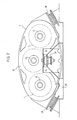
- the invention essentially consists in grouping several elongated cylindrical oleopneumatic accumulator elements of known type placed side by side inside a single envelope having substantially the length of the elements, a medium width and a low height, the high pressure accumulator elements being connected in parallel to constitute a single high pressure accumulator, while the interval between these and the envelope constitutes a low pressure accumulator, the high pressure accumulators being moreover suspended in the envelope by their mouth and their tail, while that the single casing joining the hydraulic connection end pieces is made up of a self-supporting assembly mounted on silent-blocks so that it can be easily installed on a horizontal surface of the vehicle, in particular on the roof of the latter, without requiring other transformations than the laying of junction pipes.
- the low pressure tank part can be in the open air or at low pressure without a membrane separation, and in particular the arrangement on the roof quite naturally makes it possible to supply the load-boosting pump with transmission-recovery.
- three prestressed high pressure accumulator elements 1 of the Leduc type are used, with an inner tubular bladder 2 surrounding a central tie rod 3 which goes from the hydraulic connection mouth 4 to the tail 5 provided with a plug. inflation and internal nitrogen pressure control.
- These three accumulators 1 have a large length, about 2 m, and a small diameter, and in accordance with the invention, they are placed side by side inside a single envelope 6 constituted by a ferrule 7 made of sheet steel, of substantially oval section, closed by two end flanges 8 and 9, for example made of cast aluminum, which are welded to the ferrule 7.
- the three accumulators are fixed by means of screws 10 on a single cover 11 fixing itself by means of screws 12 on the rear flange 9, this single cover 11 constituting at the same time the connection manifold in parallel of the three nozzles 4 by means of transverse conduits 13 towards the single high pressure connection nozzle 14.
- the tail 5 of each accumulator 1 is introduced sealingly in a nozzle 15 fixed on the front flange 8 and allowing access to the inflation and control nozzle not shown.
- the space 16 between the casing 7 and the three high pressure accumulators 1 constitutes the low pressure accumulator communicating with the low pressure connection end piece 17.
- the various high pressure accumulators 1 are thus rigidly fixed and suspended by their two ends in the casing 6, the latter constitutes a rigid self-supporting assembly which is also mounted on three silent blocks including two lateral 18 close to the rear flange 9, and an end 19 located in the center, in front of the front flange 8.
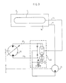
- the compact assembly thus formed can be fixed in one block at any location on the vehicle, but preferably on the roof 20 of the vehicle in the case of a bus or a panel van.
- the transformation of the vehicle is therefore limited to the laying of the two pipes starting from the end pieces 14 and 17 to join the hydrostatic devices of the recovery transmission.
- the low pressure pipe 17 supplies the booster pump 21 located at the lower level of the vehicle, so that the loading of this pipe, due to the position on the roof 20 of the vehicle, is particularly favorable.
- the high pressure line 14 is connected to a valve box 22 which provides the alternative connection with one or other of the inlet / outlet 23 and 24 of a hydraulic machine 25 for energy recovery-restitution connected to the transmission. .
- Such a valve box 22 may prove to be useless if, on the contrary, a machine with inversion of displacement (or "four dials") is used for the machine 25.
- hydraulic recovery-restitution machine 25 itself is replaced by other machines if one uses the arrangement described elsewhere in French patent application 82 08 855 (FR-A-2527288) in the name of the plaintiff.
- the low pressure tank 16 can be opened to the open air using a breather or even be kept under low pressure but without requiring air / oil separation membrane.
- any other type of high pressure accumulator 1 than the Leduc type taken as an example could be used, for example a non-prestressed accumulator with an internal bladder, the suspension continuing to be provided at the rear by the mouth and on the front side by any appropriate means, possibly by a bowl fixed on the front flange 8 on the inside and in which the body of the tank 1 is centered.
- this can have standard dimensions and capacity suitable for a large number of types of vehicles, but it is also possible to provide different capacity values by modifying only the length of the casing 7 as well as of the tanks 1, therefore without major modification of the standards and of the tools.
- Another adaptation of the capacity consists simply in deleting some of the accumulators 1 in order to modify the number thereof.
Landscapes
- Engineering & Computer Science (AREA)
- Mechanical Engineering (AREA)
- Chemical & Material Sciences (AREA)
- Combustion & Propulsion (AREA)
- Transportation (AREA)
- General Engineering & Computer Science (AREA)
- Supply Devices, Intensifiers, Converters, And Telemotors (AREA)
- Vehicle Body Suspensions (AREA)
Claims (4)
dass alle diese ölpneumatischen Speicher (1) jeweils mittels besagten Anschlusses am hydraulischen Ende (4) mit einem einzigen Glied (11) verbunden sind, das sowohl einen Kollektor (13) zur mechanischen und hydraulischen Parallelverbindung aller hydraulischen Enden (4) mit einem gemeinsamen Hochdruckein- und -auslassrohr (14) als auch einen Deckel zum Schliessen jener Öffnung in der Vorderplatte (9) des Gehäuses darstellt.
Applications Claiming Priority (2)
| Application Number | Priority Date | Filing Date | Title |
|---|---|---|---|
| FR8212517A FR2530209A1 (fr) | 1982-07-16 | 1982-07-16 | Reservoir d'energie oleopneumatique pour l'accumulation de l'energie de freinage recuperee sur un vehicule |
| FR8212517 | 1982-07-16 |
Publications (3)
| Publication Number | Publication Date |
|---|---|
| EP0099083A2 EP0099083A2 (de) | 1984-01-25 |
| EP0099083A3 EP0099083A3 (en) | 1984-02-29 |
| EP0099083B1 true EP0099083B1 (de) | 1987-11-19 |
Family
ID=9276052
Family Applications (1)
| Application Number | Title | Priority Date | Filing Date |
|---|---|---|---|
| EP83106727A Expired EP0099083B1 (de) | 1982-07-16 | 1983-07-08 | Ölpneumatischer Energiespeicher für Anhäufung der wiedererlangten Bremsenergie an einem Fahrzeug |
Country Status (5)
| Country | Link |
|---|---|
| US (1) | US4520840A (de) |
| EP (1) | EP0099083B1 (de) |
| DE (1) | DE3374538D1 (de) |
| ES (1) | ES524140A0 (de) |
| FR (1) | FR2530209A1 (de) |
Cited By (1)
| Publication number | Priority date | Publication date | Assignee | Title |
|---|---|---|---|---|
| DE4409086A1 (de) * | 1994-02-26 | 1995-11-16 | Kurt Huber | Energie-/Mengen-Speicher 2 |
Families Citing this family (38)
| Publication number | Priority date | Publication date | Assignee | Title |
|---|---|---|---|---|
| JPH0649447Y2 (ja) * | 1987-03-30 | 1994-12-14 | トヨタ自動車株式会社 | 車両のエアサスペンシヨン用回路 |
| US8079408B2 (en) * | 2003-09-22 | 2011-12-20 | Bosch Rexroth Corporation | Pressure vessel assembly for integrated pressurized fluid system |
| US6922997B1 (en) | 2004-02-03 | 2005-08-02 | International Truck Intellectual Property Company, Llc | Engine based kinetic energy recovery system for vehicles |
| US7363127B2 (en) * | 2004-06-07 | 2008-04-22 | International Truck Intellectual Property Company, Llc | Air brake system monitoring for pre-trip inspection |
| DE202006009223U1 (de) * | 2006-05-17 | 2007-09-27 | Liebherr-Werk Bischofshofen Ges.M.B.H. | Maschine, insbesondere Baumaschine |
| US8448433B2 (en) | 2008-04-09 | 2013-05-28 | Sustainx, Inc. | Systems and methods for energy storage and recovery using gas expansion and compression |
| US8677744B2 (en) | 2008-04-09 | 2014-03-25 | SustaioX, Inc. | Fluid circulation in energy storage and recovery systems |
| US8359856B2 (en) | 2008-04-09 | 2013-01-29 | Sustainx Inc. | Systems and methods for efficient pumping of high-pressure fluids for energy storage and recovery |
| US8225606B2 (en) | 2008-04-09 | 2012-07-24 | Sustainx, Inc. | Systems and methods for energy storage and recovery using rapid isothermal gas expansion and compression |
| US8250863B2 (en) | 2008-04-09 | 2012-08-28 | Sustainx, Inc. | Heat exchange with compressed gas in energy-storage systems |
| EP2280841A2 (de) | 2008-04-09 | 2011-02-09 | Sustainx, Inc. | Systeme und verfahren zur energiespeicherung und & 8209;rückgewinnung unter verwendung von druckgas |
| US8479505B2 (en) | 2008-04-09 | 2013-07-09 | Sustainx, Inc. | Systems and methods for reducing dead volume in compressed-gas energy storage systems |
| US8037678B2 (en) | 2009-09-11 | 2011-10-18 | Sustainx, Inc. | Energy storage and generation systems and methods using coupled cylinder assemblies |
| US7958731B2 (en) | 2009-01-20 | 2011-06-14 | Sustainx, Inc. | Systems and methods for combined thermal and compressed gas energy conversion systems |
| US8474255B2 (en) | 2008-04-09 | 2013-07-02 | Sustainx, Inc. | Forming liquid sprays in compressed-gas energy storage systems for effective heat exchange |
| US8240140B2 (en) | 2008-04-09 | 2012-08-14 | Sustainx, Inc. | High-efficiency energy-conversion based on fluid expansion and compression |
| US20100307156A1 (en) | 2009-06-04 | 2010-12-09 | Bollinger Benjamin R | Systems and Methods for Improving Drivetrain Efficiency for Compressed Gas Energy Storage and Recovery Systems |
| WO2009152141A2 (en) | 2008-06-09 | 2009-12-17 | Sustainx, Inc. | System and method for rapid isothermal gas expansion and compression for energy storage |
| US7963110B2 (en) | 2009-03-12 | 2011-06-21 | Sustainx, Inc. | Systems and methods for improving drivetrain efficiency for compressed gas energy storage |
| WO2010117853A1 (en) | 2009-04-06 | 2010-10-14 | Vanderbilt University | High energy density elastic accumulator and method of use thereof |
| US8104274B2 (en) | 2009-06-04 | 2012-01-31 | Sustainx, Inc. | Increased power in compressed-gas energy storage and recovery |
| RU2556947C2 (ru) * | 2009-10-05 | 2015-07-20 | Роберт Бош Гмбх | Система аккумулирования энергии, включающая в себя узел расширяемого аккумулятора и резервуара |
| WO2011056855A1 (en) | 2009-11-03 | 2011-05-12 | Sustainx, Inc. | Systems and methods for compressed-gas energy storage using coupled cylinder assemblies |
| US8191362B2 (en) | 2010-04-08 | 2012-06-05 | Sustainx, Inc. | Systems and methods for reducing dead volume in compressed-gas energy storage systems |
| US8171728B2 (en) | 2010-04-08 | 2012-05-08 | Sustainx, Inc. | High-efficiency liquid heat exchange in compressed-gas energy storage systems |
| US8234863B2 (en) | 2010-05-14 | 2012-08-07 | Sustainx, Inc. | Forming liquid sprays in compressed-gas energy storage systems for effective heat exchange |
| US8495872B2 (en) | 2010-08-20 | 2013-07-30 | Sustainx, Inc. | Energy storage and recovery utilizing low-pressure thermal conditioning for heat exchange with high-pressure gas |
| US8578708B2 (en) | 2010-11-30 | 2013-11-12 | Sustainx, Inc. | Fluid-flow control in energy storage and recovery systems |
| EP2670985A4 (de) * | 2011-01-31 | 2017-03-08 | Vanderbilt University | Elastisches hydraulisches speicher-/behältersystem |
| US8434524B2 (en) | 2011-01-31 | 2013-05-07 | Vanderbilt University | Elastic hydraulic accumulator/reservoir system |
| CA2826350A1 (en) | 2011-02-03 | 2012-08-09 | Vanderbilt University | Multiple accumulator systems and methods of use thereof |
| US20120273076A1 (en) * | 2011-04-28 | 2012-11-01 | Robert Bosch Gmbh | Compact hydraulic accumulator |
| JP2014522460A (ja) | 2011-05-17 | 2014-09-04 | サステインエックス, インコーポレイテッド | 圧縮空気エネルギー貯蔵システムにおける効率的二相熱移送のためのシステムおよび方法 |
| US20130091836A1 (en) | 2011-10-14 | 2013-04-18 | Sustainx, Inc. | Dead-volume management in compressed-gas energy storage and recovery systems |
| US9249847B2 (en) | 2011-12-16 | 2016-02-02 | Vanderbilt University | Distributed piston elastomeric accumulator |
| FR3000704B1 (fr) * | 2013-01-07 | 2015-02-13 | Technoboost | Module hydraulique comportant des accumulateurs haute et basse pression, pour un vehicule hybride |
| US9127811B2 (en) | 2013-06-05 | 2015-09-08 | Louis P. Vickio, Jr. | Hydraulic accumulator |
| EP3267046A1 (de) | 2016-07-07 | 2018-01-10 | DANA ITALIA S.r.l. | System zur rückgewinnung von energie aus einem hydraulischen aktuator |
Family Cites Families (14)
| Publication number | Priority date | Publication date | Assignee | Title |
|---|---|---|---|---|
| US339885A (en) * | 1886-04-13 | Mode of re-enforcing tubular or hollow structures | ||
| US194217A (en) * | 1877-08-14 | Improvement in reservoirs for compressed air | ||
| US846266A (en) * | 1905-11-22 | 1907-03-05 | Bethlehem Steel Corp | Multiple-pressure system. |
| US1692670A (en) * | 1924-12-30 | 1928-11-20 | Mesurier Louis John Le | Apparatus for storing fluid under pressure |
| US1891644A (en) * | 1931-02-12 | 1932-12-20 | Westinghouse Air Brake Co | Reservcir construction |
| US2331921A (en) * | 1938-05-31 | 1943-10-19 | Mercier Jean | Storage device |
| FR2188574A5 (de) * | 1972-06-06 | 1974-01-18 | Westinghouse Freins & Signaux | |
| US4062356A (en) * | 1974-12-04 | 1977-12-13 | U.S. Divers Co. | Underwater diving system |
| IL46964A (en) * | 1975-03-30 | 1977-06-30 | Technion Res & Dev Foundation | Hydrostatic relay system |
| DE2515048C3 (de) * | 1975-04-07 | 1982-02-18 | M.A.N. Maschinenfabrik Augsburg-Nuernberg Ag, 8000 Muenchen | Antriebsanordnung mit Energiespeicher, insbesondere für Straßenfahrzeuge |
| FR2323067A1 (fr) * | 1975-09-08 | 1977-04-01 | Carman Vincent | Circuit hydraulique de freinage et d'acceleration pour vehicule |
| FR2425609A1 (fr) * | 1978-05-12 | 1979-12-07 | Cytec France | Dispositif de stockage d'energie dans une enceinte a plusieurs enveloppes elastiques. |
| DE3031232A1 (de) * | 1980-08-19 | 1982-03-25 | Dipl.-Phys. Dr. Hugo 4750 Unna Balster | Verfahren und vorrichtung zum uebertragen und/oder speichern von rotationsenergie |
| US4441573A (en) * | 1980-09-04 | 1984-04-10 | Advanced Energy Systems Inc. | Fuel-efficient energy storage automotive drive system |
-
1982
- 1982-07-16 FR FR8212517A patent/FR2530209A1/fr active Granted
-
1983
- 1983-07-08 EP EP83106727A patent/EP0099083B1/de not_active Expired
- 1983-07-08 DE DE8383106727T patent/DE3374538D1/de not_active Expired
- 1983-07-12 US US06/513,138 patent/US4520840A/en not_active Expired - Lifetime
- 1983-07-15 ES ES524140A patent/ES524140A0/es active Granted
Cited By (1)
| Publication number | Priority date | Publication date | Assignee | Title |
|---|---|---|---|---|
| DE4409086A1 (de) * | 1994-02-26 | 1995-11-16 | Kurt Huber | Energie-/Mengen-Speicher 2 |
Also Published As
| Publication number | Publication date |
|---|---|
| FR2530209A1 (fr) | 1984-01-20 |
| EP0099083A2 (de) | 1984-01-25 |
| ES8404259A1 (es) | 1984-04-16 |
| EP0099083A3 (en) | 1984-02-29 |
| FR2530209B1 (de) | 1985-01-11 |
| ES524140A0 (es) | 1984-04-16 |
| US4520840A (en) | 1985-06-04 |
| DE3374538D1 (en) | 1987-12-23 |
Similar Documents
| Publication | Publication Date | Title |
|---|---|---|
| EP0099083B1 (de) | Ölpneumatischer Energiespeicher für Anhäufung der wiedererlangten Bremsenergie an einem Fahrzeug | |
| EP2904304B1 (de) | Wasserstoffspeichertank mit durch vereinfachte herstellung hergestellten metallhydriden sowie lagerungsvorrichtung mit mindestens solch einem tank | |
| WO2011058053A1 (fr) | Reservoir de stockage d'hydrogene a hydrures metalliques | |
| WO2011058044A1 (fr) | Reservoir de stockage d'hydrogene a hydrures metalliques | |
| FR2468015A1 (fr) | Reservoir a utiliser avec un maitre cylindre en tandem | |
| WO2010052422A2 (fr) | Procédé de montage d'une tour d'exploitation d'un fluide dans une étendue d'eau et tour d'exploitation associée | |
| EP1554476A1 (de) | Vorrichtung und verfahren zum entgasen an kraftfahrzeugen | |
| EP4474187A1 (de) | Energiespeichervorrichtung | |
| EP3259404B1 (de) | Schwerkraftbasierte struktur zur abstützung und verankerung einer offshore-windturbine und verfahren zum schleppen und installieren davon im meer | |
| FR2938002A1 (fr) | Procede de mise en place d'une tour d'exploitation d'un fluide dans une etendue d'eau avec un engin de traction | |
| FR2978215A1 (fr) | Circuit hydraulique ferme comprenant une partie haute pression et une partie basse pression avec un moyen de maintien de la basse pression | |
| FR2946007A1 (fr) | Systeme de recuperation et de traction d'un objet immerge, notamment une mine aquatique. | |
| FR2698050A1 (fr) | Système de sécurité pour véhicule routier fonctionnant au combustible gazeux. | |
| JPS63239320A (ja) | 水中エネルギ貯蔵装置 | |
| WO2018138141A1 (fr) | Systeme moteur aero-hydraulique | |
| FR2783034A1 (fr) | Reservoir destine a contenir du fluide sous pression comportant des renforts internes | |
| EP0494019B1 (de) | Hydraulische, stösselbetätigte Abwurfvorrichtung mit automatischer Nachladung | |
| WO2016132056A1 (fr) | Structure de support et d'ancrage d'eolienne maritime du type tour treillis et procede de remorquage et depose en mer | |
| FR2616464A1 (fr) | Caisson pour constructions hydrotechniques | |
| EP0360697B1 (de) | Pumpenanlage, insbesondere für Bewässerung | |
| EP2686182A1 (de) | Hydraulisches antriebssystem für kraftfahrzeuge | |
| FR2831204A1 (fr) | Dispositif de guidage dans une installation de forage en mer et procede de realisation | |
| FR3101847A1 (fr) | Ballast pour engin sous-marin et engin sous-marin comprenant au moins un tel ballast | |
| EP2941360B1 (de) | Hydraulikmodul mit hoch- und niederdruckakkumulatoren für ein hybridfahrzeug | |
| EP1466091A1 (de) | Vorrichtung zur verwendung von wellenenergie |
Legal Events
| Date | Code | Title | Description |
|---|---|---|---|
| PUAI | Public reference made under article 153(3) epc to a published international application that has entered the european phase |
Free format text: ORIGINAL CODE: 0009012 |
|
| PUAL | Search report despatched |
Free format text: ORIGINAL CODE: 0009013 |
|
| AK | Designated contracting states |
Designated state(s): BE DE GB IT SE |
|
| AK | Designated contracting states |
Designated state(s): BE DE GB IT SE |
|
| 17P | Request for examination filed |
Effective date: 19840425 |
|
| ITF | It: translation for a ep patent filed | ||
| GRAA | (expected) grant |
Free format text: ORIGINAL CODE: 0009210 |
|
| AK | Designated contracting states |
Kind code of ref document: B1 Designated state(s): BE DE GB IT SE |
|
| REF | Corresponds to: |
Ref document number: 3374538 Country of ref document: DE Date of ref document: 19871223 |
|
| GBT | Gb: translation of ep patent filed (gb section 77(6)(a)/1977) | ||
| PLBE | No opposition filed within time limit |
Free format text: ORIGINAL CODE: 0009261 |
|
| STAA | Information on the status of an ep patent application or granted ep patent |
Free format text: STATUS: NO OPPOSITION FILED WITHIN TIME LIMIT |
|
| 26N | No opposition filed | ||
| ITTA | It: last paid annual fee | ||
| EAL | Se: european patent in force in sweden |
Ref document number: 83106727.7 |
|
| PGFP | Annual fee paid to national office [announced via postgrant information from national office to epo] |
Ref country code: GB Payment date: 20010614 Year of fee payment: 19 |
|
| PGFP | Annual fee paid to national office [announced via postgrant information from national office to epo] |
Ref country code: SE Payment date: 20010702 Year of fee payment: 19 |
|
| PGFP | Annual fee paid to national office [announced via postgrant information from national office to epo] |
Ref country code: DE Payment date: 20010713 Year of fee payment: 19 Ref country code: BE Payment date: 20010713 Year of fee payment: 19 |
|
| REG | Reference to a national code |
Ref country code: GB Ref legal event code: IF02 |
|
| PG25 | Lapsed in a contracting state [announced via postgrant information from national office to epo] |
Ref country code: GB Free format text: LAPSE BECAUSE OF NON-PAYMENT OF DUE FEES Effective date: 20020708 |
|
| PG25 | Lapsed in a contracting state [announced via postgrant information from national office to epo] |
Ref country code: SE Free format text: LAPSE BECAUSE OF NON-PAYMENT OF DUE FEES Effective date: 20020709 |
|
| PG25 | Lapsed in a contracting state [announced via postgrant information from national office to epo] |
Ref country code: BE Free format text: LAPSE BECAUSE OF NON-PAYMENT OF DUE FEES Effective date: 20020731 |
|
| BERE | Be: lapsed |
Owner name: *RENAULT VEHICULES INDUSTRIELS Effective date: 20020731 |
|
| PG25 | Lapsed in a contracting state [announced via postgrant information from national office to epo] |
Ref country code: DE Free format text: LAPSE BECAUSE OF NON-PAYMENT OF DUE FEES Effective date: 20030201 |
|
| GBPC | Gb: european patent ceased through non-payment of renewal fee |
Effective date: 20020708 |
|
| EUG | Se: european patent has lapsed |