EP0099088A2 - Spritzgiessnadelverschlussbuchse und ihr Herstellungsverfahren - Google Patents
Spritzgiessnadelverschlussbuchse und ihr Herstellungsverfahren Download PDFInfo
- Publication number
- EP0099088A2 EP0099088A2 EP83106739A EP83106739A EP0099088A2 EP 0099088 A2 EP0099088 A2 EP 0099088A2 EP 83106739 A EP83106739 A EP 83106739A EP 83106739 A EP83106739 A EP 83106739A EP 0099088 A2 EP0099088 A2 EP 0099088A2
- Authority
- EP
- European Patent Office
- Prior art keywords
- valve pin
- main body
- body portion
- bore
- pin bushing
- Prior art date
- Legal status (The legal status is an assumption and is not a legal conclusion. Google has not performed a legal analysis and makes no representation as to the accuracy of the status listed.)
- Granted
Links
Images


Classifications
-
- B—PERFORMING OPERATIONS; TRANSPORTING
- B23—MACHINE TOOLS; METAL-WORKING NOT OTHERWISE PROVIDED FOR
- B23P—METAL-WORKING NOT OTHERWISE PROVIDED FOR; COMBINED OPERATIONS; UNIVERSAL MACHINE TOOLS
- B23P15/00—Making specific metal objects by operations not covered by a single other subclass or a group in this subclass
- B23P15/007—Making specific metal objects by operations not covered by a single other subclass or a group in this subclass injection moulding tools
-
- B—PERFORMING OPERATIONS; TRANSPORTING
- B29—WORKING OF PLASTICS; WORKING OF SUBSTANCES IN A PLASTIC STATE IN GENERAL
- B29C—SHAPING OR JOINING OF PLASTICS; SHAPING OF MATERIAL IN A PLASTIC STATE, NOT OTHERWISE PROVIDED FOR; AFTER-TREATMENT OF THE SHAPED PRODUCTS, e.g. REPAIRING
- B29C45/00—Injection moulding, i.e. forcing the required volume of moulding material through a nozzle into a closed mould; Apparatus therefor
- B29C45/17—Component parts, details or accessories; Auxiliary operations
- B29C45/26—Moulds
- B29C45/27—Sprue channels ; Runner channels or runner nozzles
- B29C45/28—Closure devices therefor
- B29C45/2806—Closure devices therefor consisting of needle valve systems
-
- B—PERFORMING OPERATIONS; TRANSPORTING
- B29—WORKING OF PLASTICS; WORKING OF SUBSTANCES IN A PLASTIC STATE IN GENERAL
- B29C—SHAPING OR JOINING OF PLASTICS; SHAPING OF MATERIAL IN A PLASTIC STATE, NOT OTHERWISE PROVIDED FOR; AFTER-TREATMENT OF THE SHAPED PRODUCTS, e.g. REPAIRING
- B29C45/00—Injection moulding, i.e. forcing the required volume of moulding material through a nozzle into a closed mould; Apparatus therefor
- B29C45/17—Component parts, details or accessories; Auxiliary operations
- B29C45/26—Moulds
- B29C45/27—Sprue channels ; Runner channels or runner nozzles
- B29C45/28—Closure devices therefor
- B29C45/2806—Closure devices therefor consisting of needle valve systems
- B29C2045/2889—Sealing guide bushings therefor
Definitions
- This invention relates to a valve gated injection molding system and more particularly to a valve pin bushing for use in such a system.
- valve pin extends through the heated nozzle from the actuating mechanism to the gate.
- the hot manifold plate extends between the cooled back plate supporting the actuating mechanism and the cooled cavity plate in which the heated nozzle is seated. Therefore, in order to avoid alignment problems between the valve pin, the actuating mechanism and the gate due to lateral thermal expansion of the manifold plate, it is necessary that ample clearance be provided between the valve pin and the manifold plate.
- valve pin bushing which is located against the heater nozzle to provide a seal against leakage of the pressurized melt and which may improve the lateral location of the heated nozzle in the cavity plate.
- the invention provides a valve gated injection molding system having a heated nozzle seated in a well in a cooled cavity plate, a gate in the cavity plate leading to a cavity, the heated nozzle having a bore extending therethrough from a first surface into alignment with the gate, an elongated valve pin which reciprocates in the bore in the heated nozzle, actuating mechanism for driving the valve pin between open and closed positions, a melt passage which extends through a manifold plate and around the valve pin in the bore in the heated nozzle to convey pressurized melt from a molding machine to the gate, the improvement further comprising a valve pin bushing having a main body portion located between the manifold plate and the heated nozzle, the main body portion having first and second opposed surfaces and an outer periphery, a portion of the first surface abutting against the manifold plate and at least a portion of the second surface abutting against the first surface of the heated nozzle, the main body portion of the valve pin bushing having a
- the invention further provides a method of manufacturing an injection molding valve pin bushing having a main body portion and an integral collar portion., the main body portion having first and second opposed surfaces and an outer peripheral locating flange, the collar portion joining the main body portion at said first surface, the collar portion and the main body portion having a valve pin bore with an inner wall with a generally cylindrical shape extending therethrough, the valve pin bore having an enlarged portion extending to said second surface, the main body portion having a melt duct extending from the first surface to join the enlarged portion of the valve pin bore, the inner wall of the valve pin bore being interrupted by a circumferential opening which is vented to atmosphere through a vent duct, the circumferential opening being located in the collar portion adjacent the main body portion with the vent duct located in the main body portion, comprising the steps of machining the collar portion with a well in a first end thereof to form the circumferential opening, machining the main body portion to provide first and second opposed surfaces and an outer peripheral locating flange to predetermined dimensions, drilling
- Figure 1 shows a portion of a multi-cavity valve gated injection molding system.
- the portion of the system shown has a heated nozzle 10 seated in a well 12 in a cavity plate 14 with an elongated valve pin.l6 driven by hydraulic actuating machanism 18 located in back plate 20.
- the heated nozzle 10 has a helical electric heating element 22 which extends. around a central bore 24 through which the valve pin l6 extends.
- the tip end 26 of the valve pin 16 extends through a hollow nozzle seal 28 seated in the heated nozzle 10 into a gate 30 leading to the cavity 32.
- a melt passage 34 extends from a recessed inlet 36 where it receives pressurized melt from a molding machine (not shown) to a manifold plate 38 in which it branches outward.
- the manifold plate 38 is centrally laterally located relative to the cavity plate by locating ring 40 and has several outwardly extending arms, each with one of the branches of the melt passage.
- the melt passage 34 extends from the manifold plate 38, through the valve pin bushing 42 and through the bore 24 of the heated nozzle 10 around the valve pin 16.
- Each valve pin bushing 42 has a main body portion 44 and an integral collar portion 46 which extends into an opening 47 in the manifold plate 38.
- the valve pin bushing 42 is securely fixed to the heated nozzle 10 by bolts 48 and a portion of the main body portion 44 extends between the manifold plate 38 and the heated nozzle 10.
- the main body portion 44 has a first flat surface 50, a portion of which abuts against the manifold plate 38 and a second flat surface 52 which abuts against a first flat surface 54 of the heated nozzle 10.
- the outer periphery 51 of the main body portion 44 of the valve pin bushing has a locating flange 56 which extends into contact with the side 58 of the well 12 to accurately laterally locate the valve pin bushing 42.
- the valve pin bushing 42 also has a central bore 60 which extends through both the collar portion 46 and the main body portion 44.
- the valve pin 16 extends through the bore 60 of the valve pin bushing 42 which has an inner wall 62 with a generally cylindrical shape.
- the bore 60 has an enlarged portion 64 leading to the second surface 52 of the main body portion 44, it does have a portion which snugly receives the valve pin 16 over a sufficient ratio of length to diameter to provide an effective seal against leakage of the pressurized melt around the valve pin 16.
- the inner wall 62 of the bore 60 is interrupted by a circumferential opening 66 which is vented to atmosphere through a vent duct 68.
- the main body portion 44 has a melt duct 70 which extends diagonally from the first surface 50 to join the enlarged portion 64 of the valve pin bushing bore 60 to form a portion of the melt passage 34 which conveys the melt to the cavity 32.
- the melt be kept hot within a predetermined temperature range as it flows all the way along the melt passage 34.
- the nozzle 10 is heated by the heating element 22 which is cast in highly conductive copper.
- the steel manifold plate 38 is heated by heating devices not shown and the valve pin bushing 42 which is also formed of high speed steel is heated by the hot melt flowing through them as well as by contact with the heated manifold plate and nozzle.
- the surrounding cavity plate.14 and the back plate 20 which holds the actuating mechanism 18 are cooled-in a conventional manner by cooling channels 72.
- an insulative air space or gap 74 is provided between the hot and cool components.
- the valve pin actuating mechanism 18 has a hydraulically driven piston 78 which reciprocates in a cylinder 80.
- the valve pin 16 extends through a central hole 82 in the piston 78 and its enlarged head 84 is secured to the piston 78 by a plug 86 which is screwed tightly down on top of it.
- the cylinder 80 is seated in the back plate 20 so that the valve pin 16 is in alignment with the bores through the valve pin bushing 42 and the heated nozzle 10.
- the piston 78 and the valve pin 16 are driven between open and closed positions by a controlled source of pressurized hydraulic fluid (not shown) which is connected to opposite sides of the piston 78 by hydraulic fluid ducts 88.
- manifold plated 38 heats up to operating temperature, it expands radially outward due to it being centrally located relative to the cavity plate 14 by locating ring 40. This thermal expansion causes each arm of the manifold plate 38 to slide across the first surface 50 of the main body portion 44 of the respective valve pin bushing 42 which is located in the cooled cavity plate 14.
- the system is designed so that the ducts move into alignment to provide the continuous melt passage 34 at the predetermined operating temperature.
- each heated nozzle 10 is accurately located in the well 12 in the cavity plate 14 by the locating bushing portion 76 which is seated on shoulder 94 and the valve pin bushing 42 is attached to the heated nozzle 10 by bolts 48, there is still a tendency for the heated nozzle 10 to tip or cock as a result of the frictional forces from the thermal expansion of the manifold plate 38. This is offset by the provision of the locating flange 56 around the valve pin bushing which abuts against the cavity plate 14 to act as an independent lateral locator for the unit.
- valve pin 16 As the valve pin 16 reciprocates, there may be a slight seepage of the pressurized melt from the melt passage into the valve pin bushing bore 60 around the valve pin 16. Depending upon the material, this melt may be trapped which could result in the breakdown or decomposition of the plasticizers. This is due to the shearing action from the reciprocating motion of the valve pin on the material trapped in this confined space. This results in the formation of hot pressurized gases and acids which attack the surface of the valve pin and the wall of the bushing seal. The resulting corrosion, wear and build up of solidified material could result in seizure of the valve pin, thereby shortening the operating life of the mechanism.
- circumferential opening 66 and vent passage 68 relieves the pressure on the material, allows harmful gases to escape and permits the material trapped between the valve stem and the wall of the bushing seal to remain partially fluid.
- the provision of this circumferential opening and vent have been found to substantially extend the operative life span of the mechanism.
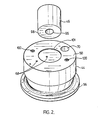
- the main body portion 44 and the collar portion 46 are first machined and drilled as seen in Figure 2.
- the collar portion 46 has a cylindrical well 96 drilled in one end 98 to form the circumferential opening 66.
- the main body portion 44 is machined to have the first and second flat surfaces 50,52 and the outer peripheral locating flange 56. It is drilled to form the diagonally extending melt duct 70 and counter-bored bolt holes 100, as well as a central locating recess 101. Intersecting holes are drilled at predetermined locations in the first surface 50 of the main body portion 44 to form the vent duct 68.
- the collar portion 46 is then positioned into recess 101 on top of the main body portion 44 in a position in which the vent duct 68 extends through the main body portion to connect to the cylindrical well 96 in the collar portion 46 near its inner wall 62.
- a nickel brazing paste is applied to the interface between them and a batch of assembled units are heated in a vacuum furnace 102 as shown in Figure 3.
- the temperature and heating time must be sufficient to first melt the paste causing it to run all around the joint or interface and then braze the two portions together.
- brazing in a vacuum furnace provides an improved bond between the two portions which provides the valve pin bushing 42 as a strong integral unit.
- the valve pin bushing 42 is drilled centrally through the well 96 to form the bore 60 with the circumferential opening 66 around it.
- the bore 60 has an aligned enlarged portion 64 which is drilled from the second surface 52 and intersects the diagonal melt duct 68.
- valve pin bushing 42 While the description of the valve pin bushing 42 and the method of making it have been given with respect to preferred embodiments, it is not to be construed in a limiting sense. Variations and modifications will occur to those skilled in the art. For instance, it is apparent that the valve pin bushing 42 may have structure other than the flange 56 to laterally locate it. Similarly, the vent duct 68 need not be exactly as shown, and the dimensions of the collar portion 46 and the main body portion 44 will depend upon the particular application and the ratio of valve pin bore 60 length to diameter required to provide the necessary seal. The melt duct 70 need not join the enlarged portion 64 of the bore in precisely the location shown and, in fact, they could join in the heated nozzle 10 itself, although this would be a less satisfactory arrangement. Reference is made to the appended claims for a definition of the invention.
Landscapes
- Engineering & Computer Science (AREA)
- Mechanical Engineering (AREA)
- Manufacturing & Machinery (AREA)
- Moulds For Moulding Plastics Or The Like (AREA)
- Injection Moulding Of Plastics Or The Like (AREA)
- Pens And Brushes (AREA)
- Brushes (AREA)
Priority Applications (1)
| Application Number | Priority Date | Filing Date | Title |
|---|---|---|---|
| AT83106739T ATE31159T1 (de) | 1982-07-12 | 1983-07-08 | Spritzgiessnadelverschlussbuchse und ihr herstellungsverfahren. |
Applications Claiming Priority (2)
| Application Number | Priority Date | Filing Date | Title |
|---|---|---|---|
| CA407095 | 1982-07-12 | ||
| CA000407095A CA1190018A (en) | 1982-07-12 | 1982-07-12 | Injection molding valve pin bushing and method |
Publications (3)
| Publication Number | Publication Date |
|---|---|
| EP0099088A2 true EP0099088A2 (de) | 1984-01-25 |
| EP0099088A3 EP0099088A3 (en) | 1984-07-04 |
| EP0099088B1 EP0099088B1 (de) | 1987-12-02 |
Family
ID=4123201
Family Applications (1)
| Application Number | Title | Priority Date | Filing Date |
|---|---|---|---|
| EP83106739A Expired EP0099088B1 (de) | 1982-07-12 | 1983-07-08 | Spritzgiessnadelverschlussbuchse und ihr Herstellungsverfahren |
Country Status (6)
| Country | Link |
|---|---|
| US (1) | US4433969A (de) |
| EP (1) | EP0099088B1 (de) |
| JP (1) | JPS5931129A (de) |
| AT (1) | ATE31159T1 (de) |
| CA (1) | CA1190018A (de) |
| DE (1) | DE3374766D1 (de) |
Cited By (11)
| Publication number | Priority date | Publication date | Assignee | Title |
|---|---|---|---|---|
| EP0163083A3 (en) * | 1984-05-29 | 1988-01-13 | Mold-Masters Limited | Injection molding peripheral opening core ring gate |
| EP0264723A3 (de) * | 1986-10-15 | 1989-07-19 | Mold-Masters Limited | Abdichtungs- und Haltehülse zum Spritzgiessen |
| EP0264725A3 (en) * | 1986-10-23 | 1989-08-23 | Mold-Masters Limited | Dual feed bushing for multi-cavity injection molding |
| EP0373293A3 (de) * | 1988-12-16 | 1991-06-12 | Jobst Ulrich Gellert | Zahnstangenbetätigungsmechanismus für Spritzgiessventilnadel |
| EP0590678A1 (de) * | 1992-09-30 | 1994-04-06 | Husky Injection Molding Systems Ltd. | Buchse für Heisskanalverteiler |
| EP0668141A1 (de) * | 1994-02-14 | 1995-08-23 | Jobst Ulrich Gellert | Abdichtungsbüchse für Ventil im Spritzgiessen mit dünnem Kragenteil |
| EP0732185A1 (de) * | 1995-03-02 | 1996-09-18 | Husky Injection Molding Systems Ltd. | Verbesserte Düse-Sammelanschlussplatte für eine Spritzgussmaschine |
| WO2002032646A1 (fr) * | 2000-10-20 | 2002-04-25 | Delachaux S.A. | Dispositif d'injection auto-etancheifie pour une matiere thermoplastique |
| US6870441B2 (en) | 2000-10-24 | 2005-03-22 | France Telecom | Method for transforming bandpass filters to facilitate their production and resulting devices |
| CN103282181A (zh) * | 2011-01-04 | 2013-09-04 | 赫斯基注塑系统有限公司 | 具有歧管延伸件和偏置组件的模具工具系统 |
| CN118809201A (zh) * | 2024-09-02 | 2024-10-22 | 无锡市美峰橡胶制品制造有限公司 | 一种放风阀组件加工成型装置及其方法 |
Families Citing this family (35)
| Publication number | Priority date | Publication date | Assignee | Title |
|---|---|---|---|---|
| CA1193818A (en) * | 1983-03-24 | 1985-09-24 | Jobst U. Gellert | Hydraulically actuated injection molding system with alternate hydraulic connections |
| CA1230457A (en) * | 1984-05-25 | 1987-12-22 | Gellert, Jobst Ulrich | Injection molding nozzle probe and stack molding apparatus |
| CA1230473A (en) * | 1985-11-21 | 1987-12-22 | Arthur Harrison | Method of manufacturing injection molding manifold with plugs |
| CA1238161A (en) * | 1985-12-02 | 1988-06-21 | Jobst U. Gellert | Manufacturing method for selected gate configuration injection molding nozzles |
| US4913912A (en) * | 1986-09-29 | 1990-04-03 | Fast Heat Element Manufacturing Co., Inc. | Plastic injection mold apparatus with multiple tip torpedo heater |
| JPH0347853Y2 (de) * | 1986-01-24 | 1991-10-14 | ||
| US4919606A (en) * | 1988-12-21 | 1990-04-24 | Gellert Jobst U | Injection molding rack and pinion valve pin actuating mechanism |
| CA1274369A (en) * | 1989-02-28 | 1990-09-25 | Jobst Ulrich Gellert | Injection molding nozzle with self-supporting actuating mechanism |
| US5055028A (en) * | 1989-04-07 | 1991-10-08 | Panos Trakas | Internally heated torpedo with internal melt distribution chamber |
| CA1278409C (en) * | 1989-06-30 | 1991-01-02 | Jobst Ulrich Gellert | Injection molding system having dual feed bushing seated in manifold |
| US5147663A (en) * | 1990-10-09 | 1992-09-15 | Panos Trakas | Modular manifold assembly |
| JP2854459B2 (ja) * | 1992-05-11 | 1999-02-03 | 伊三五 美浦 | 射出成形等における可塑化流動体の間歇的加熱装置 |
| CA2219260C (en) * | 1997-10-23 | 2006-12-05 | Mold-Masters Limited | Injection molding apparatus having inter-manifold melt transfer bushings |
| US6261084B1 (en) * | 1998-08-28 | 2001-07-17 | Synventive Moldings Solutions Canada, Inc. | Elastically deformable nozzle for injection molding |
| US6655945B1 (en) | 1999-03-18 | 2003-12-02 | Mold Masters Limited | Apparatus and method for multi-layer injection molding |
| US6440350B1 (en) | 1999-03-18 | 2002-08-27 | Mold-Masters Limited | Apparatus and method for multi-layer injection molding |
| US6398537B2 (en) | 1999-04-02 | 2002-06-04 | Mold-Masters Limited | Shuttle system for an apparatus for injection molding |
| US6196826B1 (en) | 1999-05-28 | 2001-03-06 | Mold-Masters Limited | Seepage system for an injection molding apparatus |
| CA2273517C (en) | 1999-06-01 | 2008-04-01 | Jobst Ulrich Gellert | Injection molding heater with melt bore therethrough |
| US6679697B2 (en) | 2000-12-08 | 2004-01-20 | Husky Injection Molding Systems Ltd. | Flow detector apparatus |
| US6524093B2 (en) | 2000-12-08 | 2003-02-25 | Husky Injection Molding Systems, Ltd. | Flow deflector in an injection molding system |
| JP4026048B2 (ja) * | 2002-01-10 | 2007-12-26 | 株式会社ワコム | 可変インピーダンス・レファレンス回路及び方法 |
| US6890473B2 (en) * | 2002-09-03 | 2005-05-10 | Mold-Masters Limited | Alignment collar for a nozzle |
| US7189071B2 (en) * | 2003-02-12 | 2007-03-13 | Mold-Masters Limited | Telescopic manifold nozzle seal |
| DE602004013661D1 (de) * | 2003-03-21 | 2008-06-26 | Mold Masters 2007 Ltd | Spritzgiessnadelverschlussbuchse |
| US20040258795A1 (en) * | 2003-06-23 | 2004-12-23 | Hans Guenther | Injection molding nozzle with separate nozzle flange |
| DE102005049605A1 (de) * | 2004-10-19 | 2006-04-20 | Mold-Masters Ltd., Georgetown | Verteilereinsatz für eine Spritzgießvorrichtung |
| US7381050B2 (en) | 2004-10-20 | 2008-06-03 | Mold-Masters (2007) Limited | Snap on flange for injection molding nozzle |
| US7407380B2 (en) * | 2005-02-04 | 2008-08-05 | Mold-Masters (2007) Limited | Valve pin bushing with vent channels for an injection molding apparatus |
| US7890896B2 (en) * | 2005-11-18 | 2011-02-15 | Synopsys, Inc. | Method and apparatus for distinguishing combinational designs |
| CA2567936C (en) | 2006-11-14 | 2016-01-05 | Atomic Energy Of Canada Limited | Device and method for surface replication |
| WO2013122789A1 (en) * | 2012-02-16 | 2013-08-22 | Husky Injection Molding Systems Ltd. | Mold-tool system including pin-guidance mechansim |
| ES2951958T3 (es) | 2019-10-08 | 2023-10-26 | Milacron Llc | Aparato de moldeo por inyección con un puente térmico |
| DE102023106071A1 (de) * | 2023-03-10 | 2024-09-12 | Mht Mold & Hotrunner Technology Ag | Spritzgießmaschine mit Trennelement und Entlastungskanal |
| EP4450250A1 (de) * | 2023-04-19 | 2024-10-23 | Inglass S.p.A. | Injektorkörper zum spritzgiessen und zugehörige montageanordnung |
Family Cites Families (4)
| Publication number | Priority date | Publication date | Assignee | Title |
|---|---|---|---|---|
| US3806295A (en) * | 1970-11-04 | 1974-04-23 | J Gellert | Valve gate pin actuating mechanism |
| CA1029162A (en) | 1975-04-10 | 1978-04-11 | Jobst U. Gellert | Bushing seal for valve-gated injection mold |
| CA1136815A (en) * | 1980-07-15 | 1982-12-07 | Jobst U. Gellert | Injection molding nozzle seal |
| CA1174820A (en) | 1982-02-24 | 1984-09-25 | William J. Wiles | Injection molding valve pin direct pneumatic actuator |
-
1982
- 1982-07-12 CA CA000407095A patent/CA1190018A/en not_active Expired
- 1982-07-19 US US06/399,770 patent/US4433969A/en not_active Expired - Fee Related
-
1983
- 1983-07-08 DE DE8383106739T patent/DE3374766D1/de not_active Expired
- 1983-07-08 AT AT83106739T patent/ATE31159T1/de not_active IP Right Cessation
- 1983-07-08 EP EP83106739A patent/EP0099088B1/de not_active Expired
- 1983-07-11 JP JP58124897A patent/JPS5931129A/ja active Pending
Cited By (14)
| Publication number | Priority date | Publication date | Assignee | Title |
|---|---|---|---|---|
| EP0163083A3 (en) * | 1984-05-29 | 1988-01-13 | Mold-Masters Limited | Injection molding peripheral opening core ring gate |
| EP0264723A3 (de) * | 1986-10-15 | 1989-07-19 | Mold-Masters Limited | Abdichtungs- und Haltehülse zum Spritzgiessen |
| EP0264725A3 (en) * | 1986-10-23 | 1989-08-23 | Mold-Masters Limited | Dual feed bushing for multi-cavity injection molding |
| EP0373293A3 (de) * | 1988-12-16 | 1991-06-12 | Jobst Ulrich Gellert | Zahnstangenbetätigungsmechanismus für Spritzgiessventilnadel |
| EP0590678A1 (de) * | 1992-09-30 | 1994-04-06 | Husky Injection Molding Systems Ltd. | Buchse für Heisskanalverteiler |
| EP0668141A1 (de) * | 1994-02-14 | 1995-08-23 | Jobst Ulrich Gellert | Abdichtungsbüchse für Ventil im Spritzgiessen mit dünnem Kragenteil |
| EP0732185A1 (de) * | 1995-03-02 | 1996-09-18 | Husky Injection Molding Systems Ltd. | Verbesserte Düse-Sammelanschlussplatte für eine Spritzgussmaschine |
| WO2002032646A1 (fr) * | 2000-10-20 | 2002-04-25 | Delachaux S.A. | Dispositif d'injection auto-etancheifie pour une matiere thermoplastique |
| FR2815568A1 (fr) * | 2000-10-20 | 2002-04-26 | Delachaux Sa | Dispositif d'injection auto-etancheifie pour une matiere thermoplastique |
| US7018198B2 (en) | 2000-10-20 | 2006-03-28 | Delachaux S.A. | Self-sealing injection device for thermoplastic material |
| KR100771766B1 (ko) * | 2000-10-20 | 2007-10-30 | 데라쇼 소시에떼아노님 | 열가소성 재료를 분사하기 위한 자체 밀봉 분사 장치 |
| US6870441B2 (en) | 2000-10-24 | 2005-03-22 | France Telecom | Method for transforming bandpass filters to facilitate their production and resulting devices |
| CN103282181A (zh) * | 2011-01-04 | 2013-09-04 | 赫斯基注塑系统有限公司 | 具有歧管延伸件和偏置组件的模具工具系统 |
| CN118809201A (zh) * | 2024-09-02 | 2024-10-22 | 无锡市美峰橡胶制品制造有限公司 | 一种放风阀组件加工成型装置及其方法 |
Also Published As
| Publication number | Publication date |
|---|---|
| DE3374766D1 (en) | 1988-01-14 |
| ATE31159T1 (de) | 1987-12-15 |
| EP0099088B1 (de) | 1987-12-02 |
| CA1190018A (en) | 1985-07-09 |
| JPS5931129A (ja) | 1984-02-20 |
| EP0099088A3 (en) | 1984-07-04 |
| US4433969A (en) | 1984-02-28 |
Similar Documents
| Publication | Publication Date | Title |
|---|---|---|
| US4433969A (en) | Injection molding valve pin bushing and method | |
| EP0270766B1 (de) | Flüssigkeitsgekühlter hydraulischer Antriebsmechanismus zum Spritzgiessen | |
| US4740151A (en) | Sealing and retaining bushing for injection molding | |
| US4702689A (en) | Side mounted manifold block for variable orientation of injection molding nozzle | |
| US4698013A (en) | Mechanism for valve gated injection molding with resilient retaining ring | |
| EP0312098B1 (de) | Spritzgiesssystem mit eingespannten drehbaren Düsen und Verfahren | |
| US4663811A (en) | Manufacturing method for selected gate configuration injection molding nozzles | |
| EP0153554B1 (de) | Verschlussdüsenvorrichtung zum Spritzgiessen | |
| EP0120412A1 (de) | Hydraulisch zu betätigende Spritzgusseinrichtung mit wechselweisen hydraulischen Anschlüssen | |
| EP0264725B1 (de) | Zweifache Zuführhülse zum Spritzgiessen mit mehreren Formhöhlungen | |
| US4810184A (en) | Injection molding system having manifold with side mounted nozzles | |
| US4586887A (en) | Injection molding nozzle probe and stack molding apparatus | |
| CN1024329C (zh) | 带有弹簧助力注嘴的注射成型系统 | |
| EP0405007B1 (de) | Spritzgiesssystem mit einer Buchse mit doppelter Zufuhr, montiert im Verteilerkanal | |
| US4530654A (en) | Injection molding peripheral opening core ring gate | |
| US4755131A (en) | Fluid cooled hydraulic actuating mechanism for single cavity injection molding | |
| JPS62144851A (ja) | 射出成形マニホルドの製造方法 | |
| US4451974A (en) | Pressure casting process | |
| EP0265731A2 (de) | Spritzgiesssystem mit zweifacher Zuführung für eine einzige Formhöhlung | |
| EP0106980A1 (de) | Verschlussdüse zum Spritzgiessen |
Legal Events
| Date | Code | Title | Description |
|---|---|---|---|
| PUAI | Public reference made under article 153(3) epc to a published international application that has entered the european phase |
Free format text: ORIGINAL CODE: 0009012 |
|
| AK | Designated contracting states |
Designated state(s): AT BE CH DE FR GB IT LI LU NL SE |
|
| PUAL | Search report despatched |
Free format text: ORIGINAL CODE: 0009013 |
|
| AK | Designated contracting states |
Designated state(s): AT BE CH DE FR GB IT LI LU NL SE |
|
| 17P | Request for examination filed |
Effective date: 19841228 |
|
| GRAA | (expected) grant |
Free format text: ORIGINAL CODE: 0009210 |
|
| AK | Designated contracting states |
Kind code of ref document: B1 Designated state(s): AT BE CH DE FR GB IT LI LU NL SE |
|
| REF | Corresponds to: |
Ref document number: 31159 Country of ref document: AT Date of ref document: 19871215 Kind code of ref document: T |
|
| REF | Corresponds to: |
Ref document number: 3374766 Country of ref document: DE Date of ref document: 19880114 |
|
| ITF | It: translation for a ep patent filed | ||
| ET | Fr: translation filed | ||
| PG25 | Lapsed in a contracting state [announced via postgrant information from national office to epo] |
Ref country code: LU Free format text: LAPSE BECAUSE OF NON-PAYMENT OF DUE FEES Effective date: 19880731 |
|
| PLBE | No opposition filed within time limit |
Free format text: ORIGINAL CODE: 0009261 |
|
| STAA | Information on the status of an ep patent application or granted ep patent |
Free format text: STATUS: NO OPPOSITION FILED WITHIN TIME LIMIT |
|
| 26N | No opposition filed | ||
| ITTA | It: last paid annual fee | ||
| PGFP | Annual fee paid to national office [announced via postgrant information from national office to epo] |
Ref country code: LU Payment date: 19900606 Year of fee payment: 8 |
|
| PGFP | Annual fee paid to national office [announced via postgrant information from national office to epo] |
Ref country code: BE Payment date: 19900620 Year of fee payment: 8 |
|
| PGFP | Annual fee paid to national office [announced via postgrant information from national office to epo] |
Ref country code: GB Payment date: 19900626 Year of fee payment: 8 |
|
| PGFP | Annual fee paid to national office [announced via postgrant information from national office to epo] |
Ref country code: FR Payment date: 19900716 Year of fee payment: 8 |
|
| PGFP | Annual fee paid to national office [announced via postgrant information from national office to epo] |
Ref country code: SE Payment date: 19900717 Year of fee payment: 8 Ref country code: CH Payment date: 19900717 Year of fee payment: 8 |
|
| PGFP | Annual fee paid to national office [announced via postgrant information from national office to epo] |
Ref country code: AT Payment date: 19900725 Year of fee payment: 8 |
|
| PGFP | Annual fee paid to national office [announced via postgrant information from national office to epo] |
Ref country code: NL Payment date: 19900731 Year of fee payment: 8 |
|
| PGFP | Annual fee paid to national office [announced via postgrant information from national office to epo] |
Ref country code: DE Payment date: 19900830 Year of fee payment: 8 |
|
| PG25 | Lapsed in a contracting state [announced via postgrant information from national office to epo] |
Ref country code: GB Effective date: 19910708 Ref country code: AT Effective date: 19910708 |
|
| PG25 | Lapsed in a contracting state [announced via postgrant information from national office to epo] |
Ref country code: SE Effective date: 19910709 |
|
| PG25 | Lapsed in a contracting state [announced via postgrant information from national office to epo] |
Ref country code: LI Effective date: 19910731 Ref country code: CH Effective date: 19910731 Ref country code: BE Effective date: 19910731 |
|
| BERE | Be: lapsed |
Owner name: GELLERT JOBST ULRICH Effective date: 19910731 |
|
| PG25 | Lapsed in a contracting state [announced via postgrant information from national office to epo] |
Ref country code: NL Effective date: 19920201 |
|
| GBPC | Gb: european patent ceased through non-payment of renewal fee | ||
| NLV4 | Nl: lapsed or anulled due to non-payment of the annual fee | ||
| PG25 | Lapsed in a contracting state [announced via postgrant information from national office to epo] |
Ref country code: FR Effective date: 19920331 |
|
| REG | Reference to a national code |
Ref country code: CH Ref legal event code: PL |
|
| PG25 | Lapsed in a contracting state [announced via postgrant information from national office to epo] |
Ref country code: DE Effective date: 19920401 |
|
| REG | Reference to a national code |
Ref country code: FR Ref legal event code: ST |
|
| EUG | Se: european patent has lapsed |
Ref document number: 83106739.2 Effective date: 19920210 |