EP0099130A2 - Vorrichtung zum Steuern der Luftströmung - Google Patents
Vorrichtung zum Steuern der Luftströmung Download PDFInfo
- Publication number
- EP0099130A2 EP0099130A2 EP83106931A EP83106931A EP0099130A2 EP 0099130 A2 EP0099130 A2 EP 0099130A2 EP 83106931 A EP83106931 A EP 83106931A EP 83106931 A EP83106931 A EP 83106931A EP 0099130 A2 EP0099130 A2 EP 0099130A2
- Authority
- EP
- European Patent Office
- Prior art keywords
- air flow
- housing
- control apparatus
- flow control
- trough
- Prior art date
- Legal status (The legal status is an assumption and is not a legal conclusion. Google has not performed a legal analysis and makes no representation as to the accuracy of the status listed.)
- Withdrawn
Links
- 230000002093 peripheral effect Effects 0.000 claims description 16
- 238000007789 sealing Methods 0.000 claims description 11
- 230000000694 effects Effects 0.000 claims description 5
- 230000001105 regulatory effect Effects 0.000 claims description 2
- 230000003213 activating effect Effects 0.000 claims 1
- 230000002950 deficient Effects 0.000 claims 1
- 238000004140 cleaning Methods 0.000 description 8
- 238000009423 ventilation Methods 0.000 description 7
- 230000007246 mechanism Effects 0.000 description 5
- 238000000034 method Methods 0.000 description 4
- 230000000712 assembly Effects 0.000 description 3
- 238000000429 assembly Methods 0.000 description 3
- 239000000383 hazardous chemical Substances 0.000 description 3
- 239000012530 fluid Substances 0.000 description 2
- 238000010438 heat treatment Methods 0.000 description 2
- 230000013011 mating Effects 0.000 description 2
- 239000007769 metal material Substances 0.000 description 2
- 239000012857 radioactive material Substances 0.000 description 2
- 238000004378 air conditioning Methods 0.000 description 1
- 239000003795 chemical substances by application Substances 0.000 description 1
- 230000006835 compression Effects 0.000 description 1
- 238000007906 compression Methods 0.000 description 1
- 238000001914 filtration Methods 0.000 description 1
- 238000002955 isolation Methods 0.000 description 1
- 239000007788 liquid Substances 0.000 description 1
- 238000012423 maintenance Methods 0.000 description 1
- 230000007257 malfunction Effects 0.000 description 1
- 239000002184 metal Substances 0.000 description 1
- 239000002991 molded plastic Substances 0.000 description 1
- 210000002445 nipple Anatomy 0.000 description 1
- 239000004033 plastic Substances 0.000 description 1
- 230000005855 radiation Effects 0.000 description 1
- 239000002023 wood Substances 0.000 description 1
Images


Classifications
-
- F—MECHANICAL ENGINEERING; LIGHTING; HEATING; WEAPONS; BLASTING
- F24—HEATING; RANGES; VENTILATING
- F24F—AIR-CONDITIONING; AIR-HUMIDIFICATION; VENTILATION; USE OF AIR CURRENTS FOR SCREENING
- F24F13/00—Details common to, or for air-conditioning, air-humidification, ventilation or use of air currents for screening
- F24F13/08—Air-flow control members, e.g. louvres, grilles, flaps or guide plates
- F24F13/10—Air-flow control members, e.g. louvres, grilles, flaps or guide plates movable, e.g. dampers
- F24F13/14—Air-flow control members, e.g. louvres, grilles, flaps or guide plates movable, e.g. dampers built up of tilting members, e.g. louvre
- F24F13/1426—Air-flow control members, e.g. louvres, grilles, flaps or guide plates movable, e.g. dampers built up of tilting members, e.g. louvre characterised by actuating means
-
- F—MECHANICAL ENGINEERING; LIGHTING; HEATING; WEAPONS; BLASTING
- F24—HEATING; RANGES; VENTILATING
- F24F—AIR-CONDITIONING; AIR-HUMIDIFICATION; VENTILATION; USE OF AIR CURRENTS FOR SCREENING
- F24F13/00—Details common to, or for air-conditioning, air-humidification, ventilation or use of air currents for screening
- F24F13/08—Air-flow control members, e.g. louvres, grilles, flaps or guide plates
- F24F13/10—Air-flow control members, e.g. louvres, grilles, flaps or guide plates movable, e.g. dampers
- F24F13/14—Air-flow control members, e.g. louvres, grilles, flaps or guide plates movable, e.g. dampers built up of tilting members, e.g. louvre
- F24F13/1413—Air-flow control members, e.g. louvres, grilles, flaps or guide plates movable, e.g. dampers built up of tilting members, e.g. louvre using more than one tilting member, e.g. with several pivoting blades
-
- F—MECHANICAL ENGINEERING; LIGHTING; HEATING; WEAPONS; BLASTING
- F24—HEATING; RANGES; VENTILATING
- F24F—AIR-CONDITIONING; AIR-HUMIDIFICATION; VENTILATION; USE OF AIR CURRENTS FOR SCREENING
- F24F8/00—Treatment, e.g. purification, of air supplied to human living or working spaces otherwise than by heating, cooling, humidifying or drying
- F24F8/10—Treatment, e.g. purification, of air supplied to human living or working spaces otherwise than by heating, cooling, humidifying or drying by separation, e.g. by filtering
- F24F8/108—Treatment, e.g. purification, of air supplied to human living or working spaces otherwise than by heating, cooling, humidifying or drying by separation, e.g. by filtering using dry filter elements
-
- F—MECHANICAL ENGINEERING; LIGHTING; HEATING; WEAPONS; BLASTING
- F24—HEATING; RANGES; VENTILATING
- F24F—AIR-CONDITIONING; AIR-HUMIDIFICATION; VENTILATION; USE OF AIR CURRENTS FOR SCREENING
- F24F13/00—Details common to, or for air-conditioning, air-humidification, ventilation or use of air currents for screening
- F24F13/08—Air-flow control members, e.g. louvres, grilles, flaps or guide plates
- F24F13/10—Air-flow control members, e.g. louvres, grilles, flaps or guide plates movable, e.g. dampers
- F24F13/14—Air-flow control members, e.g. louvres, grilles, flaps or guide plates movable, e.g. dampers built up of tilting members, e.g. louvre
- F24F13/1426—Air-flow control members, e.g. louvres, grilles, flaps or guide plates movable, e.g. dampers built up of tilting members, e.g. louvre characterised by actuating means
- F24F2013/1473—Air-flow control members, e.g. louvres, grilles, flaps or guide plates movable, e.g. dampers built up of tilting members, e.g. louvre characterised by actuating means with cams or levers
-
- Y—GENERAL TAGGING OF NEW TECHNOLOGICAL DEVELOPMENTS; GENERAL TAGGING OF CROSS-SECTIONAL TECHNOLOGIES SPANNING OVER SEVERAL SECTIONS OF THE IPC; TECHNICAL SUBJECTS COVERED BY FORMER USPC CROSS-REFERENCE ART COLLECTIONS [XRACs] AND DIGESTS
- Y10—TECHNICAL SUBJECTS COVERED BY FORMER USPC
- Y10T—TECHNICAL SUBJECTS COVERED BY FORMER US CLASSIFICATION
- Y10T137/00—Fluid handling
- Y10T137/8593—Systems
- Y10T137/87265—Dividing into parallel flow paths with recombining
- Y10T137/8741—With common operator
- Y10T137/87434—Valves deform to close passage
Definitions
- the present invention relates to a novel air flow control apparatus of the type having the ability to function in a variety of ventilation systems as a shutoff damper, or as a flow control damper for modulating the air flow rate or a pressure differential within the system.
- one present damper comprises multiple blades which rotate in either the same or opposite directions to effect air flow control.
- Another common damper comprises one centrally pivoted blade mounted within the duct.
- Still another known design involves a damper with two blades which are pivoted from opposite sides of a central post in the duct.
- a further disadvantage of present damper configurations relates to the fact that they are often located in inaccessible locations, and they are difficult to reach and repair in the event of a malfunction, without disassembly of a large portion of the duct.
- a damper which includes an orifice panel extending transversely across the duct and including at least one trough of V-shaped cross section, with each trough having at least one elongate opening extending therethrough.
- a closure is operatively associated with each of the troughs for selectively opening and closing each of the openings therein, and each closure is sized to overlie and cover the peripheral edge portion of each opening.
- the closure is mounted for movement between closed and open positions, and such that the opposed portions of the closure and peripheral edge portion are relatively movable in a generally perpendicular direction toward and away from each other.
- Resilient sealing means is preferably positioned to surround the opening and be compressed to effect sealing of the opening when the closure is in its closed position. Further, control means are provided for effecting selective movement of each of the closures between its open and closed positions, to permit full opening or full closure of the damper as well as modulation of the air flow rate.
- the orifice panel includes a plurality of troughs of V-shape in cross section, with the openings being disposed in each of the side walls of the troughs.
- the closure for each trough is in the form of a pair of flat plates which are pivotally mounted for movement along an axis extending longitudinally along the trough and adjacent the bight thereof. The free edges of the plates are interconnected by a hinge, and such that pivotal movement of the hinge about its axis acts to either spread apart or collapse the pair of plates.
- the orifice panel is mounted on a rectangular frame, which may be admitted into and withdrawn from the air duct through a side access door which is provided therein, and means are provided for releasably sealing the frame in its operative position within the housing.
- the control means for effecting pivotal movement of the plates includes cam means mounted within the duct and operable from outside the duct for engaging the hinge of each closure.
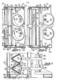
- Figures 1-4 illustrate a housing 20 for a high efficiency air filter 21, and which includes a pair of dampers 22 in accordance with a preferred embodiment of the invention.
- the housing 20 is adapted to be utilized, for example, in an air ventilating or air cleaning system of the type illustrated in Figure 26 and as further described below.
- the housing defines a generally rectangular air passageway therethrough, and includes three side access openings 25, 26, 27 and removable doors 28, 29, 30 for admitting or removing components as hereinafter further described.
- Each of the openings 25, 26, 27 includes a grooved peripheral ring 32 for attachment of a plastic bag (not shown) for containing the removed component in accordance with the standard and well known bag-in and bag-out procedure.
- a HEPA filter 21 of conventional design is adapted to be mounted at a central location in the housing.
- the filter includes a four-sided wood, metal, or molded plastic frame 34, and which supports a folded pack of filtering media 35.
- the frame of the filter typically measures .60 x .60 x 29 cm, and includes a fluid filled channel 36 about its front periphery for sealably engaging a mating rectangular retainer 38 which is fixedly mounted in the interior of the housing in the manner further described in the U.S. patents to Allan et al, Nos. RE 27,701; 4,082,525; and 4,233,044.
- Each mechanism 40, 41 comprises a pair of parallel elongate angle bars 43, 44 which are interconnected by a number of pivotal linkages 45 which are pivotable about the post 46.
- a locking handle 48 is pivotally mounted at the door opening of the housing for rotation about a vertical axis, and a linkage 49 interconnects the pivot rod of the handle to the angle bar 43 of each mechanism, and such that rotation of the handle 48 results in the bars 43 moving essentially laterally (i.e., parallel to the face of the filter) and the bars 44 moving longitudinally toward or away from the filter.
- a latch 50 is also mounted at the door opening for engaging the handle when the bars are moved to their separated or locked position.
- the rear side of the filter 21 incorporates a pair of clips 52 for slideably receiving the angle bar 44, and such that movement of the bar 44 acts to correspondingly move the filter.
- the door 29 is removed, and the handle 48 is rotated counterclockwise as seen in Figure 4 to move the angle bar 44 toward the right.
- the filter 21 may then be slid laterally into the housing, with the clips 52 sliding along the bar 44.
- the handle 48 is rotated clockwise, causing the bar 44 to move to the left and thereby seat the filter against its sealing retainer 38.
- the handle 48 is then locked in the seated position by engagement with the latch 50.
- this procedure may be accomplished while working through a bag mounted on the ring 32 of the door opening 26 in accordance with the standard bag-in procedure.
- the process is reversed to first unseat the filter to a position where it may be laterally withdrawn through the opening 26 and into a receiving bag.
- a damper 22 which embodies the present invention is mounted within the housing on each side of the filter 21.
- Each damper 22 includes a damper assembly 54 as best seen in Figures 1 and 12, which comprises a rectangular peripheral frame 55 which typically measures about 60 by 60 by 15 cm , and so as to closely conform to the size of the interior of the housing.
- the frame 55 is preferably fabricated from a suitable metallic material, and mounts a fluid-filled channel 56 about the front periphery for sealably engaging a retainer 57 fixed in the housing in a manner similar to that described above with respect to the filter 21.
- the damper assembly 54 also includes an orifice panel 58 extending transversely across the frame 55 to fill the area defined thereby.
- the orifice panel 58 which is preferably formed of a relatively heavy sheet metal material, is formed into a plurality of troughs 59 of V-shaped cross section, with the troughs being disposed in a side by side parallel arrangement, and with each trough extending substantially the full distance between two opposite sides of the frame 55.
- each trough 59 includes two generally flat side walls 60, 61, with each side wall 60, 61 having an elongate rectangular opening 62, 63 disposed therein which extends along essentially the full length of the trough.
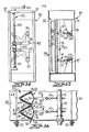
- a plurality of closures 65 are mounted on the frame, with one closure operatively associated with each trough 59 for selectively opening and closing the openings 62, 63 in the two associated side walls.
- Each of the closures 65 includes a pair of flat plates 67, 68 which are pivotally mounted for movement about a pin 70 which extends longitudinally along the trough and adjacent the bight 64 thereof.
- Each closure 65 further includes a spring biasing member 71 interconnected between the plates for biasing the plates toward each other, and a hinge 72 composed of two segments 74, 75 which are pivotally interconnected by a hinge pin 76. The segments are in turn pivotally connected to respective ones of the free edges of the pair of plates by means of the edge pins 78.
- each plate 67, 68 covers and closes the opening 62, 63 in the adjacent trough side wall, and in the collapsed position (note Figures 6 and 8) the plates are contiguous to each other and spaced from the associated openings to open the same.
- Each of the plates 67, 68 includes a resilient elastomeric sheet 81 adhered to the outer surface thereof, with each sheet 81 being sized to surround the associated opening and be compressed to effect sealing of the opening when the plates are in its closed position. More particularly, the plates 67, 68 will be seen to move in a direction generally perpendicular to the surface of the associated trough side wall, to firmly compress each sheet 81 between the plate and the peripheral edge portion of the opening.
- each damper assembly 54 is removably mounted within the housing by an arrangement which is generally similar to that described above with respect to the filter 21. More particularly, each damper assembly may be inserted into the housing through an associated door opening 25 or 27, and a pair of cooperating clamping mechanisms 40, 41 as seen in Figures 11 and 12 are provided for selectively seating and unseating the assembly against its seal.
- Each damper 22 further includes control means 82 operable from without the housing for actuating the closures 65 when the damper assembly is sealably mounted in the housing, and so as to selectively either shut off, fully open, or modulate the air flow through the damper.
- This control means includes means for engaging each of the hinges 72 adjacent the hinge pin 76 to spread apart the hinges, and thus each of the pair of plates, against the force provided by the spring biasing members 71.
- this control means includes a pair of vertically spaced apart parallel shafts 83, 84 which are rotatably mounted to extend across the interior of the housing in a direction which is perpendicular to the lengthwise direction of the troughs 59 and adjacent the rear side of the damper assembly, i.e., the side which includes the closures 65.
- the shafts 83, 84 are rotatably interconnected to rotate in unison, and rotation is effected by a motorized control 86 positioned exteriorly of the housing and as schematically indicated in Figure 2.
- Each shaft 83, 84 fixedly mounts a number of cams 87 of like outline, and with each cam being laterally aligned with a corresponding closure 65.
- the outlines of the cams 87 are generally circular and eccentric to the axis of its shaft. Further, the outline includes a chord segment 88 which, in the position of Figure 6, permits the damper assembly to be initially inserted into the housing or unseated from its seal.
- FIGS 13-16 illustrate another preferred embodiment of an air flow control apparatus in accordance with the present invention, and which is generally designated 22a.
- the apparatus 22a is intended to be permanently mounted in a rectuangular air duct, and it includes a frame 90 having peripheral flanges 91, 92 on the ends for mating with the adjacent duct sections 93, 94.
- the control meansPror actuating the closures 65 of the apparatus 22a includes a pair of vertically spaced apart parallel shafts 96, 97 which are rotatably mounted to extend across the interior of the frame 90 in a direction which is perpendicular to the lengthwise direction of the troughs 59 and adjacent the closures 65.
- the shafts 96, 97 extend through the side of the frame, and are rotatably interconnected to rotate in opposite directions by means of the associated L-shaped arms 98, 99 which are disposed in opposite orientations on the outer ends of the shafts.
- Each arm 98, 99 includes a slot 100 adjacent its free end, for the purposes set forth below.
- a vertically mounted stud 102 having oppositely threaded portions 103, 104, is rotatably mounted on the outside of the frame, and is connected to a hand crank 105.
- the threaded portions mount nuts 106, 107, respectively, which are slideably connected in the slots 100 of respective arms 98, 99.
- the control means further includes a pair of linkages 110 operatively associated with each closure 65.
- each linkage 110 is composed of two pivotally interconnected components, with one component 112 being pivotally connected to the hinge 75 adjacent the hinge pin 76, and with the other component 114 comprising a threaded post which extends through an aperture in the associated shaft.
- a nut 115 is positioned on the threaded post 114 on each side of the shaft to permit adjustment of the effective length of the linkage, and thus the tightness of the seal of the closure.
- rotation of the hand crank 105 causes the arms 98, 99 and thus the shafts 96, 97 to rotate in opposite directions, so as to cause the linkages 110 to move the closures 65 between a closed position as seen in solid lines in Figure 15, and an open position as seen in dashed lines.
- the operation of the crank acts to positively actuate the closures in each direction of movement.
- FIGS 17-19 somewhat schematically illustrate a further embodiment of a closure adapted for use with the present invention, which is indicated by the numeral 65a.
- the closure 65a differs from the above described closure 65 in that the forward edges of the plates 67, 68 are interconnected by a second hinge 120.
- the second hinge 120 is adapted to be operatively connected to a linkage (not shown) which is similar to the linkage 110 described above, for causing the forward edges of the plates to be moved toward and away from the peripheral edge portion of the openings in the manner schematically illustrated by the arrows, to firmly compress the elastomeric sheets 81 and thereby provide a secure seal in the closed position.
- Figures 20-22 illustrate a further embodiment wherein the orifice panel 58a includes a single elongate opening 122 in each trough, with the opening 122, in cross section, including a substantial portion of each of the side walls and extending across the bight portion. Also a single elastomeric sheet 81a is provided, which overlies each of the plates 67, 68 and extends across the bight portion. In this embodiment, it is also preferred that the pivot pin 70 be biased in the direction of the arrow 124 by a suitable linkage (not shown), so that in the closed position a firm sealing engagement is provided between the sheet 81a and the entire peripheral edge portion of the opening 122.
- FIG. 23-25 differs from that of Figures 20-22 only in the specific means for biasing the pin 70 toward the bight of the trough.
- a threaded post 126 extends from the pin 70 and through an aperture in the sheet 81a and panel 58a, at each end of the opening. Nuts 128 are employed to draw the posts and-thus the pins into the bight, to thereby effect a permanent sealing compression of the sheet 81a along the bight portion.
- Figures 26-28 schematically illustrate a number of representative air ventilation systems in which the damper of the present invention may be effectively utilized. With all utilizations, an air flow is directed through the housing as indicated by arrow 19 in Figure 1.
- Figure 26 illustrates an air cleaning system of a type commonly utilized in the nuclear industry for cleaning potentially contaminated air before it is exhausted into the atmosphere.
- the system includes a pair of parallel air ducts 130, 131 connected to a common blower 133, with each duct mounting a housing 20 which contains a HEPA filter 21 and a pair of isolation dampers 22 as described above.
- the parallel ducts are desirable since access to the interior of each housing is periodically required for the purpose of changing the filters or damper assemblies, or maintaining or cleaning the other internal housing components.
- a bypass system 132 may be provided for each housing, to permit the entry of detoxifying agents or steam when the housing is used in biohazardous areas.
- the housing may include a nipple connection (not shown) for the purpose of conducting a pressure decay leak test of the housing in the field.
- FIG. 27 schematically illustrates a further potential use for the damper of the present invention, and which involves the various zones of a nuclear generating plant.
- zone various areas 140, 141, 142 in accordance with the decree of potential hazard.
- a first area 140 the interior of a hot cell which contains highly radioactive material, is usually designated as Zone I.
- Zone II Other areas 141 of the plant where less high levels of radiation might be present are designated as Zone II, and general laboratory and maintenance areas 142 are designated as Zone III.
- Multi-zoned buildings are ventilated so that air flow is from the less contaminated zone to the more contaminated zone, and to insure against circulation in a reverse direction, a pressure differential must be maintained between the zones.
- a damper 22 or 22a of the present invention may be positioned in the ventilation system between each of the zones in the manner illustrated. Each of the dampers may be automatically modulated to maintain the required pressure differential. Also, HEPA filter housings may be positioned between each zone, and at the exhaust outlet from Zone I as illustrated by box 144.
- dampers in accordance with the present invention may be found in an otherwise conventional heating and ventilating system for an industrial plant 150 or other large building, and as schematically shown in Figure 28.
- one damper 22a is employed at the entrance to the outside air duct 151
- a second damper 22a is positioned in the return air duct 152
- a third damper 22a is in the exhaust duct 153.
- An automatic control system is usually provided for modulating the three dampers in a known manner to provide the desired temperature and humidity conditions within the building.
Landscapes
- Engineering & Computer Science (AREA)
- Chemical & Material Sciences (AREA)
- Combustion & Propulsion (AREA)
- Mechanical Engineering (AREA)
- General Engineering & Computer Science (AREA)
- Air-Flow Control Members (AREA)
Applications Claiming Priority (2)
| Application Number | Priority Date | Filing Date | Title |
|---|---|---|---|
| US06/398,404 US4457336A (en) | 1982-07-14 | 1982-07-14 | Air flow control apparatus |
| US398404 | 1999-09-16 |
Publications (2)
| Publication Number | Publication Date |
|---|---|
| EP0099130A2 true EP0099130A2 (de) | 1984-01-25 |
| EP0099130A3 EP0099130A3 (de) | 1984-07-11 |
Family
ID=23575267
Family Applications (1)
| Application Number | Title | Priority Date | Filing Date |
|---|---|---|---|
| EP19830106931 Withdrawn EP0099130A3 (de) | 1982-07-14 | 1983-07-14 | Vorrichtung zum Steuern der Luftströmung |
Country Status (5)
| Country | Link |
|---|---|
| US (1) | US4457336A (de) |
| EP (1) | EP0099130A3 (de) |
| JP (1) | JPS5929939A (de) |
| AU (1) | AU1685683A (de) |
| CA (1) | CA1198310A (de) |
Cited By (2)
| Publication number | Priority date | Publication date | Assignee | Title |
|---|---|---|---|---|
| GB2264349A (en) * | 1992-02-24 | 1993-08-25 | Air Grilles Pty Ltd | Valve for air conditioning systems |
| EP3364081A4 (de) * | 2015-10-30 | 2018-11-14 | Wuxi Fucare Industrial Co., Ltd | Klopffestes ventil mit beidseitiger stosswellenbeständigkeit und ventilkörper dafür |
Families Citing this family (15)
| Publication number | Priority date | Publication date | Assignee | Title |
|---|---|---|---|---|
| US4535811A (en) * | 1984-01-20 | 1985-08-20 | Flanders Filters, Inc. | Air flow control apparatus |
| DE3533974C1 (de) * | 1985-09-24 | 1987-04-09 | Daimler Benz Ag | Kuehlergrill fuer Kraftwagen |
| EP0276346B1 (de) * | 1987-01-28 | 1991-10-09 | Leybold Aktiengesellschaft | Regelbare Drossel für eine Vakuumpumpe, insbesondere Kryopumpe |
| DE3836861A1 (de) * | 1988-10-27 | 1990-05-03 | Stober & Morlock | Absperrvorrichtung fuer kanaele mit grossen querschnitten, insbesondere rauchgaskanaele |
| US5123435A (en) * | 1991-03-27 | 1992-06-23 | Tate Access Floors, Inc. | Laminar damper and method of airflow control |
| DE19648813C2 (de) * | 1996-11-26 | 2000-02-24 | Daimler Chrysler Ag | Klimatisierungsanlage für ein Kraftfahrzeug |
| US6237630B1 (en) | 1999-07-13 | 2001-05-29 | William L. Stone | HVAC damper |
| US6435211B2 (en) | 1999-07-13 | 2002-08-20 | William L. Stone | HVAC damper |
| DE10334570A1 (de) * | 2003-07-28 | 2005-02-24 | Behr Gmbh & Co. Kg | Vorrichtung zur Steuerung der Durchflussmenge eines fluiden Mediums durch eine Leitung |
| US7332012B2 (en) * | 2004-07-21 | 2008-02-19 | Aaf-Mcquay Inc. | Multi-stage filtering apparatus |
| EP1912717B1 (de) * | 2005-08-09 | 2016-08-24 | Camfil USA, Inc. | Integriertes sicherheitsbehältnissystem |
| CA2574693A1 (en) | 2006-01-23 | 2007-07-23 | Aaf-Mcquay Inc. | Front access frame sealing mechanism for filter cassettes |
| US20080254735A1 (en) * | 2007-04-16 | 2008-10-16 | Coward Charles W | Air flow control device with very tight close off |
| US10058809B2 (en) | 2012-09-27 | 2018-08-28 | Environmental Management Confederation, Inc. | Air cleaner frame |
| CN106949565A (zh) * | 2017-05-17 | 2017-07-14 | 海信(山东)空调有限公司 | 空气净化器 |
Family Cites Families (12)
| Publication number | Priority date | Publication date | Assignee | Title |
|---|---|---|---|---|
| US2281615A (en) * | 1939-08-09 | 1942-05-05 | Jr Gustave Adolphus Peple | Method and apparatus for air conditioning |
| US2586997A (en) * | 1947-05-26 | 1952-02-26 | Barber Colman Co | Damper |
| US2890716A (en) * | 1956-03-16 | 1959-06-16 | Buensod Stacey Inc | Control device |
| GB868543A (en) * | 1957-10-30 | 1961-05-17 | Sydney William Gridley | Fluid flow control devices |
| US2974680A (en) * | 1959-02-05 | 1961-03-14 | Buensod Stacey Corp | Valve |
| DE1423841B2 (de) * | 1960-07-12 | 1971-02-25 | Stroemungsmengenregler | |
| US3223113A (en) * | 1962-01-29 | 1965-12-14 | Arthur J Hopper | Valve and control member therefor |
| US3426507A (en) * | 1964-12-23 | 1969-02-11 | Joy Mfg Co | Electrical precipitator |
| DE2130826A1 (de) * | 1971-06-22 | 1973-01-11 | Metallgesellschaft Ag | Vorrichtung zur drosselung und gleichrichtung |
| US3910782A (en) * | 1973-09-27 | 1975-10-07 | Buildex Inc | Baffle type grease filter |
| JPS5535615B2 (de) * | 1974-04-23 | 1980-09-16 | ||
| DE2601310C2 (de) * | 1976-01-15 | 1986-07-10 | Michael 6350 Bad Nauheim Palmer | Drosselorgan für Fluidkanäle |
-
1982
- 1982-07-14 US US06/398,404 patent/US4457336A/en not_active Expired - Fee Related
-
1983
- 1983-07-13 CA CA000432389A patent/CA1198310A/en not_active Expired
- 1983-07-14 EP EP19830106931 patent/EP0099130A3/de not_active Withdrawn
- 1983-07-14 AU AU16856/83A patent/AU1685683A/en not_active Abandoned
- 1983-07-14 JP JP58128691A patent/JPS5929939A/ja active Pending
Cited By (3)
| Publication number | Priority date | Publication date | Assignee | Title |
|---|---|---|---|---|
| GB2264349A (en) * | 1992-02-24 | 1993-08-25 | Air Grilles Pty Ltd | Valve for air conditioning systems |
| GB2264349B (en) * | 1992-02-24 | 1995-08-02 | Air Grilles Pty Ltd | Valve for air conditioning system |
| EP3364081A4 (de) * | 2015-10-30 | 2018-11-14 | Wuxi Fucare Industrial Co., Ltd | Klopffestes ventil mit beidseitiger stosswellenbeständigkeit und ventilkörper dafür |
Also Published As
| Publication number | Publication date |
|---|---|
| EP0099130A3 (de) | 1984-07-11 |
| AU1685683A (en) | 1984-01-19 |
| JPS5929939A (ja) | 1984-02-17 |
| CA1198310A (en) | 1985-12-24 |
| US4457336A (en) | 1984-07-03 |
Similar Documents
| Publication | Publication Date | Title |
|---|---|---|
| US4457336A (en) | Air flow control apparatus | |
| EP3189284B1 (de) | Filtergehäuse | |
| US4521234A (en) | Housing for high efficiency particulate air filters | |
| DE3540729C2 (de) | ||
| US7588614B2 (en) | Filter housing assembly | |
| US4077432A (en) | Purged valve | |
| CA2377459C (en) | Adjustable damper for airflow systems | |
| US4124361A (en) | Sealing device for filter cells | |
| US3782411A (en) | Duct access section | |
| US3894481A (en) | Multi-blade damper | |
| US4535811A (en) | Air flow control apparatus | |
| EP1941193B1 (de) | Linearantrieb für integrierten dämpfer | |
| USH895H (en) | Filtered inflow and emergency HEPA exhaust during asbestos removal | |
| DE2243223A1 (de) | Filtervorrichtung zur entfernung von bakterien aus der belueftungsluft | |
| US5918632A (en) | Single-louver damper with double seal | |
| CN213160113U (zh) | 一种二甲苯废气净化装置 | |
| CN222783094U (zh) | 一种便于开合的风阀 | |
| EP0770828A2 (de) | Gerät für die Klimatisierung von Räumen und Verfahren zu seinem Betrieb | |
| DE10135867C1 (de) | Brandschutzvorrichtung für Lüftungsanlagen | |
| CN206556225U (zh) | 一种暖通空调用过滤器 | |
| DD214660A1 (de) | Elastisches zwei-wege-rueckschlagventil fuer zwei gasstroeme | |
| DD254692A1 (de) | Kombinationsklappen fuer schutzraeume |
Legal Events
| Date | Code | Title | Description |
|---|---|---|---|
| PUAI | Public reference made under article 153(3) epc to a published international application that has entered the european phase |
Free format text: ORIGINAL CODE: 0009012 |
|
| AK | Designated contracting states |
Designated state(s): AT BE CH DE FR GB IT LI LU NL SE |
|
| PUAL | Search report despatched |
Free format text: ORIGINAL CODE: 0009013 |
|
| AK | Designated contracting states |
Designated state(s): AT BE CH DE FR GB IT LI LU NL SE |
|
| 17P | Request for examination filed |
Effective date: 19841026 |
|
| STAA | Information on the status of an ep patent application or granted ep patent |
Free format text: STATUS: THE APPLICATION IS DEEMED TO BE WITHDRAWN |
|
| 18D | Application deemed to be withdrawn |
Effective date: 19880725 |
|
| RIN1 | Information on inventor provided before grant (corrected) |
Inventor name: WOOD, JOSEPH ARTHUR Inventor name: BOWERS, CECIL WILLIAM Inventor name: ALLAN, THOMAS TEMPLE |