EP0099181B1 - Messinstrument mit Niederigladungs-Detector - Google Patents
Messinstrument mit Niederigladungs-Detector Download PDFInfo
- Publication number
- EP0099181B1 EP0099181B1 EP83303393A EP83303393A EP0099181B1 EP 0099181 B1 EP0099181 B1 EP 0099181B1 EP 83303393 A EP83303393 A EP 83303393A EP 83303393 A EP83303393 A EP 83303393A EP 0099181 B1 EP0099181 B1 EP 0099181B1
- Authority
- EP
- European Patent Office
- Prior art keywords
- amplitude
- oscillations
- battery
- indicator
- measuring instrument
- Prior art date
- Legal status (The legal status is an assumption and is not a legal conclusion. Google has not performed a legal analysis and makes no representation as to the accuracy of the status listed.)
- Expired
Links
- 230000010355 oscillation Effects 0.000 claims description 19
- 239000003990 capacitor Substances 0.000 description 7
- 238000010586 diagram Methods 0.000 description 3
- OJIJEKBXJYRIBZ-UHFFFAOYSA-N cadmium nickel Chemical compound [Ni].[Cd] OJIJEKBXJYRIBZ-UHFFFAOYSA-N 0.000 description 2
- 229910052754 neon Inorganic materials 0.000 description 2
- GKAOGPIIYCISHV-UHFFFAOYSA-N neon atom Chemical compound [Ne] GKAOGPIIYCISHV-UHFFFAOYSA-N 0.000 description 2
- 230000009286 beneficial effect Effects 0.000 description 1
- 238000005259 measurement Methods 0.000 description 1
- 230000003534 oscillatory effect Effects 0.000 description 1
Images

Classifications
-
- G—PHYSICS
- G01—MEASURING; TESTING
- G01R—MEASURING ELECTRIC VARIABLES; MEASURING MAGNETIC VARIABLES
- G01R19/00—Arrangements for measuring currents or voltages or for indicating presence or sign thereof
- G01R19/165—Indicating that current or voltage is either above or below a predetermined value or within or outside a predetermined range of values
- G01R19/16533—Indicating that current or voltage is either above or below a predetermined value or within or outside a predetermined range of values characterised by the application
- G01R19/16538—Indicating that current or voltage is either above or below a predetermined value or within or outside a predetermined range of values characterised by the application in AC or DC supplies
- G01R19/16542—Indicating that current or voltage is either above or below a predetermined value or within or outside a predetermined range of values characterised by the application in AC or DC supplies for batteries
Definitions
- This invention relates to low charge detectors for batteries utilised in measuring instruments incorporating a meter from which measurements may be read.
- the detectors known heretofore generally comprise a separate additional meter, a buzzing alarm, or a neon indicator light, none of which is particularly convenient and all of which may add substantial expense to the instrument.
- a neon indicator light may not be visible in bright sunlight, and a buzzing alarm may not be audible when the instrument is being used in noisy conditions.
- a measuring instrument including a meter having a moveable measuring indicator associated therewith, rechargeable means for supplying power to the instrument and a low charge detector, characterised in that said detector includes means for causing said indicator to execute visible oscillations of a first amplitude when said rechargeable means reaches a first predetermined level of exhaustion and means for causing the indicator to execute visible oscillations of a second amplitude when said rechargeable means reaches a second predetermined level of exhaustion.
- the second amplitude is substantially larger than the first amplitude.
- the second level of exhaustion is chosen to be when the battery pack is substantially dead, so that once oscillations of the second amplitude are applied to the indicator, the instrument should not be used again until the - battery pack has been recharged.
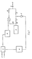
- outputs from two series- connected batteries are shown at 1 and 2 respectively.
- the output 1 is derived from a battery which, because of its location, discharges at a relatively fast rate and the output 2 is derived from a second battery, connected in series with the first, and which discharges at a substantially slower rate.
- the first battery is connected via a switch arrangement 3 to a "low battery detector” circuit 4.
- a switch arrangement 3 When the first battery has discharged to a predetermined level, an output from the "low battery detector” circuit 4 is applied to diode 5.
- An output from diode 5 then allows a first output 6a to be released from a 1Hz oscillator 6, via resistors 7 and 8 and capacitor 9, and to be subsequently applied, via an output 13 and an amplifier (not shown in the figure), to a pointer on a meter of a measuring instrument (also not shown), thus causing the pointer to execute oscillations of a relatively small amplitude.
- the switch arrangement 3 connects the second battery to a "dead battery detector” circuit 10, which monitors the state of charge of the second battery and, when it has discharged to a predetermined level, an output from "dead battery detector” circuit 10 causes an integrated circuit 11 to allow a second output 6b from the 1Hz oscillator 6 to pass, via resistor 12 and capacitor 9, to output 13 and the amplifier (not shown) and thereby to the pointer.
- the second output 6b therefore combines with the first output 6a to cause the pointer to execute oscillations of a substantially greater amplitude, thereby indicating to the user of the instrument that the battery pack is substantially dead and that the instrument should not be used again until the battery has been recharged.
- the voltage applied to the working circuits is always approximately equal to the voltage of battery 2, irrespective of whether battery 1 is in circuit.
- the battery inputs, 1 and 2 are connected in series to the circuit via battery terminals 14 and 15 and battery tap 33, and the battery pack supplying power to the instrument is connected via circuit outputs 30 and 31.
- Output 31 is connected to earth at 32 while the instrument is in use, i.e. during the time that power is drained from the battery pack.
- Output 1 is initially applied to transistor 16, which is conducting, and resistor 17, until, at a predetermined level of discharge, transistor 18, which is also conducting, turns off.
- the output of transistor 18 therefore goes low and it is inverted by integrated circuit 19 to produce a high output which turns on transistors 21 and 22 and consequently transistor 23.
- transistor 23 is turned on, battery 1 is by-passed, and battery 2 is connected to the "dead battery detector" circuit.
- the high output from integrated circuit 19 is also applied, via 10 and 24, to the cathode of a conducting diode 5, which is thus turned off.
- the 1Hz oscillator 6 consists of two integrated circuits, 25 and 26, which are connected as inverters, together with capacitor 27 and resistor 28.
- inputs A and B of integrated circuit 25 are low, output C is high, inputs D and E of integrated circuit 26 are high and output F is low and the upper end of resistor 28 is high.
- Capacitor 27 charges via resistor 28 to a sufficient level to make inputs A and B high. This causes the state of outputs C and F to reverse, so that output C is low and output F is high, and so capacitor 27 consequently discharges to make inputs A and B low again. This cycle of operations is then repeated to produce an oscillatory output.
- Input G of integrating circuit 11 now allows a second output 6b (as well as the first output 6a) to pass from the 1 Hz oscillator 6, via resistor 12, capacitor 9 and output 13.
- the first and second outputs, 6a and 6b respectively, are therefore combined, via output 13, and this combined output is applied to the pointer, via the amplifier, to produce oscillations of the pointer of a substantially larger amplitude.
Landscapes
- Engineering & Computer Science (AREA)
- Power Engineering (AREA)
- Physics & Mathematics (AREA)
- General Physics & Mathematics (AREA)
- Charge And Discharge Circuits For Batteries Or The Like (AREA)
- Tests Of Electric Status Of Batteries (AREA)
Claims (6)
Applications Claiming Priority (2)
| Application Number | Priority Date | Filing Date | Title |
|---|---|---|---|
| GB8219857 | 1982-07-08 | ||
| GB8219857 | 1982-07-08 |
Publications (2)
| Publication Number | Publication Date |
|---|---|
| EP0099181A1 EP0099181A1 (de) | 1984-01-25 |
| EP0099181B1 true EP0099181B1 (de) | 1985-11-27 |
Family
ID=10531559
Family Applications (1)
| Application Number | Title | Priority Date | Filing Date |
|---|---|---|---|
| EP83303393A Expired EP0099181B1 (de) | 1982-07-08 | 1983-06-13 | Messinstrument mit Niederigladungs-Detector |
Country Status (3)
| Country | Link |
|---|---|
| US (1) | US4535325A (de) |
| EP (1) | EP0099181B1 (de) |
| DE (1) | DE3361343D1 (de) |
Families Citing this family (8)
| Publication number | Priority date | Publication date | Assignee | Title |
|---|---|---|---|---|
| US4660027A (en) * | 1984-08-31 | 1987-04-21 | Motorola, Inc. | Reduced power consumption low battery alert device |
| GB8528472D0 (en) * | 1985-11-19 | 1985-12-24 | British Aerospace | Battery state of charge indicator |
| US5008655A (en) * | 1989-11-20 | 1991-04-16 | Schlesinger Robert A | Visual alarm device interconnectable to existing monitoring circuitry |
| US5053752A (en) * | 1990-02-26 | 1991-10-01 | Jack Epstein | Smoke detector and method using elongated flexible low battery condition indicator member |
| US5610600A (en) * | 1994-06-07 | 1997-03-11 | Koenig; Robert H. | Operation verification system and method for navigational instruments |
| US5686896A (en) * | 1995-09-28 | 1997-11-11 | Interactive Technologies, Inc. | Low battery report inhibitor for a sensor |
| US5867008A (en) * | 1996-06-05 | 1999-02-02 | Double-Time Battery Corporation | Overcharge protection circuitry for rechargeable battery pack |
| GB2319347A (en) * | 1996-11-14 | 1998-05-20 | Rupert Edward Robertson | Calibrated battery tester |
Family Cites Families (12)
| Publication number | Priority date | Publication date | Assignee | Title |
|---|---|---|---|---|
| US1922792A (en) * | 1932-03-30 | 1933-08-15 | Edward H Cain | Testing apparatus |
| US2827610A (en) * | 1953-04-15 | 1958-03-18 | Gen Electric | Oscillatory friction eliminator |
| US3383580A (en) * | 1964-03-16 | 1968-05-14 | Susquehanna Corp | Battery-life indicator |
| GB1128165A (en) * | 1965-04-09 | 1968-09-25 | Harold Morton | Apparatus for indicating the state of charge of secondary batteries |
| US3412328A (en) * | 1965-08-09 | 1968-11-19 | Troxler Electronic Lab Inc | Counting ratemeter with manual override of long time constant |
| US3412332A (en) * | 1965-09-09 | 1968-11-19 | Parker Instr Corp | Pointer lock for electrical indicating instruments |
| US3550105A (en) * | 1967-08-08 | 1970-12-22 | Warwick Electronics Inc | Battery condition indicator |
| US3739264A (en) * | 1971-06-11 | 1973-06-12 | Agridustrial Electronics | Grain moisture tester |
| US3916400A (en) * | 1974-04-26 | 1975-10-28 | Safe Flight Instrument | Malfunction warning device for use with electrical meters |
| DE2717191A1 (de) * | 1977-04-19 | 1978-11-02 | Agfa Gevaert Ag | Vorrichtung zur anzeige der batteriespannung in fotografischen oder kinematografischen kameras |
| JPS5553137A (en) * | 1978-10-12 | 1980-04-18 | Matsushita Electric Works Ltd | Charger with storage battery state indicating function |
| JPS5640773A (en) * | 1979-09-12 | 1981-04-17 | Canon Inc | Battery checker |
-
1983
- 1983-06-13 EP EP83303393A patent/EP0099181B1/de not_active Expired
- 1983-06-13 DE DE8383303393T patent/DE3361343D1/de not_active Expired
- 1983-07-05 US US06/510,586 patent/US4535325A/en not_active Expired - Fee Related
Also Published As
| Publication number | Publication date |
|---|---|
| US4535325A (en) | 1985-08-13 |
| EP0099181A1 (de) | 1984-01-25 |
| DE3361343D1 (en) | 1986-01-09 |
Similar Documents
| Publication | Publication Date | Title |
|---|---|---|
| US4949046A (en) | Battery state of charge indicator | |
| US5640150A (en) | Resettable state-of-charge indicator for rechargeable batteries | |
| US7459884B2 (en) | Remaining capacity calculation method for secondary battery, and battery pack | |
| US4638237A (en) | Battery condition indicator | |
| CA1262934C (en) | DEVICE FOR DETERMINING THE CHARGE STATE OF A BATTERY | |
| US4535325A (en) | Low charge detector | |
| JPS5575665A (en) | Detection circuit for battery capacity | |
| WO1998008146A1 (en) | Rechargeable electronic device | |
| US4678999A (en) | Charge depletion meter | |
| US4453129A (en) | Method for measuring the charge state of an accumulator and a device for implementing such method | |
| JP3416959B2 (ja) | バッテリー装置 | |
| EP1584941A1 (de) | Vorrichtung zur Energiemessung von Batterien, insbesondere während des Ladens/Entladens einer Batterie | |
| GB2000596A (en) | Battery state of charge indicator device | |
| JPS5522153A (en) | Electronic watch | |
| SU748661A1 (ru) | Система зар да | |
| JPS5522154A (en) | Electronic watch | |
| JPS63121434A (ja) | 電源装置 | |
| JPS5767880A (en) | Electronic timepiece with solar battery | |
| JPS5480156A (en) | Electronic watch | |
| SU1515117A1 (ru) | Устройство контрол источника питани | |
| WO1990001709A1 (en) | Radiation measuring device | |
| JPS5776470A (en) | Wristwatch with solar battery | |
| TW327705B (en) | Voltage monitoring circuit in an integrated circuit device | |
| JPS61236332A (ja) | 電子腕時計 | |
| RU2102773C1 (ru) | Прибор для индикации радиации |
Legal Events
| Date | Code | Title | Description |
|---|---|---|---|
| PUAI | Public reference made under article 153(3) epc to a published international application that has entered the european phase |
Free format text: ORIGINAL CODE: 0009012 |
|
| AK | Designated contracting states |
Designated state(s): DE FR GB NL |
|
| 17P | Request for examination filed |
Effective date: 19840509 |
|
| GRAA | (expected) grant |
Free format text: ORIGINAL CODE: 0009210 |
|
| AK | Designated contracting states |
Designated state(s): DE FR GB NL |
|
| REF | Corresponds to: |
Ref document number: 3361343 Country of ref document: DE Date of ref document: 19860109 |
|
| ET | Fr: translation filed | ||
| PGFP | Annual fee paid to national office [announced via postgrant information from national office to epo] |
Ref country code: NL Payment date: 19860630 Year of fee payment: 4 |
|
| PLBE | No opposition filed within time limit |
Free format text: ORIGINAL CODE: 0009261 |
|
| STAA | Information on the status of an ep patent application or granted ep patent |
Free format text: STATUS: NO OPPOSITION FILED WITHIN TIME LIMIT |
|
| 26N | No opposition filed | ||
| PG25 | Lapsed in a contracting state [announced via postgrant information from national office to epo] |
Ref country code: NL Effective date: 19880101 |
|
| NLV4 | Nl: lapsed or anulled due to non-payment of the annual fee | ||
| PG25 | Lapsed in a contracting state [announced via postgrant information from national office to epo] |
Ref country code: FR Free format text: LAPSE BECAUSE OF NON-PAYMENT OF DUE FEES Effective date: 19880226 |
|
| PG25 | Lapsed in a contracting state [announced via postgrant information from national office to epo] |
Ref country code: DE Effective date: 19880301 |
|
| GBPC | Gb: european patent ceased through non-payment of renewal fee | ||
| REG | Reference to a national code |
Ref country code: FR Ref legal event code: ST |
|
| PG25 | Lapsed in a contracting state [announced via postgrant information from national office to epo] |
Ref country code: GB Effective date: 19881122 |