EP0099253A2 - Micro-électrodes et procédé de fabrication - Google Patents
Micro-électrodes et procédé de fabrication Download PDFInfo
- Publication number
- EP0099253A2 EP0099253A2 EP83303987A EP83303987A EP0099253A2 EP 0099253 A2 EP0099253 A2 EP 0099253A2 EP 83303987 A EP83303987 A EP 83303987A EP 83303987 A EP83303987 A EP 83303987A EP 0099253 A2 EP0099253 A2 EP 0099253A2
- Authority
- EP
- European Patent Office
- Prior art keywords
- capillary tube
- conductive filament
- cavity
- lead wire
- micro
- Prior art date
- Legal status (The legal status is an assumption and is not a legal conclusion. Google has not performed a legal analysis and makes no representation as to the accuracy of the status listed.)
- Granted
Links
Images
Classifications
-
- A—HUMAN NECESSITIES
- A61—MEDICAL OR VETERINARY SCIENCE; HYGIENE
- A61B—DIAGNOSIS; SURGERY; IDENTIFICATION
- A61B5/00—Measuring for diagnostic purposes; Identification of persons
- A61B5/24—Detecting, measuring or recording bioelectric or biomagnetic signals of the body or parts thereof
- A61B5/25—Bioelectric electrodes therefor
- A61B5/262—Needle electrodes
Definitions
- the present invention relates to micro electrodes and the production thereof.
- Micro electrodes may be designed to be directly inserted deeply into a living body. In addition to the passive function of simply picking up biological signals from such a position, they may have the active function of supplying the implanted position with an external electric current to effect an electrochemical reaction. Micro electrodes having such an active function are designated as "micro working electrodes" and are useful in analyzing by means of voltammetry minute quantities of substances produced at the implantation position in the living body as a result of such electrochemical reactions. Measurements can be made by such electrodes can be processed in an external appliance to give valuable information on the bio-electrochemical phenomena of the living body.
- a micro working electrode can also be placed in the fluid path in a liquid chromatography system with a view to detecting minute or trace amounts of of substances present in the running liquid.
- micro working electrodes are to be inserted in and fiexed at specified positions having extremely small dimensions, for instance, around the nuclei of the cranial nerves of the rat, the whole electrode structure has to be designed taking account of many restrictive conditions.
- Such electrodes are usually structured to have core components, i.e. a conductive filament and an outer lead wire, and supporting components, i.e., an envelope of a physiologically inert material, for instance, glass, and a filler of, for instance, a resinous material, for embedding the core components in the envelope.
- core components i.e. a conductive filament and an outer lead wire
- supporting components i.e., an envelope of a physiologically inert material, for instance, glass, and a filler of, for instance, a resinous material, for embedding the core components in the envelope.
- the exposed segment of the conductive filament which projects from the tip of the envelope and serves as the site of the electrochemical reaction, should be small in size in order to give the electrode high selectivity with respect to the spot whereat it contacts the living body, and the filament itself should be as thin as possible.
- conductive filaments thin metal wires have been used hitherto.
- metal wires as thin as 100 ⁇ m have insufficient mechanical strength.
- some metals are inherently not suited for the purpose on account of their electrochemical properties.
- micro working electrodes are required to have a residual current as small as possible and thus the insulation around the exposed segment is important.
- the carbon fibers are excellent in their mechanical properties, e.g., deflective strength,and may be finished to very thin monofilaments, they are unexpectedly difficult to handle in assembling micro electrodes.
- a tapering glass capillary tube is selected as a suitable envelope, the manipulation involved in threading a very thin carbon monofilament into the needle end of the capillary tube has proved much more difficult than expected.
- a glass tube is worked by drawing using a "pipet puller" to obtain a tip diameter of a few ⁇ m and by cutting the tube into a capillary (length, 10 to 30 mm).
- a carbon fiber (length, 20 to 40 mm; diameter 8 ⁇ m) is threaded into the capillary until it is blocked by the fringed tip.
- the glass capillary is cut at the level where the fiber is blocked, thus enabling the fiber to be pushed a few mm through the capillary. This method minimizes the interstitial space between the capillary and the carbon fiber.
- the cavity of the capillary is then packed with a conductive paste (polyester resin containing graphite powder), first by inverting the capillary into a mass of the conductive paste to fill a part of the cavity with the paste and then by forcing the filled paste into the tip of the capillary tube.
- a conductive paste polyester resin containing graphite powder
- the resin is separated from the graphite powder (about 1 wm in diameter) to ensure insulation.
- Connection of the carbon fiber with an outer lead wire is made simply by pushing the wire as far as possible into the capillary cavity filled with the paste. More importantly, the carbon monofilament is connected with the outer lead wire as a result of their being embedded in a common conductive resin.
- an electrode prepared by such a method as described above is not satisfactory in its performance and in its production.
- This invention is based upon the discovery that threading the carbon fiber into the capillary tube is made easy by filling the cavity of the capillary tube with a volatile solvent. By this means a direct connection of the carbon monofilament with the outer lead wire is also made possible and an insulating filler may be used in place of the conductive paste.
- a micro electrode comprising a tapering capillary tube in which the thicker end preferably has an outside diameter of 2 mm or less, a conductive filament, preferably having an outside diameter of 50 ⁇ m or less, an outer lead wire and a filler packed into the cavity of the capillary tube, the conductive filament being directly connected with the outer lead wire in the cavity of the capillary tube and the filler being an insulating resin.
- a method for producing a micro electrode which includes the step of threading a conductive filament into a tapering glass capillary tube so that the tip of the filament projects from the needle end of the tube, at least part of the cavity of the capillary tube being filled with a volatile solvent during the threading step.
- the conductive filament is preferably carbon fiber and a single monofilament is usually used. However, two or more monofilaments may be used in a bundle to enlarge the effective surface area of the electrode and to improve sensitivity.
- a metal wire may also be used as the conductive filament and can easily be connected with the lead wire by conventional means, for instance, soldering.
- the metal wire should however, have a deflective strength equivalent to or higher than that of a carbon fiber of the same diameter.
- the conductive filament e.g., a carbon monofilament or a bundle of monofilaments
- the conductive filament is preferably connected directly with the outer lead wire by, for instance, gluing the former to the latter with a conductive resin containing carbon powder (usually available as a conductive paint or adhesive) prior to the threading step.
- a conductive resin containing carbon powder usually available as a conductive paint or adhesive
- the conductive filament is directly connected with the outer lead wire and the conductive segment in the cavity of the capillary tube is strictly limited to the zone of connection between wire and filament, the remaining part of the cavity does not need to be conductive and is usually filled with an insulating resin in the electrode structure of the present invention.
- This structure ensures a highly reliable connection and a high degree of insulation as compared to conventional structures.
- the size of a pinhole formed at the needle end of the capillary tube may vary widely (about 7 - 100 ⁇ m), productivity in terms of yield is sufficiently high.
- the volatile solvent used in the production process can be, for example, selected from alcohols, e.g., ethanol and methanol, ketones, e.g., acetone and methyl ethyl ketone, ethers, e.g., diethyl ether and tetrahydrofuran, esters, e.g., ethyl acetate, and hydrocarbons, e.g., benzene and hexane. Water can also be used as the volatile solvent in certain cases. Alcohols, particularly ethanol, are preferred in view of ease and safety in operation and the short drying time required.
- alcohols e.g., ethanol and methanol
- ketones e.g., acetone and methyl ethyl ketone
- ethers e.g., diethyl ether and tetrahydrofuran
- esters e.g., ethyl acetate
- hydrocarbons e.g.,
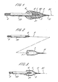
- reference numeral 1 represents a capillary tube
- 2 is an outer lead wire with an insulator coating layer
- 3 is a carbon fiber
- 4 is a carbon powder-containing conductive resin layer
- 5 is an insulator resin layer
- 6 is a protective resin layer.
- the tip 31 (length usually 0.1 to 0.5 mm) of the carbon monofilament 3 projects exposed from the needle end 11 of the capillary tube 1.
- the root segment 32 of the carbon monofilament 3 is glued to a connecting segment 21 of the outer lead wire 2, where its insulator coating layer 22 is removed, with the carbon powder-containing conductive resin layer 4.
- the opposite end of the lead wire 2 is exposed from the thicker end of the capillary tube for connection to outside appliances.
- the carbon monofilament 3 is first glued on to the outer lead wire 2 to give a combined body.
- the tapering capillary tube 1 is prepared by working a micropipette (about 100 ⁇ L in capacity, 1.5 mm outside diameter and 1.1 mm inside diameter) by a pipet puller to form a needle end (about 8 ⁇ m to 200 ⁇ m inside diameter) and by'cutting the micropipette at the pulled portion to give pieces of about 15 mm in length. Then the cavity is filled with a volatile solvent 7 (ethanol, about 10 pL), into which the combined body is introduced (as indicated by the dotted line - Fig.
- a volatile solvent 7 ethanol, about 10 pL
- an insulating resin 5 in a fluid state is poured into the cavity of the glass capillary tube 1 from its thicker end using a syringe along the direction indicated by an arrow Fig. 3 to embed the combined body.
- the fluid resin is evenly distributed up to the tip of the needle end 11 of the capillary tube 1 through capillary action but it will not leak from the interstice between the monofilament 3 and the encircling glass.
- the resin is preferably of low viscosity in its fluid state in order to take best advantage of the capillary action.
- the thicker end of the capillary tube 1 is then protected with another insulator resin layer 6.
- the resin for this purpose the resin used in the aforesaid embedding can be used, although it is preferred to select one having more complete protection capability and a shorter hardening time.
- TORAYCA T 300 or M 40 available from Toray Corporation, may be used as the carbon fiber
- Dotite .SH-3A Epoxide resin base
- Fujikura Kasei K.K. may be used as the conductiye resin
- Araldite AY 103/HY 956, available from Ciba-Geigy may be used as the resin for embedding
- Hi-Super available from Cemedain K .K., may be used as the protective coating layer.
- the thus-obtained micro electrode is finished by cutting the tip 31 of the carbon monofilament 3 by 500 ⁇ m, and subjecting it to a conduction test and to electrolytic treatment (which is a cyclic anodic pre-treatment in dilute sulfuric acid).
- the electrical resistance of the electrode is usually around 4 to 5 K Ohms, which is mainly attributable to the resistance of the carbon monofilament.
- the residual current is of the order of nA (nano ampere).
- an electrode of the same structure as that in the illustrated example is prepared by substituting Dotite SH-3A for Araldite AY 103/HY 956 as the resin for embedding the combined body (the solvent contained to excess in Dotite SH-3A having been extracted therefrom before use).
- the thus-obtained electrode showed a very large value for residual current (about 100 times that of the illustrated embodiment of the invention) and cannot be used in precision measurements.
- the electrical resistance of the electrode is mainly accountable as that of the carbon monofilament, the use of a plurality of monofilaments in a bundle will decrease the electrical resistance. This facilitates the adjustment of the electrode to a measuring appliance.
- the electrode may be finished by cutting the tip of the monofilament up to 100 ⁇ m or shorter in order to improve selectivity for the spot where it is to be positioned.
- the electrode may be in the form of a disk in a sense of electrical equivalence.
Landscapes
- Life Sciences & Earth Sciences (AREA)
- Health & Medical Sciences (AREA)
- Medical Informatics (AREA)
- Animal Behavior & Ethology (AREA)
- Pathology (AREA)
- Engineering & Computer Science (AREA)
- Biomedical Technology (AREA)
- Heart & Thoracic Surgery (AREA)
- Physics & Mathematics (AREA)
- Molecular Biology (AREA)
- Surgery (AREA)
- Biophysics (AREA)
- General Health & Medical Sciences (AREA)
- Public Health (AREA)
- Veterinary Medicine (AREA)
- Measurement And Recording Of Electrical Phenomena And Electrical Characteristics Of The Living Body (AREA)
- Electrotherapy Devices (AREA)
- Measuring Leads Or Probes (AREA)
- Electrodes For Compound Or Non-Metal Manufacture (AREA)
Applications Claiming Priority (2)
| Application Number | Priority Date | Filing Date | Title |
|---|---|---|---|
| JP119035/82 | 1982-07-08 | ||
| JP57119035A JPS598937A (ja) | 1982-07-08 | 1982-07-08 | 微小電極およびその製造方法 |
Publications (3)
| Publication Number | Publication Date |
|---|---|
| EP0099253A2 true EP0099253A2 (fr) | 1984-01-25 |
| EP0099253A3 EP0099253A3 (en) | 1984-10-10 |
| EP0099253B1 EP0099253B1 (fr) | 1986-12-30 |
Family
ID=14751343
Family Applications (1)
| Application Number | Title | Priority Date | Filing Date |
|---|---|---|---|
| EP83303987A Expired EP0099253B1 (fr) | 1982-07-08 | 1983-07-08 | Micro-électrodes et procédé de fabrication |
Country Status (5)
| Country | Link |
|---|---|
| US (1) | US4576174A (fr) |
| EP (1) | EP0099253B1 (fr) |
| JP (1) | JPS598937A (fr) |
| DE (1) | DE3368505D1 (fr) |
| GB (1) | GB2123700B (fr) |
Cited By (2)
| Publication number | Priority date | Publication date | Assignee | Title |
|---|---|---|---|---|
| EP0215726A3 (fr) * | 1985-08-19 | 1989-04-19 | The University Of Melbourne | Groupe d'électrodes pour une prothèse |
| WO2004092363A1 (fr) * | 2003-04-11 | 2004-10-28 | Riken | Stimulation electrique d'une cellule |
Families Citing this family (16)
| Publication number | Priority date | Publication date | Assignee | Title |
|---|---|---|---|---|
| JPS5825037A (ja) * | 1981-08-05 | 1983-02-15 | Hitachi Ltd | 露光光量制御方法 |
| FR2582858B1 (fr) * | 1985-06-04 | 1988-11-10 | Videocolor | Procede et appareil d'illumination de la dalle d'un tube de television en couleurs pour la formation de l'ecran |
| JPS63132363U (fr) * | 1987-02-21 | 1988-08-30 | ||
| DE3816458A1 (de) * | 1988-05-13 | 1989-12-21 | Josowicz Mira | Ultramikroelektrode, verfahren zu deren herstellung und ihre verwendung |
| US4972846A (en) * | 1989-01-31 | 1990-11-27 | W. L. Gore & Associates, Inc. | Patch electrodes for use with defibrillators |
| US6083220A (en) | 1990-03-13 | 2000-07-04 | The Regents Of The University Of California | Endovascular electrolytically detachable wire and tip for the formation of thrombus in arteries, veins, aneurysms, vascular malformations and arteriovenous fistulas |
| USRE42625E1 (en) | 1990-03-13 | 2011-08-16 | The Regents Of The University Of California | Endovascular electrolytically detachable wire and tip for the formation of thrombus in arteries, veins, aneurysms, vascular malformations and arteriovenous fistulas |
| USRE42756E1 (en) | 1990-03-13 | 2011-09-27 | The Regents Of The University Of California | Endovascular electrolytically detachable wire and tip for the formation of thrombus in arteries, veins, aneurysms, vascular malformations and arteriovenous fistulas |
| US5851206A (en) * | 1990-03-13 | 1998-12-22 | The Regents Of The University Of California | Method and apparatus for endovascular thermal thrombosis and thermal cancer treatment |
| US5269810A (en) * | 1992-06-19 | 1993-12-14 | W. L. Gore & Associates, Inc. | Patch electrode |
| WO1994017852A1 (fr) * | 1993-02-01 | 1994-08-18 | W.L. Gore & Associates, Inc. | Electrode implantable |
| US5593550A (en) * | 1994-05-06 | 1997-01-14 | Medtronic, Inc. | Plasma process for reducing friction within the lumen of polymeric tubing |
| US5571157A (en) * | 1995-07-19 | 1996-11-05 | Pacesetter, Inc. | Endocardial lead with reduced diameter tip portion and method for making such lead |
| US5649936A (en) * | 1995-09-19 | 1997-07-22 | Real; Douglas D. | Stereotactic guide apparatus for use with neurosurgical headframe |
| CN106033071B (zh) * | 2015-03-10 | 2019-05-28 | 中国科学院生物物理研究所 | 适用于膜片钳电化学技术系统的新型碳纤电极 |
| CN113203776B (zh) * | 2021-04-09 | 2022-11-01 | 北京科技大学 | 一种碳纤维超微圆盘电极的制备方法 |
Family Cites Families (4)
| Publication number | Priority date | Publication date | Assignee | Title |
|---|---|---|---|---|
| US3540434A (en) * | 1968-12-05 | 1970-11-17 | Us Navy | Coaxial electrode recording system |
| US4417581A (en) * | 1979-05-23 | 1983-11-29 | The University Of Florida | Corneal electrode for electroretinography |
| FR2462171A1 (fr) * | 1979-07-26 | 1981-02-13 | Cardiofrance Co | Dispositif d'introduction et de mise en place d'une sonde ou electrode, perfectionnements apportes aux sondes ou electrodes et outil constituant le dispositif |
| US4461304A (en) * | 1979-11-05 | 1984-07-24 | Massachusetts Institute Of Technology | Microelectrode and assembly for parallel recording of neurol groups |
-
1982
- 1982-07-08 JP JP57119035A patent/JPS598937A/ja active Granted
-
1983
- 1983-06-29 US US06/509,034 patent/US4576174A/en not_active Expired - Fee Related
- 1983-07-08 DE DE8383303987T patent/DE3368505D1/de not_active Expired
- 1983-07-08 EP EP83303987A patent/EP0099253B1/fr not_active Expired
- 1983-07-08 GB GB08318573A patent/GB2123700B/en not_active Expired
Cited By (2)
| Publication number | Priority date | Publication date | Assignee | Title |
|---|---|---|---|---|
| EP0215726A3 (fr) * | 1985-08-19 | 1989-04-19 | The University Of Melbourne | Groupe d'électrodes pour une prothèse |
| WO2004092363A1 (fr) * | 2003-04-11 | 2004-10-28 | Riken | Stimulation electrique d'une cellule |
Also Published As
| Publication number | Publication date |
|---|---|
| JPS598937A (ja) | 1984-01-18 |
| JPH0126290B2 (fr) | 1989-05-23 |
| EP0099253A3 (en) | 1984-10-10 |
| GB8318573D0 (en) | 1983-08-10 |
| GB2123700A (en) | 1984-02-08 |
| GB2123700B (en) | 1986-02-12 |
| DE3368505D1 (en) | 1987-02-05 |
| EP0099253B1 (fr) | 1986-12-30 |
| US4576174A (en) | 1986-03-18 |
Similar Documents
| Publication | Publication Date | Title |
|---|---|---|
| EP0099253B1 (fr) | Micro-électrodes et procédé de fabrication | |
| US6757970B1 (en) | Method of making multi-contact electrode array | |
| US7047081B2 (en) | Band type multicontact electrode and method of making the same | |
| US4835853A (en) | Method for electrically connecting conductors & electrodes in an implantable electrode lead | |
| DE3816458A1 (de) | Ultramikroelektrode, verfahren zu deren herstellung und ihre verwendung | |
| DE68921881T2 (de) | Mit einem film beschichteter sensor. | |
| NL8104609A (nl) | Ringelektrode voor verbindingsdraad van een gangmaker en een werkwijze voor de vervaardiging van de elektrode. | |
| DE2613355C3 (de) | Verfahren zur Herstellung von Kathoden für polaropraphische Messungen | |
| US4041933A (en) | Electrode for polarographic measurements in physiological media | |
| US3415730A (en) | Flexible electrode assembly | |
| Trikantzopoulos et al. | Novel carbon-fiber microelectrode batch fabrication using a 3D-printed mold and polyimide resin | |
| EP0343402B1 (fr) | Assemblage avec connecteur à ergot et méthode de fabrication associée. | |
| US5266180A (en) | Interior electrode of a polarographic electrode | |
| DE2443863C2 (de) | Polarographische Zelle | |
| CN114076786A (zh) | 碳纤维微电极及其制备方法和应用 | |
| KR101412492B1 (ko) | 용존산소 측정용 미세전극 및 그 제작 방법 | |
| Whalen et al. | A hypodermic needle pO2 electrode | |
| DE2418397A1 (de) | Elektrode fuer polarographische messungen in physiologischen medien | |
| US3965383A (en) | Multi-wire oxygen electrode and method of manufacturing the same | |
| GB2182446A (en) | Antimony electrode assembly | |
| JP2949217B2 (ja) | 微小基準電極およびこれを備えた微小複合電極、それらの製造方法ならびに液絡方法 | |
| CA1201168A (fr) | Sondes de gaz de polarographie | |
| EP0221969B1 (fr) | AGENCEMENT D'ELECTRODES DU TYPE A INSERTION POUR MESURE DU pO 2? CONTINUE DANS DU TISSU DE PEAU VIVANT | |
| EP0706028B1 (fr) | Capteur d'inclinaison et procédé pour sa fabrication | |
| US3930976A (en) | Glass electrode assembly |
Legal Events
| Date | Code | Title | Description |
|---|---|---|---|
| PUAI | Public reference made under article 153(3) epc to a published international application that has entered the european phase |
Free format text: ORIGINAL CODE: 0009012 |
|
| AK | Designated contracting states |
Designated state(s): CH DE FR IT LI |
|
| PUAL | Search report despatched |
Free format text: ORIGINAL CODE: 0009013 |
|
| 17P | Request for examination filed |
Effective date: 19840606 |
|
| AK | Designated contracting states |
Designated state(s): CH DE FR IT LI |
|
| 17Q | First examination report despatched |
Effective date: 19860313 |
|
| GRAA | (expected) grant |
Free format text: ORIGINAL CODE: 0009210 |
|
| AK | Designated contracting states |
Kind code of ref document: B1 Designated state(s): CH DE FR IT LI |
|
| ITF | It: translation for a ep patent filed | ||
| REF | Corresponds to: |
Ref document number: 3368505 Country of ref document: DE Date of ref document: 19870205 |
|
| ET | Fr: translation filed | ||
| PLBE | No opposition filed within time limit |
Free format text: ORIGINAL CODE: 0009261 |
|
| STAA | Information on the status of an ep patent application or granted ep patent |
Free format text: STATUS: NO OPPOSITION FILED WITHIN TIME LIMIT |
|
| 26N | No opposition filed | ||
| PG25 | Lapsed in a contracting state [announced via postgrant information from national office to epo] |
Ref country code: LI Effective date: 19890731 Ref country code: CH Effective date: 19890731 |
|
| PG25 | Lapsed in a contracting state [announced via postgrant information from national office to epo] |
Ref country code: FR Free format text: LAPSE BECAUSE OF NON-PAYMENT OF DUE FEES Effective date: 19900330 |
|
| REG | Reference to a national code |
Ref country code: CH Ref legal event code: PL |
|
| PG25 | Lapsed in a contracting state [announced via postgrant information from national office to epo] |
Ref country code: DE Effective date: 19900403 |
|
| REG | Reference to a national code |
Ref country code: FR Ref legal event code: ST |