EP0099324B1 - Annahmeeinrichtung für Banknotenprüfer - Google Patents
Annahmeeinrichtung für Banknotenprüfer Download PDFInfo
- Publication number
- EP0099324B1 EP0099324B1 EP83730054A EP83730054A EP0099324B1 EP 0099324 B1 EP0099324 B1 EP 0099324B1 EP 83730054 A EP83730054 A EP 83730054A EP 83730054 A EP83730054 A EP 83730054A EP 0099324 B1 EP0099324 B1 EP 0099324B1
- Authority
- EP
- European Patent Office
- Prior art keywords
- side rails
- note
- plate
- note receptacle
- slot
- Prior art date
- Legal status (The legal status is an assumption and is not a legal conclusion. Google has not performed a legal analysis and makes no representation as to the accuracy of the status listed.)
- Expired
Links
- 239000000370 acceptor Substances 0.000 description 15
- 238000012360 testing method Methods 0.000 description 12
- 238000004891 communication Methods 0.000 description 2
- 238000010200 validation analysis Methods 0.000 description 2
- 230000000295 complement effect Effects 0.000 description 1
- 238000010276 construction Methods 0.000 description 1
- 238000003780 insertion Methods 0.000 description 1
- 230000037431 insertion Effects 0.000 description 1
- 230000013011 mating Effects 0.000 description 1
- 238000000034 method Methods 0.000 description 1
Images

Classifications
-
- G—PHYSICS
- G07—CHECKING-DEVICES
- G07F—COIN-FREED OR LIKE APPARATUS
- G07F7/00—Mechanisms actuated by objects other than coins to free or to actuate vending, hiring, coin or paper currency dispensing or refunding apparatus
- G07F7/04—Mechanisms actuated by objects other than coins to free or to actuate vending, hiring, coin or paper currency dispensing or refunding apparatus by paper currency
Definitions
- the invention herein resides in the art of apparatus for receiving and determining the authenticity of currency, securities, notes, drafts, and the like. More particularly, the invention relates to a receptacle for receiving the currency or documents to be validated, which receptacle is adapted for accommodating papers of various widths.
- the invention is adapted for implementation with validators which utilize slot acceptors, in which the paperto be validated is inserted in a slot and then transported to or through a testing station.
- the invention is uniquely adapted for inclusion with a universal type of security validator such as the type disclosed in U.S. Patent application S.N. 085,394, filed October 16, 1979, for "Security Validator," which application has been assigned to Ardac, Inc., of Eastlake, Ohio, the assignee of the instant invention.
- the microprocessor may be programmed to conduct tests on various denominations of United States currency, while it may be similarly programmed for receiving and testing the authenticity of currencies of various foreign countries.
- the microprocessor allows the hardware of the security validator to remain substantially fixed, irrespective of the particular currency to be validated.
- changes need only be made to the software of the system, defining the tests peculliar to a particular denomination of the currency of the particular country in which the validator is to be used. Accordingly, a single structure has been developed for worldwide use, with software changes being made as a function of the country in which each specific apparatus is to be placed.
- the validator of the aforementioned copending patent application might be provided with slots of widths determined by the widths of the various currency to be introduced to the particular apparatus.
- provision defeats the concept of a universal slot acceptor and v ⁇ lidator, since substantial hardware changes would be required as a function of system applicatidn.
- the benefits sought to be obtained by a universal validator would be defeated.
- a first aspect of the invention is the provision of a note receptacle for a currency validator which includes a plurality of tracks of different widths feeding to the slot of the acceptor.
- Another aspect of the invention is the provision of a note receptacle for a currency validator wherein plural tracks are fed to a single slot, which tracks have a common centerline for properly receiving a paper and presenting itto a test station.
- Still another aspect of the invention is the provision of a note receptacle for a currency validator which is readily adaptable for inclusion with presently existing slot acceptors.
- Yet an additional aspect of the invention is the provision of a note receptacle for a currency validator which is simplistic in concept and construction, while being accurate, reliable, and durable in operation.
- a note receptacle for a currency validator comprising: top and bottom plates having first end portions in spaced-apart, parallel relationship with each other, and defining a passageway therebetween; and side rails connected to said top and bottom plates along lateral edges thereof, said side rails defining plural widths of said passageway at second end portions of said top and bottom plates and a single width of said passageway at said first end portions of said top and bottom plates.
- a note receptacle is designated generally by the numeral 10.
- a back plate 12 is provided with holes 14 at each end thereof for allowing the receptacle 10 to be affixed to a slot acceptor-type of currency validator, the receptacle 10 being placed over the slot and in communication therewith.
- a top plate 20 and a bottom plate 22 Connected to and extending from the back plate 12 is a top plate 20 and a bottom plate 22, the same defining a passage 18 therebetween.
- Plates 20, 22 may be characterized by tines or fingers 16 extending from the back edges thereof. The tines 16 are received within the slot of the slot acceptor and are provided for the purpose of mating with complementary fingers or tines within the slot to obtain secured registered placement of the receptacle 10 with respect to the slot of the validator.
- an intermediate plate 24 between the plates 20, 22 there is provided an intermediate plate 24 between the plates 20, 22.
- the passage 26 between the plates 20, 24 is a straight passage communicating directly in line with the passage 18.
- the passage 28, defined between the plates 22, 24, inclines upwardly to communication with the passage 18.
- the intermediate plate 24 terminates at the inclined portion of the plate 22 and is bevelled or tapered as at 30 on the same angle as the incline of the plate 22 at that area such that the passage 28 is of uniform height.
- the top back edge portion of the plate 24 is also preferably chamferred, as at 31, such that papers being returned from the validator slot will easily ride up over and be returned along the plate 24 without fear of catching bent or turned edges or the like. It will be appreciated that, irrespective of the path taken by the paper for entry to the slot of the validator, returns will be made along the straight and widest path 26.
- Side rails 32 define the>width of the upper passage 26 between the plates 20, 24.
- the side rails 32 may be provided with leading edges which are tapered inwardly as at 34 to facilitate entry and positioning of the currency offered through the passage 26 along the top of the intermediate plate 24.
- side rails 36 are provided in interconnection between the bottom plate 22 and intermediate plate 24 to define the width of the passage 28. Again, tapered leading edges. 38 are provided to facilitate reception and positioning of the paper offered to the the validator.
- the spacing of the side rails 32 is wider than that of the side rails 36, such that the passage 26 is wider than the passage 28.
- the passage 18 would be of the same as the passage 26. Accordingly, denominations of a first width may be offered through the passage 26, while denominations of a narrower width may be tendered to the passage 28. In either event, the paper tendered is passed through the passage 18 and to the slot acceptor in proper registration for receipt at the test station.
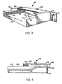
- a second embodiment of the invention may be seen as designated generally by the numeral 40.
- the note receptacle 40 includes a back plate 42 having holes 44 therein for securing engagement with the slot acceptor. Tines 46 are also provided for proper secured alignment between the receptacle 40 and the validator slot.
- a passage 48 is defined between an upper plate 50 and a lower plate 52, the lower plate 52 having an arcuate inclined portion beneath the front edge of the top plate 50.
- Side rails 54 define the width of the bottom plate 52, which plate is adapted for receiving papers of a narrow width.
- side rails 56 are provided in engagment with the top plate 50 for defining a passage for wider notes or pieces of currency.
- the top portion 58 of the side rails 54 helps to define a track for such wider pieces of currency, the track 58 leading directly into the top surface of the lower plate 52, as best illustrated in Fig. 4. Again, the leading edge of the side rails 56 may be tapered as at 60 to facilitate insertion and reception of the currency being tendered.
- a narrow note may be placed between the side rails 54, moved upwardly across the inclined portion of the bottom plate 52, and through the passage 48 for registered reception by the slot acceptor.
- a wider note may be placed on the tracks 58, between the side rails 56 and tendered to the passage 48 for registered receipt by the slot acceptor.
- the passages 18, 48 have plural widths at the point of entry of the notes into the receptacles 10, 40 for registered receipt of notes of various widths.
- the passages 18, 48 are of a single width at the ends thereof where the notes leave the passages to enter the slot acceptor for validation. At this end, however, the notes are properly aligned for transport into a validation area.
- the receptacles 10,40 provide means for adapting a universal slot acceptor to receive currency and the like of various widths by simple application of the receptacle adapters disclosed herein. With the main structure of the universal slot acceptor remaining constant, the acceptor may be adapted for use in virtually any country by the implementation of software programming and the application of an appropriate receptacle adapter 10, 40.
- the invention allows the-presentation of at least two distinct widths of notes or pieces of currency to a slot acceptor-type of currency validator, with both widths being received by the validator in fixed, predetermined registration for testing. While only the best mode and preferred embodiments of the invention have been presented and described in detail, it will be understood that the invention is not limited thereto or thereby. Accordingly, for an appreciation of the true scope and breadth of the invention, reference should be had to the following claims.
Landscapes
- Physics & Mathematics (AREA)
- General Physics & Mathematics (AREA)
- Inspection Of Paper Currency And Valuable Securities (AREA)
Claims (10)
Applications Claiming Priority (2)
| Application Number | Priority Date | Filing Date | Title |
|---|---|---|---|
| US06/389,029 US4504052A (en) | 1982-06-16 | 1982-06-16 | Note receptacle for currency validator |
| US389029 | 1989-08-03 |
Publications (3)
| Publication Number | Publication Date |
|---|---|
| EP0099324A2 EP0099324A2 (de) | 1984-01-25 |
| EP0099324A3 EP0099324A3 (en) | 1987-04-01 |
| EP0099324B1 true EP0099324B1 (de) | 1990-02-07 |
Family
ID=23536535
Family Applications (1)
| Application Number | Title | Priority Date | Filing Date |
|---|---|---|---|
| EP83730054A Expired EP0099324B1 (de) | 1982-06-16 | 1983-06-14 | Annahmeeinrichtung für Banknotenprüfer |
Country Status (4)
| Country | Link |
|---|---|
| US (1) | US4504052A (de) |
| EP (1) | EP0099324B1 (de) |
| JP (1) | JPS593695A (de) |
| DE (1) | DE3381212D1 (de) |
Families Citing this family (14)
| Publication number | Priority date | Publication date | Assignee | Title |
|---|---|---|---|---|
| US4659073A (en) * | 1983-11-11 | 1987-04-21 | Gtech Corporation | Data reading apparatus |
| US4765607A (en) * | 1985-03-08 | 1988-08-23 | Mars, Incorporated | Stacker apparatus |
| US5411249A (en) * | 1994-01-10 | 1995-05-02 | Mars Incorporated | Currency validator and cassette transport alignment apparatus |
| US5405131A (en) * | 1994-01-10 | 1995-04-11 | Mars Incorporated | Currency validator and secure lockable removable currency cassette |
| US6293469B1 (en) | 1994-12-20 | 2001-09-25 | Dh Technology Inc. | Transaction printer |
| US5632367A (en) * | 1995-01-23 | 1997-05-27 | Mars, Incorporated | Validation housing for a bill validator made by a two shot molding process |
| US5616915A (en) * | 1995-01-23 | 1997-04-01 | Mars Incorporated | Optical sensor for monitoring the status of a bill magazine in a bill validator |
| US5737418A (en) * | 1995-05-30 | 1998-04-07 | International Game Technology | Encryption of bill validation data |
| US5547062A (en) * | 1995-05-31 | 1996-08-20 | Diversified Technologies, Inc. | Universal currency acceptor |
| US5791449A (en) * | 1996-05-30 | 1998-08-11 | Mars Incorporated | Bezel for a vending machine |
| JP4281085B2 (ja) * | 2003-05-21 | 2009-06-17 | 株式会社日本コンラックス | 紙幣処理装置 |
| JP2005122427A (ja) * | 2003-10-16 | 2005-05-12 | Matsushita Electric Ind Co Ltd | 紙幣識別装置 |
| WO2008112532A1 (en) * | 2007-03-09 | 2008-09-18 | Digital Business Processes, Inc. | Scanner having a slot assembly for multiple-sized sheets |
| WO2016075696A1 (en) | 2014-11-13 | 2016-05-19 | Corning Optical Communications Wireless Ltd. | Analog distributed antenna systems (dass) supporting distribution of digital communications signals interfaced from a digital signal source and analog radio frequency (rf) communications signals |
Family Cites Families (9)
| Publication number | Priority date | Publication date | Assignee | Title |
|---|---|---|---|---|
| US593003A (en) * | 1897-11-02 | Paper-bag cabinet | ||
| US1241897A (en) * | 1917-04-04 | 1917-10-02 | John H Ananson | Paper-holder. |
| FR1603650A (de) * | 1968-03-01 | 1971-05-10 | ||
| US3947015A (en) * | 1971-06-10 | 1976-03-30 | R. Funk & Co., Inc. | Paper sheet feeders having multiple storage magazines |
| JPS5211142Y2 (de) * | 1972-06-05 | 1977-03-10 | ||
| JPS4923520U (de) * | 1972-06-05 | 1974-02-28 | ||
| GB1557462A (en) * | 1976-12-10 | 1979-12-12 | Emi Ltd | Tokens transport |
| US4301361A (en) * | 1980-05-30 | 1981-11-17 | Autotote, Ltd. | Document handling device providing channels for documents of two widths |
| JPS5794761A (en) * | 1980-12-04 | 1982-06-12 | Fuji Xerox Co Ltd | Controlling system for carrying paper |
-
1982
- 1982-06-16 US US06/389,029 patent/US4504052A/en not_active Expired - Lifetime
-
1983
- 1983-06-14 EP EP83730054A patent/EP0099324B1/de not_active Expired
- 1983-06-14 DE DE8383730054T patent/DE3381212D1/de not_active Expired - Lifetime
- 1983-06-16 JP JP58106844A patent/JPS593695A/ja active Pending
Also Published As
| Publication number | Publication date |
|---|---|
| DE3381212D1 (de) | 1990-03-15 |
| EP0099324A2 (de) | 1984-01-25 |
| JPS593695A (ja) | 1984-01-10 |
| US4504052A (en) | 1985-03-12 |
| EP0099324A3 (en) | 1987-04-01 |
Similar Documents
| Publication | Publication Date | Title |
|---|---|---|
| US4504052A (en) | Note receptacle for currency validator | |
| CA1199891A (en) | Apparatus for sorting and counting the number of the banknotes | |
| US6516998B2 (en) | Self-service terminal | |
| US4834230A (en) | Apparatus for discriminating paper money and stacking the same | |
| US5547062A (en) | Universal currency acceptor | |
| US7255338B2 (en) | Method and apparatus for processing sheet material | |
| US5381021A (en) | Sheet alignment device having a display for indicating a reason for rejecting the sheet | |
| JP2017084036A (ja) | 紙葉類処理装置及び仕切りカード | |
| EP0940777B1 (de) | Münzendiskriminierer | |
| JP2603874Y2 (ja) | 紙幣取扱装置 | |
| JPH0110694Y2 (de) | ||
| JP3469263B2 (ja) | 紙幣取扱装置 | |
| EP0822910B1 (de) | Papierübergabevorrichtung | |
| JP2020035499A (ja) | 紙葉類処理装置 | |
| JPH1125313A (ja) | 紙幣金種判別装置 | |
| JPS5847489Y2 (ja) | 紙幣選別機の紙幣通路開閉装置 | |
| JP3032680U (ja) | 印刷紙葉類の真贋判別装置 | |
| KR0170094B1 (ko) | 지폐식별기의 지폐식별장치 | |
| JPH067424Y2 (ja) | 貨幣鑑別装置 | |
| JPH021652Y2 (de) | ||
| HK1013644A (en) | Selective device for rectangular sheets of paper | |
| JPH1055466A (ja) | 双方向紙葉鑑別装置 | |
| JPH10149471A (ja) | 識別装置 | |
| CN104737212A (zh) | 纸币处理机的硬币误插入防止机构 | |
| KR19980014936A (ko) | 지폐식별기의 지폐식별방법 및 장치 |
Legal Events
| Date | Code | Title | Description |
|---|---|---|---|
| PUAI | Public reference made under article 153(3) epc to a published international application that has entered the european phase |
Free format text: ORIGINAL CODE: 0009012 |
|
| AK | Designated contracting states |
Designated state(s): DE GB SE |
|
| 17P | Request for examination filed |
Effective date: 19840627 |
|
| PUAL | Search report despatched |
Free format text: ORIGINAL CODE: 0009013 |
|
| AK | Designated contracting states |
Kind code of ref document: A3 Designated state(s): DE GB SE |
|
| 17Q | First examination report despatched |
Effective date: 19880928 |
|
| GRAA | (expected) grant |
Free format text: ORIGINAL CODE: 0009210 |
|
| AK | Designated contracting states |
Kind code of ref document: B1 Designated state(s): DE GB SE |
|
| REF | Corresponds to: |
Ref document number: 3381212 Country of ref document: DE Date of ref document: 19900315 |
|
| PLBI | Opposition filed |
Free format text: ORIGINAL CODE: 0009260 |
|
| 26 | Opposition filed |
Opponent name: LANDIS & GYR BETRIEBS AG Effective date: 19901009 |
|
| PLAB | Opposition data, opponent's data or that of the opponent's representative modified |
Free format text: ORIGINAL CODE: 0009299OPPO |
|
| R26 | Opposition filed (corrected) |
Opponent name: MARS, INCORPORATED Effective date: 19931009 |
|
| EAL | Se: european patent in force in sweden |
Ref document number: 83730054.0 |
|
| PLAB | Opposition data, opponent's data or that of the opponent's representative modified |
Free format text: ORIGINAL CODE: 0009299OPPO |
|
| PGFP | Annual fee paid to national office [announced via postgrant information from national office to epo] |
Ref country code: SE Payment date: 19950427 Year of fee payment: 13 Ref country code: GB Payment date: 19950427 Year of fee payment: 13 |
|
| PGFP | Annual fee paid to national office [announced via postgrant information from national office to epo] |
Ref country code: DE Payment date: 19950524 Year of fee payment: 13 |
|
| R26 | Opposition filed (corrected) |
Opponent name: MARS, INCORPORATED Effective date: 19901009 |
|
| RDAG | Patent revoked |
Free format text: ORIGINAL CODE: 0009271 |
|
| STAA | Information on the status of an ep patent application or granted ep patent |
Free format text: STATUS: PATENT REVOKED |
|
| 27W | Patent revoked |
Effective date: 19950921 |
|
| GBPR | Gb: patent revoked under art. 102 of the ep convention designating the uk as contracting state |
Free format text: 950921 |
|
| APAH | Appeal reference modified |
Free format text: ORIGINAL CODE: EPIDOSCREFNO |