EP0099376B1 - Structure d'etrier - Google Patents
Structure d'etrier Download PDFInfo
- Publication number
- EP0099376B1 EP0099376B1 EP83900396A EP83900396A EP0099376B1 EP 0099376 B1 EP0099376 B1 EP 0099376B1 EP 83900396 A EP83900396 A EP 83900396A EP 83900396 A EP83900396 A EP 83900396A EP 0099376 B1 EP0099376 B1 EP 0099376B1
- Authority
- EP
- European Patent Office
- Prior art keywords
- handle portion
- container
- edge
- portions
- anchor
- Prior art date
- Legal status (The legal status is an assumption and is not a legal conclusion. Google has not performed a legal analysis and makes no representation as to the accuracy of the status listed.)
- Expired
Links
Images

Classifications
-
- A—HUMAN NECESSITIES
- A45—HAND OR TRAVELLING ARTICLES
- A45F—TRAVELLING OR CAMP EQUIPMENT: SACKS OR PACKS CARRIED ON THE BODY
- A45F5/00—Holders or carriers for hand articles; Holders or carriers for use while travelling or camping
- A45F5/10—Handles for carrying purposes
-
- B—PERFORMING OPERATIONS; TRANSPORTING
- B65—CONVEYING; PACKING; STORING; HANDLING THIN OR FILAMENTARY MATERIAL
- B65D—CONTAINERS FOR STORAGE OR TRANSPORT OF ARTICLES OR MATERIALS, e.g. BAGS, BARRELS, BOTTLES, BOXES, CANS, CARTONS, CRATES, DRUMS, JARS, TANKS, HOPPERS, FORWARDING CONTAINERS; ACCESSORIES, CLOSURES, OR FITTINGS THEREFOR; PACKAGING ELEMENTS; PACKAGES
- B65D23/00—Details of bottles or jars not otherwise provided for
- B65D23/003—Suspension means
-
- B—PERFORMING OPERATIONS; TRANSPORTING
- B65—CONVEYING; PACKING; STORING; HANDLING THIN OR FILAMENTARY MATERIAL
- B65D—CONTAINERS FOR STORAGE OR TRANSPORT OF ARTICLES OR MATERIALS, e.g. BAGS, BARRELS, BOTTLES, BOXES, CANS, CARTONS, CRATES, DRUMS, JARS, TANKS, HOPPERS, FORWARDING CONTAINERS; ACCESSORIES, CLOSURES, OR FITTINGS THEREFOR; PACKAGING ELEMENTS; PACKAGES
- B65D25/00—Details of other kinds or types of rigid or semi-rigid containers
- B65D25/28—Handles
- B65D25/2867—Handles with respective ends fixed to local areas of two opposite sides or wall-part
- B65D25/2873—Straps or slings
- B65D25/2876—Straps or slings fixed by means of a collar
-
- G—PHYSICS
- G09—EDUCATION; CRYPTOGRAPHY; DISPLAY; ADVERTISING; SEALS
- G09F—DISPLAYING; ADVERTISING; SIGNS; LABELS OR NAME-PLATES; SEALS
- G09F3/00—Labels, tag tickets, or similar identification or indication means; Seals; Postage or like stamps
- G09F3/02—Forms or constructions
- G09F3/0295—Labels or tickets for tubes, pipes and the like
-
- G—PHYSICS
- G09—EDUCATION; CRYPTOGRAPHY; DISPLAY; ADVERTISING; SEALS
- G09F—DISPLAYING; ADVERTISING; SIGNS; LABELS OR NAME-PLATES; SEALS
- G09F3/00—Labels, tag tickets, or similar identification or indication means; Seals; Postage or like stamps
- G09F3/02—Forms or constructions
- G09F2003/027—Forms or constructions used to hang up an item, e.g. a perfusion bottle
Definitions
- the present invention relates to structures of flexible polymeric material that may be attached to containers to provide a bail or hanger for the container.
- Such prior art structures can provide some advantages over more conventional metal bail or hanger structures, which advantages may include ease of application, ease of labeling for the container to which they are attached, reduction or elimination of corrosion during storage, reduction of denting and scuffing of labels on containers packed together, and ease of color coding.
- U.S. Patent No. 3,623,633 and FR-A--2,098,415 described a bail structure which is an elongate strip of flexible material having end anchor portions adapted to be adhered circumferentially around the periphery of a container adjacent one of its ends, and a central handle portion adapted to extend between generally opposite locations on the periphery of the container when the anchors are adhered to the container.
- the handle portion can then be moved from a normal storage position extending circumferentially around the periphery of the container in alignment with its end portions, to a use position extending at right angles to its end portions and extending across the end of the container, at which use position the central portion may be used to carry or suspend the container.
- this elongate strip can be cut from sheet material and need not be molded or made to close tolerances, and can be applied without any substantial problems relating to the shape or tolerances of the container end, folds formed in the strip between its handle and anchor portions when its handle portion is moved to its use position tend to peel the adhesive attaching the anchor portions away from the container as tension is applied to the handle portion by supporting the weight of the container or otherwise, so that a special high shear adhesive is specified to restrict such peeling.
- the present invention provides a bail assembly that, like the bail assembly described in U.S. Patent No. 3,623,633 and FR-A-2,098,415 comprises an inexpensive, elongate, polymeric strip which can be cut from sheet material, and includes end anchor portions that can be easily bonded as by an adhesive to generally opposite sides of a container without any substantial problems relating to the shape of the container, and a central handle portion that then extends circumferentially around the side of the container in a storage position and can be moved to a use position across the end of a container; but which, unlike the bail assembly of U.S. Patent No. 3,623,633 and FR-A-2,098,415 does not place the bond or adhesive between the anchor portions and a container in peel when stress is applied to the handle portion in its use position.
- a container having an axis; and a bail structure attached to said container, said bail structure comprising:
- the anchor portions can be bonded on opposite sides of a container with the major surfaces of the strip generally parallel to an axis of the container and with the handle portion in a storage position adjacent an end of the container.
- the handle portion can then be moved to a use position extending across the end of the container at which use position the container may be suspended via the handle portion.
- the second part of the anchor portion resists the stresses that are applied in peel to the adhesive between the anchor portions and container in the structure described in U.S. Patent No. 3,623,633 and FR-A-2,098,415; and instead of peel, applies these stresses in shear to the bond or adhesive between the anchor portions and the container. This is advantageous since most bonds or adhesives have more strength in shear than in peel.
- the arcuate end portions of the second edge (which arcuate end portions extend away from the first edge generally at right angles to the longitudinal direction of the handle portion when the major surfaces of the handle and anchor portions are coplanar) provide means for greatly restricting the effects of notch sensitivity at the ends of the second edge when the handle portion is in its use position.
- notch sensitivity could otherwise facilitate tearing of the strip at the ends of the second edge and such tearing would result in the application of forces at the handle portion in peel to the bond or adhesive attaching the anchor portions to the container.
- Suitable polymeric materials for the strip material should be tear resistant, need not be oriented in any direction but preferably orient themselves slightly upon stretching to improve their tear resistance at the ends of the second edge, may be solid, woven or nonwoven construction and are preferably somewhat stretchable so that they tend to absorb shock loads applied at the handle portion.
- Suitable materials include polyurethanes, polybutylene, polypropylenes, and modified polyethylene ionomers such as that sold under the trade designation "Surlyn" by Dupont.
- the thickness of the materials may vary depending on the weight and use of the container to which the bail assembly is attached, however, materials having a thickness of about 12 mils appear suitable to support a gallon (3.8 litre) container filled with most materials.
- the anchor portions may be bonded through the use of an adhesive or by any other suitable method which may include heat sealing or sonic welding if the container is of a suitable material.
- the adhesives used for bonding the anchor portion may be any suitable thermoplastic or pressure-sensitive adhesive.
- pressure-sensitive adhesives When pressure-sensitive adhesives are used they may be adhered over one entire major surface of the strip material, and the adhesive on the handle portion of the bail structure may be detackified (e.g., by applying talcum powder) to prevent the handle portion from becoming adhered to a container, or may be covered by a cover sheet which both prevents the handle portion from becoming adhered to a container and thickens the handle portion so that it is more comfortable to grasp.
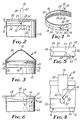
- FIG. 1 of the drawing there is shown a first embodiment of a bail structure according to the present invention generally designated by the reference numeral 10; which bail structure 10 is shown attached to a container or pail 12 of the type generally used to hold paint in Figures 2, 3 and 4 and is shown in Figure 7 attached to a container or bottle 14 of the type used to contain fluids adapted to be intravenously introduced into a patient.
- bail structure 10 is shown attached to a container or pail 12 of the type generally used to hold paint in Figures 2, 3 and 4 and is shown in Figure 7 attached to a container or bottle 14 of the type used to contain fluids adapted to be intravenously introduced into a patient.
- the bail structure 10 comprises a tough, flexible, elongate polymeric strip 16 including an elongate handle portion 18 having two opposite ends 20 and first and second opposite edges 22 and 24 respectively extending between its opposite ends 20, with the second edge 24 having arcuate end portions 25 at the ends 20 of the handle portion 18 extending away from the first edge 22 in a direction generally at right angles to the longitudinal direction of the handle portion 18, which arcuate end portions 25 define about 90 degree arcs of generally circular openings 27 through the strip at the juncture of the handle and anchor portions 18 and 26.
- anchor portions 26 are also included in the strip 16 .
- the anchor portions 26 are integrally formed with the handle portion 18 with one anchor portion 26 at each of its opposite ends 20.
- Each of the anchor portions 26 comprises first and second contiguous parts 30 and 32 shaped so that, when the major surfaces of the handle and anchor portion 18 and 26 are coplanar, the first part 30 projects away from the handle portion 18 in a direction generally aligned with the length of the handle portion 18; and the second part 32 projects away from the first part 30 along and past the adjacent arcuate end portion 25 of the second edge 24 in a direction generally normal to the length of the handle portion 18, and extends around the adjacent arcuate end portion 25 along the second edge 24 of the handle portion 18.
- the anchor portions 26 can be adhered on opposite sides of a container (e.g., pail 12 or bottle 14) via the adhesive layer 28 with the major surfaces of all portions of the strip 16 generally parallel to an axis of the container 12 or 14 and with the handle portion 18 in a storage position adjacent an end of the container 12 or 14 (solid lines in Figure 2). Subsequently the handle portion 18 can be moved to a use position (dotted lines in Figure 2 and solid lines in Figures 4 and 7) extending across the adjacent end of the container 12 or 14, at which use position the handle portion 18 may be used to suspend the container (e.g., used to manually carry the pail 12 or suspend the bottle 14 in an inverted position from a hanger).
- a container e.g., pail 12 or bottle 14
- the arcuate end portions 25 of the second edge 24 restrict tearing of the strip 16 at the second edge 24 when the container 12 or 14 is suspended by the handle portion 18. in the use position of the handle portion 18, the end portions 25 of the second edge 24 are somewhat straightened and extend generally axially along the container 12 or 14 and away from the handle portion 18 ( Figures 4 and 7) so that the end portions 25 of the second edge 24 are then generally parallel with the forces applied through the handle portion 18 to suspend the container 12 or 14 and there is little tendency for a tear to be initiated in the anchor portions 26 by the second edge 24.
- the bail structure 10 includes a cover sheet 42 over the adhesive layer 28 on the handle portion 18 which both prevents the adhesive layer 28 from adhering the handle portion 18 to the side of the container 12 or 14, and thickens the handle portion 18 to provide a more comfortable grip for a person carrying the container by the handle portion 18.
- the bail structure 50 comprises a tough, flexible, elongate polymeric strip 51 incud- ing an elongate handle portion 52 having two opposite ends 53 and first and second opposite edges 54 and 55 respectively extending between its opposite ends 53, with the second edge 55 having arcuate end portions 59 at the ends 53 of the handle portion 52 extending away from the first edge 54 in a direction generally at right angles to the longitudinal direction of the handle portion 52; and two anchor portions 56 adapted to be bonded as by adhesive to a container.
- the anchor portions 56 are integrally formed with the handle portion 52 with one anchor portion 56 at each of its opposite ends 53.
- Each of the anchor portions 56 comprises first and second contiguous parts 57 and 58 shaped so that, when the major surfaces of the handle and anchor portion 52 and 56 are coplanar, the first part 57 projects away from the handle portion 52 in a direction generally aligned with the handle portion 52, and the second part 58 projects away from the first part 57 along and past the adjacent arcuate end portion 59 of the second edge 55 in a direction generally normal to the length of the handle portion 52, and extends around the adjacent arcuate terminal end 59 and along the second edge 55 of the handle portion 52.
- the anchor portions 56 can be bonded on generally opposite sides of a container via an adhesive with the major surfaces of all portions of the strip 51 generally parallel to an axis of the container and with its handle portion 52 in a storage position adjacent an end of the container, and subsequently the handle portion 52 can be moved to a use position extending across the adjacent end of the container, at which use position the handle portion 52 may be used to suspend the container.
- the arcuate end portions 59 of the second edge 55 restrict tearing of the strip 51 at the second edge 55 when the container is suspended by the handle portion 52.
- the end portions 59 of the second edge 55 are generally straightened and extend generally axially along the container and away from the handle portion 52, and are then generally parallel with the forces applied through the handle portion 52 to suspend the container so that there is little tendency for a tear to be initiated in the anchor portions 56 by the second edge 55.
- the handle portion 52 of the bail structure 50 is attached to the anchor portion 56 at locations 49 that initially hold the handle portion 52 in its storage position until a user ruptures the locations 49 to move the handle portion 52 to use position.
- FIG. 6 there is shown a third embodiment of a bail structure 60 according to the present invention which illustrates an alternate form of the bail structure 10 which facilitates moving its handle portion from its storage position to its use position over a chime 61 on a container 62 that projects axially beyond the peripheral surface of the container 62.
- the bail structure 60 comprises a tough, flexible, elongate polymeric strip 63 including an elongate handle portion 64 having two opposite ends 65 and first and second opposite edges 66 and 67 respectively extending between its opposite ends 65, and two anchor portions (not shown) adapted to be bonded as by adhesive to the container 62.
- the anchor portions are integrally formed with the handle portion 64 with one anchor portion at each of its opposite ends 65, and could have the same structure as the anchor portion 26 or the anchor portion 56, thereby permitting the handle portion 64 to move between a storage position and a use position in the manner of the handle portions 18 and 52 as is described above.
- the bail structure 60 includes a cover sheet 68 over an adhesive layer on the handle portion 64.
- the bail structure 60 includes a tab 69 which is part of the cover sheet 68 and is located generally centrally along the length of the handle portion 64.
- the tab 69 projects generally normally away from the second edge 67 of the handle portion 64 and is adapted to be manually grasped to facilitate moving the handle portion from its storage to its use position extending across the end of the container 62.
- Thistab 69 is particularly useful where the bail structure is used on the type of container 62 shown in Figure 6 that has a projecting chime 61 rather than a recessed chime that has an outer surface flush with the outer surface of a container as is illustrated in the container 12 of Figures 2 and 3.
- the tab 69 provides added reinforcement for the central part of the handle portion 64 which may be desirable, particularly where that central part may be engaged over a narrow hook to support the container 62 to which the bail structure 60 is adhered.
- the handle portion 64 may have an undulating second edge 67 that produces a central part of the handle 64 portion that has a greater width and cross sectional area than parts of the handle portion 64 between its central part and its ends 65.
- the wider central part provides added reinforcement at the center of the handle portion 64 to restrict its rupture when it is engaged over a hook-like support, and the parts of the handle portion 64 of lesser cross sectional area between its central part and its ends 65 can stretch to absorb any exceptionally high stresses that may be applied to the handle portion 64 to restrict the application of stress at the ends 65 of central part of the handle portion 64that might otherwise cause their failure.
- FIG. 8 and 9 there is shown a fourth embodiment of a bail structure 70 according to the present invention which illustrates an alternate form of the handle portion 18 of the bail structure 10 which allows access under the handle portion in its use position when the bail structure 70 is used on a container 71 having an end that is semispherical in shape.
- the bail structure 70 comprises a tough, flexible, elongate polymeric strip 73 including an elongate handle portion 74 having two opposite ends 75 and first and second opposite edges 76 and 77 respectively extending between its opposite ends 75, and two anchor portions 78 adapted to be bonded as by an adhesive to the container 71.
- the anchor portions 78 are integrally formed with the handle portion 74 with one anchor portion 78 at each of its opposite ends 75, and could have the same structure as the anchor portion 26 or the anchor portion 56, thereby permitting the handle portion 74 to move between a storage position and a use position in the manner of the handle portions 18 and 52 as is described above.
- the handle portion 74 has an inner surface length that is longerthan the circumference of the container 71 between the locations at which the anchor portions 78 are bonded so that the handle portion 74 will project from the surface of the container 71 in both its storage and use positions to provide access to manually engage the handle portion 74 in its storage position, and to place a hook or other support under the handle portion 74 in its use position.
- anchor portions 78 in the bail structure 70 are not joined as in the other bail structures illustrated, which facilitates forming the bail structure 70.
- the anchor portions of the other bail structures illustrated need not be joined either, of course, if this would provide any advantage for the manufacture or application of those bail structures.
- the two elongate reinforcement members 81 in the embodiment 80 bridge from the handle portion 18a across its ends 20a onto its anchor portions 26a and may be useful to provide added strength in this area.
- the generally circular reinforcement members 91 in the embodiment 80 extend around the openings 27b to help reinforce the arcuate terminal ends 25b of the second edge 24b of the handle portion 18b where it joins the anchor portion 26b.
- Either of the reinforcement members 81 or 91 are made of a tough flexible polymeric material such as those listed above and can be adhered to the outer major surface, but are preferably adhered to the inner major surface of the strip 16a or 16b.
- the bail structure 100 comprises a tough, flexible, elongate polymeric strip 101 including the elongate handle portion 102 having two opposite ends 103 and first and second opposite edges 104 and 105 respectively extending between its opposite ends 103, with the second edge 105 having arcuate end portions 109 at the ends 103 of the handle portion 102 extending away from the first edge 104 in a direction generally at right angles to the longitudinal direction of the handle portion 102; and two anchor portions 106 adapted to be bonded as by an adhesive to a container.
- the anchor portions 106 are integrally formed with the handle portion 102 with one anchor portion 106 at each of its opposite ends 103.
- Each of the anchor portions 106 comprises first and second contiguous parts 107 and 108 shaped so that, when the major surfaces of the handle and anchor portion 102 and 106 are coplanar, the first part 107 projects away from the handle portion 102 in a direction generally aligned with the handle portion 102, and the second part 108 projects away from the first part 107 along and past the adjacent arcuate end portion 109 of the second edge 105 in a direction generally normal to the length of the handle portion 102.
- the anchor portions 106 can be bonded on opposite sides of a container with the major surfaces of all portions of the strip 101 generally parallel to an axis of the container and with its handle portion 102 in a storage position adjacent an end of the container, and subsequently the handle portion 102 can be moved to a use position extending across the adjacent end of the container, at which use position the handle portion 102 may be used to suspend the container.
- the arcuate end portions 109 of the second edge 105 restrict tearing of the strip 101 at the ends of the second edge 105 when the container is suspended by the handle portion 102.
- the end portions 109 of the second edge 105 are generally straightened so that they extend axially along the container and away from the handle portion 102 and are then generally parallel with the forces applied through the handle portion 102 to suspend the container so that there is little tendency for a tear to be initiated by the second edge 105.
- bail structure could be used to both bind together and carry a plurality of containers, rather than just a single container as illustrated; or that two or more bail structures could be used on a single container.
- the statement that the anchor portions can be or are bonded on opposite sides of a container includes positioning them so that a line through the ends of the handle portion will pass approximately through the central axis of the container causing the container to hang with its central axis generally vertically disposed below the handle portion; or, alternatively, positioning them so that a line through the ends of the handle portion will pass through the container on one side of its central axis so that the container will hang with its central axis disposed at an acute angle to the vertical direction, which may be desirable for some purposes and may provide less localized stresses at the ends of the handle portion where a line through the ends of the handle portion is spaced from the axis on the side of the container around which the handle portion extends when it is in its storage position.
- a pull structure such as a length of cardboard which contains advertising or pricing information, may be conveniently inserted between the handle portion and a container when the handle portion is in its storage position to both impart the information printed thereon, and facilitate moving the handle portion to its use position.
Landscapes
- Engineering & Computer Science (AREA)
- Mechanical Engineering (AREA)
- Physics & Mathematics (AREA)
- General Physics & Mathematics (AREA)
- Theoretical Computer Science (AREA)
- Details Of Rigid Or Semi-Rigid Containers (AREA)
- Massaging Devices (AREA)
- Magnetic Heads (AREA)
- Diaphragms For Electromechanical Transducers (AREA)
Abstract
Claims (8)
Applications Claiming Priority (2)
| Application Number | Priority Date | Filing Date | Title |
|---|---|---|---|
| US341903 | 1982-01-22 | ||
| US06/341,903 US4396128A (en) | 1982-01-22 | 1982-01-22 | Bail structure |
Publications (2)
| Publication Number | Publication Date |
|---|---|
| EP0099376A1 EP0099376A1 (fr) | 1984-02-01 |
| EP0099376B1 true EP0099376B1 (fr) | 1988-07-13 |
Family
ID=23339489
Family Applications (1)
| Application Number | Title | Priority Date | Filing Date |
|---|---|---|---|
| EP83900396A Expired EP0099376B1 (fr) | 1982-01-22 | 1982-12-20 | Structure d'etrier |
Country Status (7)
| Country | Link |
|---|---|
| US (1) | US4396128A (fr) |
| EP (1) | EP0099376B1 (fr) |
| JP (1) | JPS59500051A (fr) |
| AU (1) | AU555144B2 (fr) |
| CA (1) | CA1171005A (fr) |
| DE (1) | DE3278756D1 (fr) |
| WO (1) | WO1983002560A1 (fr) |
Families Citing this family (34)
| Publication number | Priority date | Publication date | Assignee | Title |
|---|---|---|---|---|
| GB8332216D0 (en) * | 1983-12-02 | 1984-01-11 | Metal Box Plc | Metal containers |
| DE3420114A1 (de) * | 1984-05-30 | 1985-12-05 | Bayer Ag, 5090 Leverkusen | Verfahren zur herstellung von uretdiongruppen aufweisenden polyisocyanaten |
| GB8424958D0 (en) * | 1984-10-03 | 1984-11-07 | Beecham Group Plc | Container |
| US4793647A (en) * | 1987-11-02 | 1988-12-27 | Marvin Claire C | Cup caddy |
| DE3907862A1 (de) * | 1989-03-10 | 1990-09-13 | Fresenius Ag | Ueber kopf aufzuhaengender behaelter mit einem etikett |
| US5135125A (en) * | 1991-02-15 | 1992-08-04 | Tapecon, Inc. | Hanging label |
| US5467915A (en) * | 1992-10-21 | 1995-11-21 | Roberts Systems, Inc. | Lift-up handle |
| US5318218A (en) * | 1992-10-21 | 1994-06-07 | Roberts Systems, Inc. | Latch for container |
| US5277359A (en) * | 1993-03-01 | 1994-01-11 | Church & Dwight Co., Inc. | Strap handle and package containing same |
| US5417365A (en) * | 1993-03-01 | 1995-05-23 | Church & Dwight Co., Inc. | Strap handle and package containing same |
| USD370845S (en) | 1993-04-21 | 1996-06-18 | Colgate-Palmolive Co. | Tamper evident cap |
| CA2112209A1 (fr) * | 1993-12-22 | 1995-06-23 | Carl Pomerantz | Languette volante adhesive |
| US5431334A (en) * | 1994-05-31 | 1995-07-11 | Roberts Systems, Inc. | Slide weld handle |
| GB9523030D0 (en) * | 1995-07-07 | 1996-01-10 | Creative Europ | A hanging device |
| US5738381A (en) * | 1995-09-25 | 1998-04-14 | Treleaven; Carl W. | Hanger label |
| US6349974B1 (en) | 1995-09-25 | 2002-02-26 | Pharmagraphics (Southeast), L.L.C. | Hanger label |
| US5782495A (en) * | 1996-01-11 | 1998-07-21 | Westlake Ventures, L.L.C. | Hanger label |
| US5951076A (en) * | 1998-01-28 | 1999-09-14 | Illinois Tool Works Inc. | Adhesive handle for enabling handling of a container, such as a bottle |
| US6457747B1 (en) | 1999-04-01 | 2002-10-01 | Pharmagraphics (Southeast) L.L.C. | Hanger label |
| US6296223B1 (en) | 1999-06-08 | 2001-10-02 | Pharmagraphics (Southeast) L.L.C. | Hanger label |
| US6361010B1 (en) | 1999-08-06 | 2002-03-26 | Pharmagraphics (Southeast), L.L.C. | Hanger label |
| ATE358637T1 (de) * | 2002-01-28 | 2007-04-15 | Coloplast As | Leicht zu öffnende verpackung |
| USD530147S1 (en) * | 2002-08-12 | 2006-10-17 | Senator Gmbh & Co. Kgaa | Bracket |
| DE10307250B4 (de) * | 2003-02-20 | 2007-05-16 | Schreiner Gmbh & Co Kg | Folienelement |
| WO2006000225A1 (fr) * | 2004-06-25 | 2006-01-05 | Simon Hem Jensen | Corps de recipient a anse integree |
| ATE380763T1 (de) * | 2004-12-13 | 2007-12-15 | Buelent Baylav | Ein schutzträger und handgriff für dosen |
| US20060255006A1 (en) * | 2005-05-16 | 2006-11-16 | Wagenknecht Samuel J | Universal fit bottle gripping appendage |
| US20070014958A1 (en) * | 2005-07-08 | 2007-01-18 | Chaplin Ernest R | Hanger labels, label assemblies and methods for forming the same |
| US9469455B2 (en) * | 2009-10-28 | 2016-10-18 | Kimberly-Clark Worldwide, Inc. | Discreet dual packaging |
| US9220372B2 (en) * | 2013-03-01 | 2015-12-29 | Whirlpool Corporation | Glass bowl assembly for bowl lift mixer |
| AU2015203850B1 (en) * | 2015-07-09 | 2016-01-28 | Matthew Scott Flatley | A carrying handle |
| US9457943B1 (en) * | 2016-04-15 | 2016-10-04 | Handi Foil Corporation | Bundling pans with a tape handle |
| US20180208380A1 (en) * | 2017-01-26 | 2018-07-26 | Dykam Ein Harod (Meuhad) Agricultural Cooperative Association Ltd. | Linerless Adhesive Carry Handle, Roll of Linerless Adhesive Carry Handles, and Method of Manufacture Thereof |
| US12190757B1 (en) * | 2024-04-16 | 2025-01-07 | Soho Brands Inc. | Label |
Family Cites Families (5)
| Publication number | Priority date | Publication date | Assignee | Title |
|---|---|---|---|---|
| US3623633A (en) * | 1970-04-20 | 1971-11-30 | Nat Can Corp | Flexible handle for containers and method of producing container handles |
| US3737069A (en) * | 1970-07-15 | 1973-06-05 | Illinois Tool Works | Container carrier with integral handle loop |
| US3717277A (en) * | 1970-11-23 | 1973-02-20 | Owens Illinois Inc | Handle for suspending intravenous solution bottles |
| US4022416A (en) * | 1975-10-29 | 1977-05-10 | W. G. Whitney Corporation | Plastic band and bail system for intravenous solution bottles |
| US4269322A (en) * | 1979-04-03 | 1981-05-26 | Minnesota Mining And Manufacturing Company | Flexible bail assembly |
-
1982
- 1982-01-22 US US06/341,903 patent/US4396128A/en not_active Expired - Lifetime
- 1982-12-20 AU AU11513/83A patent/AU555144B2/en not_active Expired
- 1982-12-20 EP EP83900396A patent/EP0099376B1/fr not_active Expired
- 1982-12-20 WO PCT/US1982/001775 patent/WO1983002560A1/fr not_active Ceased
- 1982-12-20 JP JP83500510A patent/JPS59500051A/ja active Pending
- 1982-12-20 DE DE8383900396T patent/DE3278756D1/de not_active Expired
- 1982-12-24 CA CA000418620A patent/CA1171005A/fr not_active Expired
Also Published As
| Publication number | Publication date |
|---|---|
| DE3278756D1 (en) | 1988-08-18 |
| CA1171005A (fr) | 1984-07-17 |
| JPS59500051A (ja) | 1984-01-12 |
| AU1151383A (en) | 1983-08-12 |
| US4396128A (en) | 1983-08-02 |
| WO1983002560A1 (fr) | 1983-08-04 |
| AU555144B2 (en) | 1986-09-11 |
| EP0099376A1 (fr) | 1984-02-01 |
Similar Documents
| Publication | Publication Date | Title |
|---|---|---|
| US4396128A (en) | Bail structure | |
| US6176615B1 (en) | Side-folded bag or sack | |
| US5120138A (en) | Flexible bag closure system | |
| US6698928B2 (en) | Flexible packages having reusable pull-tab openers | |
| US3815810A (en) | Opening and re-sealing device for bag containers | |
| US4324343A (en) | Folded tab | |
| US4167234A (en) | Self-storing container opening dispensing tape | |
| US6558789B1 (en) | Removable tape laminate including a flexible non-stretchable support layer | |
| WO2003059776A1 (fr) | Etiquette adhesive, emballage refermable et feuille d'etiquettes | |
| JPH0772799A (ja) | 剥離可能な無剥離紙ラベル及びその屋根瓦葺状またはジグザグ状構成体 | |
| US4500011A (en) | Tape closure for a can end | |
| JP2004510655A (ja) | ロールトップ・バッグ構造 | |
| JPS5926443A (ja) | 容器端部閉鎖複合体 | |
| NZ249909A (en) | Bag formed from folded pleated sheet: pleats releasably adhered | |
| US5378515A (en) | Corner tab and method of making same | |
| US4577777A (en) | Tape closure for a can end | |
| US4564121A (en) | Tape closure for a can end | |
| US3358873A (en) | Containers with opening means | |
| US20030042260A1 (en) | Method and apparatus to secure a reinforced flexible material about the open end of a container | |
| JPH0312680Y2 (fr) | ||
| JPH0123988Y2 (fr) | ||
| EP0113698B1 (fr) | Dispositif d'obturation par languette souple d'une extrémité de récipient | |
| CA3146457A1 (fr) | Attache biodegradable | |
| JPH07206010A (ja) | 易引裂性包装袋 | |
| CN214932306U (zh) | 一种饲料包装袋 |
Legal Events
| Date | Code | Title | Description |
|---|---|---|---|
| PUAI | Public reference made under article 153(3) epc to a published international application that has entered the european phase |
Free format text: ORIGINAL CODE: 0009012 |
|
| AK | Designated contracting states |
Designated state(s): DE FR GB SE |
|
| 17P | Request for examination filed |
Effective date: 19840125 |
|
| RBV | Designated contracting states (corrected) |
Designated state(s): DE FR GB SE |
|
| GRAA | (expected) grant |
Free format text: ORIGINAL CODE: 0009210 |
|
| AK | Designated contracting states |
Kind code of ref document: B1 Designated state(s): DE FR GB SE |
|
| REF | Corresponds to: |
Ref document number: 3278756 Country of ref document: DE Date of ref document: 19880818 |
|
| ET | Fr: translation filed | ||
| PLBE | No opposition filed within time limit |
Free format text: ORIGINAL CODE: 0009261 |
|
| STAA | Information on the status of an ep patent application or granted ep patent |
Free format text: STATUS: NO OPPOSITION FILED WITHIN TIME LIMIT |
|
| 26N | No opposition filed | ||
| EAL | Se: european patent in force in sweden |
Ref document number: 83900396.9 |
|
| PGFP | Annual fee paid to national office [announced via postgrant information from national office to epo] |
Ref country code: DE Payment date: 19991221 Year of fee payment: 18 |
|
| REG | Reference to a national code |
Ref country code: FR Ref legal event code: ST |
|
| PG25 | Lapsed in a contracting state [announced via postgrant information from national office to epo] |
Ref country code: DE Free format text: LAPSE BECAUSE OF NON-PAYMENT OF DUE FEES Effective date: 20011002 |
|
| PGFP | Annual fee paid to national office [announced via postgrant information from national office to epo] |
Ref country code: FR Payment date: 20011217 Year of fee payment: 20 |
|
| PGFP | Annual fee paid to national office [announced via postgrant information from national office to epo] |
Ref country code: GB Payment date: 20011221 Year of fee payment: 20 |
|
| PGFP | Annual fee paid to national office [announced via postgrant information from national office to epo] |
Ref country code: SE Payment date: 20011227 Year of fee payment: 20 |
|
| REG | Reference to a national code |
Ref country code: GB Ref legal event code: IF02 |
|
| REG | Reference to a national code |
Ref country code: FR Ref legal event code: RN |
|
| REG | Reference to a national code |
Ref country code: FR Ref legal event code: FC |
|
| PG25 | Lapsed in a contracting state [announced via postgrant information from national office to epo] |
Ref country code: GB Free format text: LAPSE BECAUSE OF EXPIRATION OF PROTECTION Effective date: 20021219 |
|
| REG | Reference to a national code |
Ref country code: GB Ref legal event code: PE20 Effective date: 20021219 |
|
| EUG | Se: european patent has lapsed |