EP0099412B1 - Verdichter - Google Patents
Verdichter Download PDFInfo
- Publication number
- EP0099412B1 EP0099412B1 EP82903340A EP82903340A EP0099412B1 EP 0099412 B1 EP0099412 B1 EP 0099412B1 EP 82903340 A EP82903340 A EP 82903340A EP 82903340 A EP82903340 A EP 82903340A EP 0099412 B1 EP0099412 B1 EP 0099412B1
- Authority
- EP
- European Patent Office
- Prior art keywords
- suction
- vane
- compressor
- cylinder
- rotor
- Prior art date
- Legal status (The legal status is an assumption and is not a legal conclusion. Google has not performed a legal analysis and makes no representation as to the accuracy of the status listed.)
- Expired
Links
Images








Classifications
-
- F—MECHANICAL ENGINEERING; LIGHTING; HEATING; WEAPONS; BLASTING
- F04—POSITIVE - DISPLACEMENT MACHINES FOR LIQUIDS; PUMPS FOR LIQUIDS OR ELASTIC FLUIDS
- F04C—ROTARY-PISTON, OR OSCILLATING-PISTON, POSITIVE-DISPLACEMENT MACHINES FOR LIQUIDS; ROTARY-PISTON, OR OSCILLATING-PISTON, POSITIVE-DISPLACEMENT PUMPS
- F04C28/00—Control of, monitoring of, or safety arrangements for, pumps or pumping installations specially adapted for elastic fluids
- F04C28/18—Control of, monitoring of, or safety arrangements for, pumps or pumping installations specially adapted for elastic fluids characterised by varying the volume of the working chamber
Definitions
- the present invention relates to a compressor in which refrigerative ability is restrained during high speed driving by utilizing the suction loss which occurs during the suction stroke when vane chamber pressure drops below the supply pressure of the source of refrigerant.
- Generally sliding vane type compressors comprise, as shown in Fig. 1, a cylinder 1 having a hollow interior defining a cylindrical space, side plates (not shown in Fig. 1) which are fixed to and close off both ends of the cylinder to define a vane chamber 2 inside the cylinder, a rotor 3 arranged accentrically within the cylinder 1, and vanes 5 slidably engaged with grooves 54 provided on the rotor 3. Further, there is a suction port 6 formed on one of the side plates and a discharge port 7 formed on cylinder 1. The vanes 5 slide outward under the action of the centrifugal force that accompanies rotation of the rotor 3, and the tips of the vanes slide on the interior surface of the cylinder to prevent leakage of the gas in the compressor.
- the driving force of the engine is transmitted to a pulley of a clutch through a belt, and it drives a rotary shaft of the compressor. Accordingly, when the sliding vane type compressor is used, its refrigerative ability rises in direct proportion to the rotational frequency of the vehicle engine.
- the present invention relates to improvements in said proposal, and it provides a fundamental construction to give. more effective control of the refrigerative ability of a compressor having many vanes (e.g. in a three-vane or four-vane type compressors).
- a compressor having vanes is preferable.
- the present invention provides a construction as defined in claim 1 which avoids said problems, and succeeds in gaining the ability to control refrigerative characteristics without any inferiority compared with e.g. two vane compressors by arranging at least two suction ports so that refrigerant flowing into adjacent individual vane chambers is supplied from each suction port mutually independently.
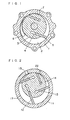
- Fig. 2 is a front sectional view of compressor showing an embodiment of the present invention
- 11 is a cylinder
- 12 vanes 13 sliding grooves of vanes
- 14 a rotor
- 15 a suction port A
- 17 a suction port B
- 22 is a discharging hole.
- Vane chamber as interior space of cylinder is closed tightly by side plates at side faces of cylinder.
- FIG. 3 18a is a vane chamber A, 18b a vane chamber B, 18c a vane chamber C, 19a top part of cylinder 11, 20a a vane A, and 20b is a vane B.
- Fig. 3(a) shows a state at time just after vane A20a has passed through top part 19.
- Fig. 3(b) shows a state when vane A20a lies at intermediate position between suction port A15 and suction port B17, and at this time, refrigerant is supplied into vane chamber A18a only from suction port A15.
- Fig. 3(c) shows a state when vane A20a has passed through suction port 17, and at the same time, vane B20b which travels following to vane A20a is passing through suction port A15.
- suction effective area of suction stream passage from supply source of refrigerant to vane chamber A18a is always constant during suction stroke.
- Fig. 3(d) shows a state in which refrigerant is supplied vane chamber A18a from only suction port B17.
- Fig. 3(e) shows a state at time just after vane B20b has passed through suction port B17, and since supply of refrigerant from suction port B17 is intercepted by vane B20b, suction stroke is finished at this time.
- vane chamber A18a, B18b, C18c can suck in refrigerant from said either two suction ports independently without intervening mutually.
- compressor in an embodiment of the present invention has been constituted under following condition. (The rest is blank).
- a compressor with ability control can be realized without losing any characteristic of rotary type compressor capable of compact, lightweight and simple constitution.
- suction pressure is lower and specific weight is smaller, total weight of refrigerant in vane chamber is smaller and compressing work is smaller. Accordingly, in this compressor in which decreasing in total weight of refrigerant is brought automatically at time just before compression stroke with increasing in numbers of rotation, at high speed rotation time, dropping in driving torque is brought inevitably.
- a compressor comprising the present invention
- ability control can be performed without performing useless machine work as causing said compression loss, and refrigerative cycle of energy-saving and high efficiency can be realized.
- the present invention as described in the following, has such a characteristic that transitional phenomena in vane chamber pressure is utilized effectively by suitable combination of each parameter of compressor, and having no operating part such as control valve. Therefore, it has high reliability.
- characteristic of the present invention lies in the fact that ability control character is gained effectively even in a compressor having many numbers of vane, e.g. in a four-vane type compressor of this embodiment.
- compressor of the present invention shown in Fig. 2
- customary compressors shown in Fig. 5 and Fig. 9 are selected as objects of analysis.
- 100 is a cylinder, 101 a suction port, 102 a vane chamber A, 103 a vane chamber C, 104 a vane A, 105 a suction groove, 106 a vane B, and 107 is a vane chamber B.
- Fig. 5(a) shows a state at time just after vane A104 has passed top part 108 of cylinder 100, and suction stroke has started.
- Fig. 5(b) shows a state when vane A104 is passing over suction groove 105, and at this time, refrigerant is supplied to vane chamber A102 from suction port 101, and at the same time, it also flows into the vane chamber C103 through suction groove 105.
- Fig. 5(c) shows a state when vane B106 which travels following to vane A104 is traveling through suction groove 105, and at this time, refrigerant is supplied to vane chamber A102 from only suction groove 105.
- vane chamber B107 is made as upstream side vane chamber
- vane chamber A102 is made as downstream side vane chamber,and noting to vane chamber B107
- equilibrium formula of energy is applied as follows:
- First term of formula (1) is energy
- second term is work made for exterior
- third term is total heat energy of refrigerant flowing into and discharging out of vane chamber
- fourth term is heat energy flowing into vane chamber through outer wall, and respectively shows a minute increment in minute time.
- first term of right side is total heat energy of refrigerant flowing into upstream side vane chamber from supply source of refrigerant
- second term of right side shows total heat energy of refrigerant discharging from upstream side vane chamber to downstream side vane chamber.
- i 1 C p T A
- i 2 C p T 1
- C P -C v AR when assuming that suction stroke of compressor is adiavatic change i.e.
- Cp constant-pressure specific heat
- C v constant-volume specific heat
- R gas constant
- K specific heat ratio
- T A refrigerant temperature at supply side
- G o total weight of vane chamber refrigerant
- P s supply pressure
- P 1 vane chamber pressure at upstream side
- T 1 vane chamber temperature at upstream side
- V 1 vane chamber volume at upstream side
- P 2 vane chamber pressure at downstream side
- T 2 vane chamber temperature at downstream side
- V 2 vane chamber volume at downstream side
- G 1 flow-rate in weight of refrigerant flowing into upstream side vane chamber through suction port 101
- G 2 flow-rate in weight of refrigerant flowing into downstream side vane chamber from upstream side through cylinder groove
- a 1 effective area of suction port 101
- a 2 effective area of cylinder groove
- YA specific weight of refrigerant at supply side
- Y 1 specific weight of refrigerant at supply side
- Y 1 specific weight of refrigerant at supply side
- pressure dropping rate ( ⁇ p ) is defined as follows: wherein,
- Graphs of solid line shows the case of compressor A, and graphs of chain line shows an embodiment of the present invention.
- Fig. 7 shows a character in pressure dropping rate when effective area (a 1 ) of suction port 101 is varied while effective area (a 2 ) of suction groove (a 2 ) is maintained constantly. At high speed, such a tendency is seen that as a 1 is larger, decreasing in pressure dropping rate ( ⁇ p) becomes smaller, but it has little effect to decrease pressure loss at low speed rotation.
- Fig. 4(a), (b) show practically measured results in compressor A using a calorie meter.
- Fig. 9 shows a constitution of compressor B in which suction port is formed on side plate, and 200 is cylinder, 201 a suction port formed on side plate (not shown), 203 upper vane chamber, 204 lower vane chamber, 205 rotor and 206 is vanes.
- opening area of stream passage at supply side communicated with suction port 201 is assumed to be large sufficiently. Assuming that refrigerative ability at supply side is constant always without affected by vane chamber pressure, as basic formulas denoted vane chamber pressure, one energy equation correspond to one formula of nozzle.
- Fig. 10 shows obtained suction effective area during suction stroke
- suction area (a) shows a case where opening area of suction port 201 formed on side plate is formed sufficiently largely
- suction area (b) shows a case where suction area is throttled at time just before finishing of suction stroke (194° ⁇ 6 ⁇ 225°).
- suction area (a) As may be seen from Fig. 11, suction loss at low speed time can be made small, but at high speed time, little pressure drop is produced. Accordingly, in this constitution, function of ability control can be gained scarcely.
- suction effective area has been varied into tapered pattern at time just before finishing of suction stroke i.e. when vane 206 traverses suction port 201.
- ability control character become inferior state.
- Fig. 4(a), (b) show measured results by calorie meter for compressor B comprising this constitution, and it may be seen that conditions required for ability control is scarcely satisfied similarly to compressor A.
- Characteristic of the present invention resides in an aspect that two chambers (e.q. 18a and 18b in Fig. 3) intercepted by a vane, by constitution of compressor where two or more suction ports are installed, are supplied with refrigerant from each suction port independently, without mutual intervention. Accordingly, in the basic formulas denoting chamber pressure, one energy equation correspond to one nozzle (suction port), thus model of one dimension as shown at electric circuit model in Table 3 is formed.
- Fig. 12 shows a two-vane type compressor as a reference.
- 300 is rotor, 301 cylinder, 302 vane A, 303 vane B, 304 a suction port, 305 a suction groove, 306 an end part of suction groove, 308 downstream side vane chamber, and 309 is upstream side vane chamber.
- a state is shown where vane B303 traveling followed to vane A302 has reached to end part 306 of suction groove, and supply of refrigerant into vane chamber A308 is intercepted and suction stroke has finished.
- model of one dimension of compressor C in Table 3 is formed approximately, and by proper selection of parameter in compressor, ideal ability control character can be gained.
- volume of vane chamber (V a ) is a function of rotor diameter (Rr), cylinder shape etc., but formulas (8), (9) and (10) are put in order using an approximate function, and a method to grasp correlation between each parameter and ability control effect is proposed.
- ⁇ varies from 0 to n
- volume (V a ) is denoted as follows:
- V o and f( ⁇ ) are function of Rr and Rc, but f( ⁇ ) varies very little by Rr and Rc.
- formula (8) becomes:
- formula (9) becomes: From formula (13) and (14):
- K becomes a non-dimensional quantity
- specific heat ratio ( K ) is a constant decided only by kind of refrigerant.
- suction effective area becomes a stepped variation as shown in Fig. 14(b).
- suction loss is decreased, and low torque may be intended at low speed.
- Fig. 15 shows a constitution of compressor when one of two suction ports is formed on side plate.
- 400 is rotor, 401 cylinder, 402 vanes, 403 a suction port A formed in cylinder 401 and 404 is a suction port B formed on side plate 405.
- each suction port 403 and 404 is formed similarly so that changeover of two suction ports are performed during suction stroke, and also so that supply of refrigerant into vane chamber is intercepted at finishing time of suction stroke due to covering by vane 402.
- Fig. 16 shows a case in which a suction groove is formed beside suction port A, and a section where refrigerant being supplied from both suction ports A, B is constituted.
- 450 is rotor, 451 cylinder, 452 vanes, 453 a suction port A, 454 a suction groove, 455 a suction port B, 456 a vane chamber A, and 457 is a vane chamber B.
- FIG. 16(a) refrigerant is supplied into vane chamber A456 from both suction port A453 and suction port B455.
- Fig. 16(b) shows a state at time just before finishing of suction stroke at vane chamber A456, and refrigerant is supplied into vane chamber A456 only from suction port B455. Suction effective area during suction stroke in this case is shown by (c) in Fig. 14.
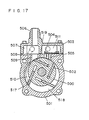
- Fig. 17 is a front sectional view of an embodiment showing concrete constitution of the present invention, and in the figure, 500 is rotor, 501 cylinder, 502 vanes, 503 a head cover, 504 a discharging valve, 504 a discharging hole, 506 a joint for suction piping, 507 a suction chamber formed between said cylinder 501 and inside of head cover 503, 508 shown by one dot chain line is a suction passage formed in rear case (not shown in Fig. 17), 509 is a suction port A communicating between said suction chamber 507 and vane chamber A501, 511 a vent chamber, 517 a suction port B, and 518 is a vane chamber B.
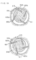
- Fig. 18 is an exploded view showing constitution of parts in this compressor, and 512 and 513 are rear case and rear plate as side plates, 514 a gasket, 515 a joint for discharging piping, and 516 is a communicating passage to communicate suction chamber 507 with suction stream passage.
- suction stream passage 508 is formed on rear plate 513 at side of gasket 514, supply of refrigerant from suction port A509 to vane chamber A510 is performed through such a course as suction piping joint 506 ⁇ suction chamber 507-suction port A509 ⁇ vane chamber A510.
- suction side and discharge side are constituted in separated state to left and right, at a boundary point formed by top part 519 of cylinder 501.
- vent chamber 511 accommodating discharging valve 504 and suction chamber 507 communicated with suction piping joint 506 can be constituted by head cover 503 of one body construction.
- suction piping joint may be one piece. Therefore, in this compressor, in spite of it has ability control function, simple and compact constitution is possible similarly to customary rotary type compressor.
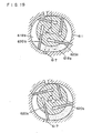
- Fig. 19 shows a compressor of this embodiment to make the present invention more effectively.
- This compressor aims to provide a compressor with ability control function in which loss in refrigerative ability at low speed is small, and restraining action in refrigerative ability at high speed can be gained more effectively by using such a cylinder shape that varying rate (minute) in volume curve of vane chamber in the neighborhood of finishing of suction stroke becomes more small compared with customary varying rate in volume curve.
- 611 is cylinder, 613 sliding grooves of vanes, 614 rotor, 615 a suction port A, 616 a suction groove, 617 a suction port B, and 622 is a discharging hole.
- FIG. 19(a)-(e) 618a is a vane chamber A, 618b a vane chamber B, 619a top part of cylinder 611, 620a a vane A, 620b a vane B, and 621 is an end part of suction groove.
- Fig. 19(a) show a state where vane A620a has passed through top part 619 and is traveling on suction groove 616.
- Fig. 19(b) shows a state where vane 620b following to vane A620a is traveling on suction groove 616, and in this case, refrigerant is supplied into vane chamber A618a through suction groove 616.
- effective area (a 2 ) of suction port A616 relative to effective area (a 1 ) of suction port A15 is made to be a 2 >>a 1 . Accordingly, suction effective area of stream passage communicating between vane chamber A618a and supply source of refrigerant, at state of Fig. 19(a), (b), is almost decided by effective area (a 1 ) of suction port A615.
- Fig. 19(c) shows a state at time just after vane A620a has passed through suction port B617, and at the same time, vane B620b has passed through end part 621 of suction groove 621.
- suction effective area of suction stream passage from supply source of refrigerant to vane chamber is always constant during suction stroke.
- Fig. 19(d) shows a state where traveling angle (8) of vane A620a has reached to a half of traveling angle during whole stroke (suction ⁇ compressing stroke).
- ⁇ traveling angle
- four vane type compressor constituted by true circular shape cylinder it becomes as ⁇ ⁇ s1 ⁇ 225°, and in this time, vane chamber volume becomes maximum.
- suction stroke is not finished yet, and refrigerant is supplied from suction port B617 to vane ⁇ chamber A618a as it was.
- Fig. 19(e) shows a state at time just after vane B620b has passed through suction port B617, and since supply of refrigerant from suction port B617 is intercepted by vane B620b, suction stroke finishes at this time.
- a cylinder shape which is formed from combination of two true circle and spaced by s between centers was used.
- O2 is center of left hand cylinder
- 0 3 is center of right hand cylinder
- center 0 1 of rotor 14 was arranged at equidistant point from said O2 and 0 3 .
- volume curve V a (8) of a vane chamber formed by said cylinder 611, rotor 614, vanes and side plates relative to vane traveling angle 8 became as curve (c) in Fig. 21 with parameter of spacing s.
- volume curve becomes nearly flat at range of 200° ⁇ 8 ⁇ 250°.
- compressor in one embodiment of the present invention was constituted under following condition.
- Fig. 22 shows refrigerative ability characters relative to numbers of rotation
- straight line (a) shows a character of customary rotary compressor without ability control effect
- curve (b) shows a character which has been gained already in said Patent Application
- curve (c) corresponds to a character of compressor in an embodiment of the present invention.
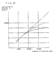
- characteristic of the present invention resides in a fact that it is noted to such a point that even if identical suction effective area is used, total suction weight of refrigerant differs by selection of volume curve of vane chamber, or by selection of cylinder shape.
- Fig. 26 shows pressure dropping rate relative to numbers of rotation by parameter of suction effective area obtained with a case of this embodiment, and a case of customary true circular cylinder.
- solid lines (aa-ff) show a case of customary true circular shaped cylinder.
- This embodiment can be applied to a compressor which has nearly elliptic shaped cylinder, and rotor is arranged at its center.
- cylinder shape of cylinder is formed as e.g. a function of sin28, and in order to apply the present invention, cylinder shape may be selected so that varying rate of volume curve nearly finishing of suction stroke becomes smaller compared with that of customary compressor similarly to a case of this embodiment, and it is more preferable if it can be made to have rough flat part.
- Fig. 27 shows its one example.
- 700 is a rotor circle around center 0 3 of radius Rr
- 701, 702, 703, 704 is a cylinder circle around center 0 1 , O2, 0 4 , 0 5 of radius Rc respectively.
- Distance e between centers 0 1 and O2, or 0 4 and O 5 may be small enough compared with dimensions such as Rr, Rc, and also, sufficiently far place from crossing point N of two circle may use other curve considering traveling stability of vane, etc.
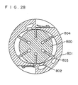
- Fig. 28 shows a forming method of suction port when the present invention is applied to a compressor having rough elliptic shaped cylinder.
- 800 is rotor, 801 cylinder, 802 a suction port A, 803 a suction port B, and 804 is vanes.
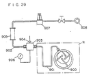
- Fig. 29 shows one example of this experimental method, and in the figure, 900 is compressor, 901 is a pipe to connect suction port of compressor with evaporator as compressor is mounted on car, 902 a high pressure air supplying pipe, 903 a housing to connect said both pipes 901 and 902, 904 a thermocouple, 905 a flow meter, 906 a pressure gauge, and 908 is a high pressure air source.
- a portion enclosed by one dot chain line (N) corresponds to a compressor as the object of this invention.
- a throttle corresponding to it must be added to said pipe 901.
- suction effective area (a) may be obtained by following formula:
- P 2 /P 1 is set so as to be within the range of 0.528 ⁇ P 2 /P 1 ⁇ 0.9. Further, it will be explained about relative position of suction port A15 and suction port B17 to be formed, with an example of compressor in which shape of inner face of cylinder 11 is true circle as shown in Fig. 2.
- ⁇ 2 is dividing angle between suction port A15 and suction port B17.
- a traveling section i.e. section of ⁇ 2
- the present invention constituted so that refrigerant is supplied into vane chamber from at least two or more suction ports during suction stroke, since elevation in volume efficiency can be intended at low speed rotation, it can be applied to a compressor in which ability control is unnecessary e.g. constant speed type compressor, thus the effect is remarkable.
Landscapes
- Engineering & Computer Science (AREA)
- Mechanical Engineering (AREA)
- General Engineering & Computer Science (AREA)
- Rotary Pumps (AREA)
Claims (6)
wobei die Ansaugöffnungen (15, 17) um den Umfang des Zylinders (11) derart verteilt angeordnnet sind, daß am Ende eines Ansaugtaktes die Flügelkammer mit Kühlmittel unabhängig von den benachbarten Flügelkammern gefüllt worden ist und der Parameter K22 im Bereich 0,025<K22<0,080 liegt.
Applications Claiming Priority (4)
| Application Number | Priority Date | Filing Date | Title |
|---|---|---|---|
| JP180814/81 | 1981-11-11 | ||
| JP56180814A JPS5882089A (ja) | 1981-11-11 | 1981-11-11 | ベ−ン形圧縮機 |
| JP57029719A JPS58144686A (ja) | 1982-02-24 | 1982-02-24 | 圧縮機 |
| JP29719/82 | 1982-02-24 |
Publications (3)
| Publication Number | Publication Date |
|---|---|
| EP0099412A1 EP0099412A1 (de) | 1984-02-01 |
| EP0099412A4 EP0099412A4 (de) | 1984-04-06 |
| EP0099412B1 true EP0099412B1 (de) | 1987-06-03 |
Family
ID=26367951
Family Applications (1)
| Application Number | Title | Priority Date | Filing Date |
|---|---|---|---|
| EP82903340A Expired EP0099412B1 (de) | 1981-11-11 | 1982-11-10 | Verdichter |
Country Status (4)
| Country | Link |
|---|---|
| US (1) | US4544337A (de) |
| EP (1) | EP0099412B1 (de) |
| DE (1) | DE3276489D1 (de) |
| WO (1) | WO1983001818A1 (de) |
Families Citing this family (10)
| Publication number | Priority date | Publication date | Assignee | Title |
|---|---|---|---|---|
| JPS5874891A (ja) * | 1981-10-28 | 1983-05-06 | Matsushita Electric Ind Co Ltd | ベ−ン形圧縮機 |
| GB2372324B (en) * | 2000-11-10 | 2004-12-22 | Leamount Ltd | Air flow measurement |
| GB0130717D0 (en) * | 2001-12-21 | 2002-02-06 | Wabco Automotive Uk Ltd | Vacuum pump |
| US6790019B1 (en) * | 2003-02-28 | 2004-09-14 | Thomas Industries Inc. | Rotary vane pump with multiple sound dampened inlet ports |
| US8123506B2 (en) | 2008-05-29 | 2012-02-28 | Flsmidth A/S | Rotary sliding vane compressor with a secondary compressed fluid inlet |
| RU2426899C2 (ru) * | 2008-11-05 | 2011-08-20 | Григорьянц Роберт Аветисович | Роторный двигатель внутреннего сгорания |
| US9267504B2 (en) | 2010-08-30 | 2016-02-23 | Hicor Technologies, Inc. | Compressor with liquid injection cooling |
| CA2809945C (en) | 2010-08-30 | 2018-10-16 | Oscomp Systems Inc. | Compressor with liquid injection cooling |
| JP2016513766A (ja) * | 2013-12-05 | 2016-05-16 | グアンドン メイジ コムプレッサ カンパニー リミテッド | ロータリ圧縮機及びその圧縮装置、エアコン |
| EP3617449B1 (de) * | 2019-12-12 | 2022-02-09 | Pfeiffer Vacuum Gmbh | Drehschiebervakuumpumpe |
Citations (4)
| Publication number | Priority date | Publication date | Assignee | Title |
|---|---|---|---|---|
| JPS5155411U (de) * | 1974-10-28 | 1976-04-28 | ||
| JPS5672283A (en) * | 1979-11-15 | 1981-06-16 | Daikin Ind Ltd | Multivane compressor |
| JPS5770986A (en) * | 1980-09-25 | 1982-05-01 | Matsushita Electric Ind Co Ltd | Compressor |
| EP0064356A1 (de) * | 1981-04-24 | 1982-11-10 | Matsushita Electric Industrial Co., Ltd. | Kompressor |
Family Cites Families (10)
| Publication number | Priority date | Publication date | Assignee | Title |
|---|---|---|---|---|
| FR538666A (fr) * | 1921-07-23 | 1922-06-13 | Perfectionnements apportés aux pompes, moteurs ou compteurs rotatifs | |
| CH133890A (de) * | 1928-06-05 | 1929-06-30 | Sulzer Ag | Drehkolbenmaschine. |
| US2361855A (en) * | 1941-05-28 | 1944-10-31 | Gen Motors Corp | Refrigerating apparatus |
| GB818691A (en) * | 1957-05-20 | 1959-08-19 | Lacy Hulbert & Company | Improvements in rotary air pumps |
| DE1287729B (de) * | 1961-10-19 | 1969-01-23 | ||
| US3182596A (en) * | 1963-05-31 | 1965-05-11 | Borg Warner | Hydraulic systems and pumps |
| DE2832247A1 (de) * | 1978-07-17 | 1980-01-31 | Riedl Geb Vossberg Leonore Ger | Schieberzellenverdichter mit unrundgehaeuse |
| US4299097A (en) * | 1980-06-16 | 1981-11-10 | The Rovac Corporation | Vane type compressor employing elliptical-circular profile |
| JPS57120792U (de) * | 1981-01-19 | 1982-07-27 | ||
| JPS57126590A (en) * | 1981-01-29 | 1982-08-06 | Matsushita Electric Ind Co Ltd | Compressor |
-
1982
- 1982-11-10 WO PCT/JP1982/000436 patent/WO1983001818A1/ja not_active Ceased
- 1982-11-10 US US06/522,366 patent/US4544337A/en not_active Expired - Lifetime
- 1982-11-10 DE DE8282903340T patent/DE3276489D1/de not_active Expired
- 1982-11-10 EP EP82903340A patent/EP0099412B1/de not_active Expired
Patent Citations (4)
| Publication number | Priority date | Publication date | Assignee | Title |
|---|---|---|---|---|
| JPS5155411U (de) * | 1974-10-28 | 1976-04-28 | ||
| JPS5672283A (en) * | 1979-11-15 | 1981-06-16 | Daikin Ind Ltd | Multivane compressor |
| JPS5770986A (en) * | 1980-09-25 | 1982-05-01 | Matsushita Electric Ind Co Ltd | Compressor |
| EP0064356A1 (de) * | 1981-04-24 | 1982-11-10 | Matsushita Electric Industrial Co., Ltd. | Kompressor |
Also Published As
| Publication number | Publication date |
|---|---|
| DE3276489D1 (en) | 1987-07-09 |
| US4544337A (en) | 1985-10-01 |
| EP0099412A1 (de) | 1984-02-01 |
| WO1983001818A1 (fr) | 1983-05-26 |
| EP0099412A4 (de) | 1984-04-06 |
Similar Documents
| Publication | Publication Date | Title |
|---|---|---|
| EP0059834B1 (de) | Verdichter mit Kühlleistungsregelung | |
| EP0099412B1 (de) | Verdichter | |
| CN100400884C (zh) | 可变容量的涡旋式压缩机 | |
| US3744942A (en) | Rotary sliding vane compressor with hydrostatic bearings | |
| US5090880A (en) | Scroll compressor with discharge valves | |
| US3723024A (en) | Reversible rotary compressor for refrigerators | |
| EP0049030B1 (de) | Drehkolben-Gleitflügelverdichter | |
| JPS60192892A (ja) | ベ−ン型圧縮機 | |
| US4737090A (en) | Movable vane compressor | |
| US3649140A (en) | Oil metering system for rotary compressor | |
| US5372489A (en) | Two stage vane type compressor | |
| US4702684A (en) | Slide vane type compressor with increased suction part-cross-sectional area | |
| US4696627A (en) | Scroll compressor | |
| EP0064356B1 (de) | Kompressor | |
| EP0101745B1 (de) | Rotierender verdichter | |
| EP0091968B1 (de) | Verdichter | |
| CN210290137U (zh) | 滑片式补气压缩机及空调器 | |
| US6872065B1 (en) | Vane gas compressor having two discharge passages with the same length | |
| CN215566600U (zh) | 离心式油气分离机构和二氧化碳压缩机 | |
| US4815945A (en) | Variable capacity vane compressor | |
| CN219220729U (zh) | 阀转接器、定涡旋组件、涡旋压缩机构和涡旋压缩机 | |
| CN108799115A (zh) | 变排量四缸双级压缩滚动转子压缩机 | |
| JPS6170191A (ja) | ベ−ン型圧縮機 | |
| JPH024792B2 (de) | ||
| CN118188495A (zh) | 阀转接器、定涡旋组件、涡旋压缩机构和涡旋压缩机 |
Legal Events
| Date | Code | Title | Description |
|---|---|---|---|
| PUAI | Public reference made under article 153(3) epc to a published international application that has entered the european phase |
Free format text: ORIGINAL CODE: 0009012 |
|
| 17P | Request for examination filed |
Effective date: 19830714 |
|
| AK | Designated contracting states |
Designated state(s): DE FR GB |
|
| GRAA | (expected) grant |
Free format text: ORIGINAL CODE: 0009210 |
|
| AK | Designated contracting states |
Kind code of ref document: B1 Designated state(s): DE FR GB |
|
| REF | Corresponds to: |
Ref document number: 3276489 Country of ref document: DE Date of ref document: 19870709 |
|
| ET | Fr: translation filed | ||
| PLBE | No opposition filed within time limit |
Free format text: ORIGINAL CODE: 0009261 |
|
| STAA | Information on the status of an ep patent application or granted ep patent |
Free format text: STATUS: NO OPPOSITION FILED WITHIN TIME LIMIT |
|
| 26N | No opposition filed | ||
| PGFP | Annual fee paid to national office [announced via postgrant information from national office to epo] |
Ref country code: GB Payment date: 19941101 Year of fee payment: 13 |
|
| PGFP | Annual fee paid to national office [announced via postgrant information from national office to epo] |
Ref country code: FR Payment date: 19941109 Year of fee payment: 13 |
|
| PGFP | Annual fee paid to national office [announced via postgrant information from national office to epo] |
Ref country code: DE Payment date: 19941110 Year of fee payment: 13 |
|
| PG25 | Lapsed in a contracting state [announced via postgrant information from national office to epo] |
Ref country code: GB Effective date: 19951110 |
|
| GBPC | Gb: european patent ceased through non-payment of renewal fee |
Effective date: 19951110 |
|
| PG25 | Lapsed in a contracting state [announced via postgrant information from national office to epo] |
Ref country code: FR Effective date: 19960731 |
|
| PG25 | Lapsed in a contracting state [announced via postgrant information from national office to epo] |
Ref country code: DE Effective date: 19960801 |
|
| REG | Reference to a national code |
Ref country code: FR Ref legal event code: ST |