EP0099513A2 - Assemblage d'échelons et montant pour une échelle en métal léger - Google Patents
Assemblage d'échelons et montant pour une échelle en métal léger Download PDFInfo
- Publication number
- EP0099513A2 EP0099513A2 EP83106596A EP83106596A EP0099513A2 EP 0099513 A2 EP0099513 A2 EP 0099513A2 EP 83106596 A EP83106596 A EP 83106596A EP 83106596 A EP83106596 A EP 83106596A EP 0099513 A2 EP0099513 A2 EP 0099513A2
- Authority
- EP
- European Patent Office
- Prior art keywords
- spar
- recesses
- profile
- connection
- leg
- Prior art date
- Legal status (The legal status is an assumption and is not a legal conclusion. Google has not performed a legal analysis and makes no representation as to the accuracy of the status listed.)
- Granted
Links
Images


Classifications
-
- E—FIXED CONSTRUCTIONS
- E06—DOORS, WINDOWS, SHUTTERS, OR ROLLER BLINDS IN GENERAL; LADDERS
- E06C—LADDERS
- E06C7/00—Component parts, supporting parts, or accessories
- E06C7/08—Special construction of longitudinal members, or rungs or other treads
Definitions
- the invention relates to a spar step connection in a light metal ladder according to the preamble of claim 1.
- connection between the spar and the step is made by riveting in the connection area of the spar and step.
- the disadvantage of this rivet connection is that the supporting cross-section of the spar is weakened by attaching the rivet holes and that the production of this rivet connection is relatively expensive and requires assembly. Own rivet feeding machines are required to feed the rivets to the assembly site for the connection.
- the invention has for its object to form a spar step connection of the type mentioned so that it is easier to manufacture and improved in strength.
- the invention is characterized in that the prebinding between the spar and tread consists of a latching connection with tabs of the spar which are latched into recesses in the tread.
- the spar has mutually opposing legs on the inside, which are punched out in the area of the treads in such a way that tabs remain. Have in the area of this rag the steps slits into which the spar engages with its rags. A lower edge on the bottom of the recess in the web area of the spar serves as additional support for the step.
- the assembly is done by a simple swiveling movement of the step opposite the spar.
- the step is bent in the elastic area and then springs back into its original shape after it has snapped into place.
- the tabs of the spar are pressed into the recesses after they have snapped into place and the recesses form closing heads which overlap on one side.
- the tabs are riveted after they have snapped into place, without the need for separate rivets.
- the spar consists of a mirror-symmetrical profile with respect to the longitudinal center axis, on the inner sides of which the legs are directed against one another and form longitudinal ribs, from the matorial of which the tabs divided by recesses are formed.
- the spar is thus made, for example, from an extruded aluminum profile and the ribs formed on the inside of the legs are consequently made of one piece of material with the rest of the spar profile.
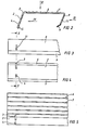
- the spar 10 consists of a U-extruded profile with an outwardly directed spar wall 18, and lateral legs 12, 13, on the inside of which opposing, opposing ribs 14, 15 are formed.
- the legs 12, 13 are continued downwards by cross-sections thickened by webs 16, 17.
- tabs 19, 24 are provided in the area of the ribs 14, 15, which lie opposite one another and which are formed by recesses 21, 22 (tab 19) or by recesses 25, 26 made of the material of the ribs 14, 15 are divided.
- the flaps 19, 24 lie diagonally opposite one another, the inclination resulting from the fact that, according to FIG. 1, the spar 10 itself is directed obliquely, so that the tread plane (step surface 6) of the step 1 to be fastened laterally is aligned horizontally.
- the edge of the rib 14 is not straight, but rather has an undercut 23, into which the thickened web 5 of the step 1 engages in the engaged state according to FIG. 1.
- edges of the recesses 22, 26 can be chamfered, as is shown in the example of the inclined surface 27 at the base of the recess 26 in FIG. 7.
- step 1 also consists of a U-shaped extruded profile, preferably of an aluminum material, just like the spar.
- the base leg is formed by the step surface 6, while the side legs 2, 8 are formed by mutually parallel, inclined surfaces.
- the leg 2 is continued at its free, lower end by a web 5 thickened cross-section, while the leg 8 has an inward bend 9 at its lower, free end.
- the upper recess 3 continues partially into the material of the step surface 6 of the step 1.
- FIG. 1 shows the latching connection between the step 1 and the spar 10 in the latched state, and in dashed lines shortly before reaching the latching position.
- the step 1 is placed with its recess 11 on the tab 24 of the spar 10 and pressed.
- the leg 8 deforms elastically inwards.
- the step 1 ' is then pivoted upwards in the direction of the arrow 28, so that on the one hand the tab 36 (FIG. 7) into the recess 3 engages and on the other hand the tab 19 in the recess 4 in the leg 2 of the step 1.
- the previously described inclined surface 27 is arranged in the region of the rib 15 on the inside of the spar 10.
- the flaps 19, 24 can then be processed with an upsetting tool, so that there is a closing head which extends beyond the recesses 3, 4, 11, so that the flaps 19, 24 are also made of one piece rivets connected to the profile of the spar can be addressed.
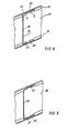
- FIG. 8 shows a second exemplary embodiment of a connection between a spar 30 and a step 20.
- a longer flap 24 according to FIG Engage recesses in the area of step 20.
- the engagement takes place in the direction of arrow 29.
- a tab 33 is provided which engages in the associated recess 2, while in the same way - as in FIG. 1 - there is a recess 3 in the area of the step 20 which is in a engages corresponding tab 36 of the spar 30, the tab 36 being formed by the profile of the rib 14.
- Figure 9 shows the riveted tabs 31 ', 32', 33 '.
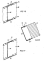
- FIGS. 10 to 12 show a third exemplary embodiment, it being evident that the one flap 33 according to the exemplary embodiment according to FIG. 8 is replaced by two mutually parallel flaps 34, 35, while the flap 24 according to the exemplary embodiment according to FIGS 7 was retained.
- the latching connection there between the step 40 and the spar 50 still has the special feature that instead of the flap 36, which is formed in one piece from the material of the web 14, the second flap 34 is present, and that there is one in the tread 7
- the recess 3 extending into the step is missing, and instead there is a recess provided only in the region of the leg of the step 40.
- FIG. 11 shows the riveted tabs 24 ', 34', 35'4
- FIG. 12 shows a section through the spar 50 in a plane parallel to the step surface 6 of the step 40, the section being cut through the tabs 34, 24 '.
Landscapes
- Engineering & Computer Science (AREA)
- Mechanical Engineering (AREA)
- Ladders (AREA)
- Joining Of Corner Units Of Frames Or Wings (AREA)
Priority Applications (1)
| Application Number | Priority Date | Filing Date | Title |
|---|---|---|---|
| AT83106596T ATE26152T1 (de) | 1982-07-22 | 1983-07-06 | Holm-stufenverbindung bei einer leichtmetallleiter. |
Applications Claiming Priority (2)
| Application Number | Priority Date | Filing Date | Title |
|---|---|---|---|
| DE3227363 | 1982-07-22 | ||
| DE19823227363 DE3227363A1 (de) | 1982-07-22 | 1982-07-22 | Holm-stufenverbindung bei einer leichtmetall-leiter |
Publications (3)
| Publication Number | Publication Date |
|---|---|
| EP0099513A2 true EP0099513A2 (fr) | 1984-02-01 |
| EP0099513A3 EP0099513A3 (en) | 1985-04-17 |
| EP0099513B1 EP0099513B1 (fr) | 1987-03-25 |
Family
ID=6169025
Family Applications (1)
| Application Number | Title | Priority Date | Filing Date |
|---|---|---|---|
| EP83106596A Expired EP0099513B1 (fr) | 1982-07-22 | 1983-07-06 | Assemblage d'échelons et montant pour une échelle en métal léger |
Country Status (3)
| Country | Link |
|---|---|
| EP (1) | EP0099513B1 (fr) |
| AT (1) | ATE26152T1 (fr) |
| DE (2) | DE3227363A1 (fr) |
Families Citing this family (1)
| Publication number | Priority date | Publication date | Assignee | Title |
|---|---|---|---|---|
| DE102024119469A1 (de) * | 2024-07-09 | 2026-01-15 | HYMER GmbH & Co. KG | Verbindungselement zum Aufbau eines T-förmigen Verbunds |
Family Cites Families (4)
| Publication number | Priority date | Publication date | Assignee | Title |
|---|---|---|---|---|
| DE2136640A1 (de) * | 1971-07-22 | 1973-02-01 | Fuchs Otto | Stufenleiter |
| DE2226213B2 (en) * | 1972-05-30 | 1975-04-03 | Walter 7120 Bissingen Kuemmerlin | Ladder rung to stringer fixture - has fillers detachably inserted in spaces between rung ends and cutout edges |
| DE2862162D1 (en) * | 1978-01-02 | 1983-02-24 | Cizely Fab Metall | Metal ladder |
| US4204587A (en) * | 1978-10-13 | 1980-05-27 | White Metal Rolling And Stamping Corp. | Ladder constructions |
-
1982
- 1982-07-22 DE DE19823227363 patent/DE3227363A1/de not_active Withdrawn
-
1983
- 1983-07-06 DE DE8383106596T patent/DE3370508D1/de not_active Expired
- 1983-07-06 EP EP83106596A patent/EP0099513B1/fr not_active Expired
- 1983-07-06 AT AT83106596T patent/ATE26152T1/de not_active IP Right Cessation
Also Published As
| Publication number | Publication date |
|---|---|
| EP0099513B1 (fr) | 1987-03-25 |
| DE3370508D1 (en) | 1987-04-30 |
| EP0099513A3 (en) | 1985-04-17 |
| DE3227363A1 (de) | 1984-01-26 |
| ATE26152T1 (de) | 1987-04-15 |
Similar Documents
| Publication | Publication Date | Title |
|---|---|---|
| DE60311774T2 (de) | Verbindungskonstruktion für längsträger an querträger | |
| DE2832118A1 (de) | Verbindungseinrichtung und mittels ihr erstelltes rahmen-tragwerk | |
| DE2925320A1 (de) | Verbindungsanordnung | |
| DE2827099C2 (de) | Gestanzter Beschlag zum Befestigen von Polsterfedern an Möbelartikeln | |
| DE10328042B4 (de) | Gleitschiene für einen Fahrzeugsitz | |
| DE3208749A1 (de) | Scheibenwischer | |
| DE2246065B2 (de) | Lattenrost | |
| EP0202510A2 (fr) | Chambranle ou cadre de battant pour fenêtres ou portes | |
| DE2935158C3 (de) | Stranggepreßtes Bauelement zum Aufbau von Wänden, insbesondere von Kraftfahrzeugen | |
| EP3303731B1 (fr) | Élément de plancher d'échafaudage, en particulier pour un échafaudage de construction | |
| DE2812128C3 (de) | Wärmeisolierender Profilkörper | |
| DE3027171C2 (de) | Metallbehälter | |
| DE3139287A1 (de) | "verbindungsplatte" | |
| EP0099513A2 (fr) | Assemblage d'échelons et montant pour une échelle en métal léger | |
| DE3115832C2 (de) | Verfahren zum Kürzen und Fertigstellen von Lamellen einer Vertikallamellenjalousie sowie hierfür geeignetes Haltemittel | |
| DE3152329C2 (de) | Fensterheber, insbesondere für Kraftfahrzeuge | |
| EP0280095A1 (fr) | Porte-récipients, en particulier pour bouteilles | |
| DE4026609C1 (en) | Casing for guide track telescopic covers - has each side wall with longitudinal slit on edge adjacent to front wall | |
| DE3539894A1 (de) | Verkleidung fuer bauwerke | |
| DE2448689C3 (de) | Scharnierarm aus Metallblech | |
| DE3512388A1 (de) | Regal | |
| DE3439782C2 (de) | Türflügel | |
| DE69203796T2 (de) | Verfahren zum Verbinden, durch Nieten, durch dieses Verfahren hergestellte Verbindung und Vorrichtung zum Herstellen. | |
| AT306335B (de) | Lamellenjalousie | |
| DE3326479C2 (de) | Brieflocher |
Legal Events
| Date | Code | Title | Description |
|---|---|---|---|
| PUAI | Public reference made under article 153(3) epc to a published international application that has entered the european phase |
Free format text: ORIGINAL CODE: 0009012 |
|
| AK | Designated contracting states |
Designated state(s): AT CH DE FR GB IT LI NL SE |
|
| 17P | Request for examination filed |
Effective date: 19840628 |
|
| PUAL | Search report despatched |
Free format text: ORIGINAL CODE: 0009013 |
|
| AK | Designated contracting states |
Designated state(s): AT CH DE FR GB IT LI NL SE |
|
| 17Q | First examination report despatched |
Effective date: 19860326 |
|
| GRAA | (expected) grant |
Free format text: ORIGINAL CODE: 0009210 |
|
| AK | Designated contracting states |
Kind code of ref document: B1 Designated state(s): AT CH DE FR GB IT LI NL SE |
|
| PG25 | Lapsed in a contracting state [announced via postgrant information from national office to epo] |
Ref country code: SE Effective date: 19870325 Ref country code: NL Effective date: 19870325 Ref country code: IT Free format text: LAPSE BECAUSE OF FAILURE TO SUBMIT A TRANSLATION OF THE DESCRIPTION OR TO PAY THE FEE WITHIN THE PRESCRIBED TIME-LIMIT;WARNING: LAPSES OF ITALIAN PATENTS WITH EFFECTIVE DATE BEFORE 2007 MAY HAVE OCCURRED AT ANY TIME BEFORE 2007. THE CORRECT EFFECTIVE DATE MAY BE DIFFERENT FROM THE ONE RECORDED. Effective date: 19870325 Ref country code: FR Free format text: THE PATENT HAS BEEN ANNULLED BY A DECISION OF A NATIONAL AUTHORITY Effective date: 19870325 |
|
| REF | Corresponds to: |
Ref document number: 26152 Country of ref document: AT Date of ref document: 19870415 Kind code of ref document: T |
|
| REF | Corresponds to: |
Ref document number: 3370508 Country of ref document: DE Date of ref document: 19870430 |
|
| PG25 | Lapsed in a contracting state [announced via postgrant information from national office to epo] |
Ref country code: AT Effective date: 19870706 |
|
| PG25 | Lapsed in a contracting state [announced via postgrant information from national office to epo] |
Ref country code: LI Effective date: 19870731 Ref country code: CH Effective date: 19870731 |
|
| EN | Fr: translation not filed | ||
| NLV1 | Nl: lapsed or annulled due to failure to fulfill the requirements of art. 29p and 29m of the patents act | ||
| PLBI | Opposition filed |
Free format text: ORIGINAL CODE: 0009260 |
|
| 26 | Opposition filed |
Opponent name: WILH. FRANK GMBH Effective date: 19871209 |
|
| REG | Reference to a national code |
Ref country code: CH Ref legal event code: PL |
|
| GBPC | Gb: european patent ceased through non-payment of renewal fee | ||
| PG25 | Lapsed in a contracting state [announced via postgrant information from national office to epo] |
Ref country code: GB Free format text: LAPSE BECAUSE OF NON-PAYMENT OF DUE FEES Effective date: 19881122 |
|
| PLBN | Opposition rejected |
Free format text: ORIGINAL CODE: 0009273 |
|
| STAA | Information on the status of an ep patent application or granted ep patent |
Free format text: STATUS: OPPOSITION REJECTED |
|
| 27O | Opposition rejected |
Effective date: 19890618 |
|
| PGFP | Annual fee paid to national office [announced via postgrant information from national office to epo] |
Ref country code: DE Payment date: 19920724 Year of fee payment: 10 |
|
| PG25 | Lapsed in a contracting state [announced via postgrant information from national office to epo] |
Ref country code: DE Effective date: 19940401 |