EP0099560B1 - Strahlungsabtast- und -messvorrichtung - Google Patents
Strahlungsabtast- und -messvorrichtung Download PDFInfo
- Publication number
- EP0099560B1 EP0099560B1 EP83106983A EP83106983A EP0099560B1 EP 0099560 B1 EP0099560 B1 EP 0099560B1 EP 83106983 A EP83106983 A EP 83106983A EP 83106983 A EP83106983 A EP 83106983A EP 0099560 B1 EP0099560 B1 EP 0099560B1
- Authority
- EP
- European Patent Office
- Prior art keywords
- shutter
- scanning device
- radiation
- further characterized
- drum
- Prior art date
- Legal status (The legal status is an assumption and is not a legal conclusion. Google has not performed a legal analysis and makes no representation as to the accuracy of the status listed.)
- Expired
Links
Images


Classifications
-
- G—PHYSICS
- G21—NUCLEAR PHYSICS; NUCLEAR ENGINEERING
- G21F—PROTECTION AGAINST X-RADIATION, GAMMA RADIATION, CORPUSCULAR RADIATION OR PARTICLE BOMBARDMENT; TREATING RADIOACTIVELY CONTAMINATED MATERIAL; DECONTAMINATION ARRANGEMENTS THEREFOR
- G21F5/00—Transportable or portable shielded containers
- G21F5/02—Transportable or portable shielded containers with provision for restricted exposure of a radiation source within the container
- G21F5/04—Means for controlling exposure, e.g. time, size of aperture
-
- G—PHYSICS
- G01—MEASURING; TESTING
- G01N—INVESTIGATING OR ANALYSING MATERIALS BY DETERMINING THEIR CHEMICAL OR PHYSICAL PROPERTIES
- G01N23/00—Investigating or analysing materials by the use of wave or particle radiation, e.g. X-rays or neutrons, not covered by groups G01N3/00 – G01N17/00, G01N21/00 or G01N22/00
- G01N23/02—Investigating or analysing materials by the use of wave or particle radiation, e.g. X-rays or neutrons, not covered by groups G01N3/00 – G01N17/00, G01N21/00 or G01N22/00 by transmitting the radiation through the material
- G01N23/06—Investigating or analysing materials by the use of wave or particle radiation, e.g. X-rays or neutrons, not covered by groups G01N3/00 – G01N17/00, G01N21/00 or G01N22/00 by transmitting the radiation through the material and measuring the absorption
- G01N23/083—Investigating or analysing materials by the use of wave or particle radiation, e.g. X-rays or neutrons, not covered by groups G01N3/00 – G01N17/00, G01N21/00 or G01N22/00 by transmitting the radiation through the material and measuring the absorption the radiation being X-rays
-
- G—PHYSICS
- G01—MEASURING; TESTING
- G01N—INVESTIGATING OR ANALYSING MATERIALS BY DETERMINING THEIR CHEMICAL OR PHYSICAL PROPERTIES
- G01N23/00—Investigating or analysing materials by the use of wave or particle radiation, e.g. X-rays or neutrons, not covered by groups G01N3/00 – G01N17/00, G01N21/00 or G01N22/00
- G01N23/02—Investigating or analysing materials by the use of wave or particle radiation, e.g. X-rays or neutrons, not covered by groups G01N3/00 – G01N17/00, G01N21/00 or G01N22/00 by transmitting the radiation through the material
- G01N23/06—Investigating or analysing materials by the use of wave or particle radiation, e.g. X-rays or neutrons, not covered by groups G01N3/00 – G01N17/00, G01N21/00 or G01N22/00 by transmitting the radiation through the material and measuring the absorption
- G01N23/16—Investigating or analysing materials by the use of wave or particle radiation, e.g. X-rays or neutrons, not covered by groups G01N3/00 – G01N17/00, G01N21/00 or G01N22/00 by transmitting the radiation through the material and measuring the absorption the material being a moving sheet or film
-
- G—PHYSICS
- G21—NUCLEAR PHYSICS; NUCLEAR ENGINEERING
- G21K—HANDLING OF PARTICLES OR IONISING RADIATION NOT OTHERWISE PROVIDED FOR; IRRADIATION DEVICES; GAMMA RAY OR X-RAY MICROSCOPES
- G21K1/00—Arrangements for handling particles or ionising radiation, e.g. focusing or moderating
- G21K1/02—Arrangements for handling particles or ionising radiation, e.g. focusing or moderating using diaphragms, collimators
- G21K1/04—Arrangements for handling particles or ionising radiation, e.g. focusing or moderating using diaphragms, collimators using variable diaphragms, shutters, choppers
-
- G—PHYSICS
- G21—NUCLEAR PHYSICS; NUCLEAR ENGINEERING
- G21K—HANDLING OF PARTICLES OR IONISING RADIATION NOT OTHERWISE PROVIDED FOR; IRRADIATION DEVICES; GAMMA RAY OR X-RAY MICROSCOPES
- G21K5/00—Irradiation devices
- G21K5/10—Irradiation devices with provision for relative movement of beam source and object to be irradiated
Definitions
- the present invention relates to a scanning device for examining an object with penetrating radiation.
- penetrating radiation for examining or measuring an object may be X-rays or gamma rays.
- the invention concerns more particularly means for continuous rotation of a source of penetrating radiation, means to collimate the beam of radiation, means to maintain the source, collimator and detectors in a stable measurement plane, and shielding means for protection from radiation and protection of mechanism from heat when dealing with hot objects, such as for example, as red-hot-steel.
- Such scanning, examining and measuring devices have been known in the last few years as computer-aided tomography scanners or as CAT scanners. Uses for such CAT scanners beyond the original medical used of detailed views of the human brain are continually being developed in different industries.
- Such protection is provided by the adjustable shutter means where in the shutter is adjustable to open a necessary distance for use of the device and easily closed during an emergency emission.
- the heat is confined for the most part to the section through which the hot steel passes by means of cooling jackets surrounding that section.
- the hot steel passes through the center of the device surrounded by radiation sources and numerous detectors with a surrounding cooling jacket between the hot steel and the sources, detectors, and other operating mechanism.
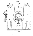
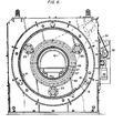
- FIGURES 2 and 5 there is shown a scanning device for examining an object 10 which in the particular instant is a steel sheet piling having extensive length, how long not being of consequence here since the piling or other object 10 is passed through the scanning device.
- the object 10 is examined and by associated measuring apparatus (not shown) certain characteristics are determined or flaws are noted.
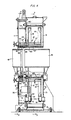
- the scanning device consists ofstands 11,12which supportthree pairs ofrollers 14 having individual rollers 15 and 16 making up each pair. Rollers 15 are supported by stand 11 and rollers 16 are supported adjacent thereto by stand 12. Pairs of rollers 14support and laterally guide a rotating drum 17 and are substantially equispaced around its periphery.
- Rotating drum 17 has flanges 18 and 19 extending therefrom.
- a practical embodiment for such a rotating drum 17 with flanges 18, 19 may have a diameter measuring 218, 5 cm (86 inch.).
- Flange 18 is supported on rollers 15 with a flange 21 on each of rollers 15 riding in notch 22 of flange 18, and flange 19 of rotating drum 17 riding on rollers 16.
- Prevention of sideward movement or wobble of drum 17 is further controlled by a pair of horizontally adjustable bearings 23, one of which shown in FIG. 5 supported on a stand 24, which press outward against the inner oppositely facing surfaces offlanges 18,19 of drum 17.
- Rollers 15 and 16 as shown in FIG. 4 have been rotated sixty degrees from actual position for clarity with stand 24 omitted, and are located as shown in their positions in FIG. 5 where the stand 24 is also shown.
- gamma ray sources 25 equally spaced on a circle concentric with the center of drum 17 and rotatable with drum 17.
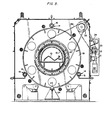
- Rotating drum 17 is rotated by a variable speed drive 30 and sprocket and chain connections shown in FIG. 5 and to an extent in FIG. 6.
- Variable speed drive 30 operates sprocket 31, moving chain 32, rotating sprocket 33, which in turn moves chain 34 thereby rotating sprocket 35.
- Sprocket 35 rotates sprocket 38, being mounted on a shaft common to both. Sprocket 38 thereby moves chain 36.
- Chain rotates sprocket 39 which is connected to drum 17.
- a stationary ring 40 is attached at its periphery to stand 11 this being on the same side of rotating drum 17 to which gamma ray sources 25 are connected. Located between stand 11 and stationary ring 40 are one hundred twenty eight gamma ray detectors 41 horizontally positioned concentric with the center line of drum 17 and outside the circle containing sources 25.
- the circular lead shutter consists of two halves 43 and 44 provided to shield the area from radiation during normal operation as well as during emergency procedures.
- shutter-half 43 rotates with drum 17 while shutter-half 44 remains stationary.
- Shutter-half 44 can be moved horizontally by means of motorized drive 45 located alongside variable speed drive 30 and therefore both are not seen in the same side elevation views.
- Motorized drive 45 and connections to the shutter are shown in Figs. 3 and 4.
- Motorized drive 45 is connected to turn sprocket 46, moving chain 47 around sprocket 48.
- Sprockets 49-53 are all connected by chain 54 to rotate with sprocket 48.
- the rotation of sprockets 48, 50 and 52 causes rotation of screws extending from each sprocket into shutter-half 44 to move shutter-half 44 toward or away from interfitting shutter-half 43.
- Sprockets 49, 51 and 53 are idlers, mounted on guide pins which support shutter-half 44. This movement of edge 58 of shutter-half 44 toward and away from edge 57 of shutter-half 43 is used to adjust the width of the gamma ray beam emitted by radiation sources 25.
- Shutter-half 44 can also be moved horizontally to contact shutter-half 43 wherein edges 57 and 58 are interfitting in order to interrupt the gamma ray beam for shut-down or emergency purposes.
- the drive 45 can be automatically operated or manually controlled from a remote station.
- the fluid cooling jacket encloses the tunnel or side guards 61 by spaced apart concentric plates 64, 65 forming cooling jacket section 62, and spaced apart concentric plates 66, 67 forming cooling jacket section 63, with piped fluid inlets and outlets to each of sections 62, 63. Fluid is exhausted into the interior of the apparatus to provide a positive pressure for the exclusion of dust or other foreign matter.
- the adjacent edges of plates 67 and 65 are spaced apart a distance at least that of the maximum separation of edges 57 and 58 of the shutter-halves 43 and 44 so as not to interfere with the gamma ray beam even at the widest opening of the circular lead shutter.
- Plates 64 and 66 are connected together by a plate having a reduced thickness in the area where the gamma ray beam passes through the shutter-halves 43 and 44.
- the entire device is enclosed and has no external moving parts except for short lengths of sprocket chains. But sources are readily accessible for disarming through covers 70, 72 and 73 or removal through removal covers 70 and 71. Detectors are also easily removed through stationary ring 40.
Landscapes
- Physics & Mathematics (AREA)
- Engineering & Computer Science (AREA)
- General Engineering & Computer Science (AREA)
- High Energy & Nuclear Physics (AREA)
- Health & Medical Sciences (AREA)
- General Health & Medical Sciences (AREA)
- Life Sciences & Earth Sciences (AREA)
- Chemical & Material Sciences (AREA)
- Analytical Chemistry (AREA)
- Biochemistry (AREA)
- General Physics & Mathematics (AREA)
- Immunology (AREA)
- Pathology (AREA)
- Spectroscopy & Molecular Physics (AREA)
- Toxicology (AREA)
- Analysing Materials By The Use Of Radiation (AREA)
- Measurement Of Radiation (AREA)
- Separation By Low-Temperature Treatments (AREA)
- Preparation Of Compounds By Using Micro-Organisms (AREA)
- Saccharide Compounds (AREA)
- Apparatus For Radiation Diagnosis (AREA)
- Investigating Or Analysing Biological Materials (AREA)
Claims (9)
Priority Applications (1)
| Application Number | Priority Date | Filing Date | Title |
|---|---|---|---|
| AT83106983T ATE22728T1 (de) | 1982-07-19 | 1983-07-16 | Strahlungsabtast- und -messvorrichtung. |
Applications Claiming Priority (2)
| Application Number | Priority Date | Filing Date | Title |
|---|---|---|---|
| US06/399,501 US4511801A (en) | 1982-07-19 | 1982-07-19 | Radiation scanning and measuring device |
| US399501 | 1995-03-07 |
Publications (2)
| Publication Number | Publication Date |
|---|---|
| EP0099560A1 EP0099560A1 (de) | 1984-02-01 |
| EP0099560B1 true EP0099560B1 (de) | 1986-10-08 |
Family
ID=23579757
Family Applications (1)
| Application Number | Title | Priority Date | Filing Date |
|---|---|---|---|
| EP83106983A Expired EP0099560B1 (de) | 1982-07-19 | 1983-07-16 | Strahlungsabtast- und -messvorrichtung |
Country Status (11)
| Country | Link |
|---|---|
| US (1) | US4511801A (de) |
| EP (1) | EP0099560B1 (de) |
| JP (1) | JPS5932442A (de) |
| KR (1) | KR870001909B1 (de) |
| AT (1) | ATE22728T1 (de) |
| AU (1) | AU556207B2 (de) |
| BR (1) | BR8303773A (de) |
| CA (1) | CA1214887A (de) |
| DE (1) | DE3366735D1 (de) |
| FI (1) | FI81215C (de) |
| ZA (1) | ZA834585B (de) |
Families Citing this family (4)
| Publication number | Priority date | Publication date | Assignee | Title |
|---|---|---|---|---|
| FR2576102B1 (fr) * | 1985-01-16 | 1987-02-06 | Aerospatiale | Procede et dispositif de tomodensitometrie quantitative |
| US4951222A (en) * | 1988-06-09 | 1990-08-21 | Bethlehem Steel Corporation | Method and system for dimensional and weight measurements of articles of manufacture by computerized tomography |
| US5075554A (en) * | 1990-09-27 | 1991-12-24 | Siemens Gammasonics, Inc. | Scintillation camera gantry supporting a plurality of detector heads between two parallel plates |
| US9480440B2 (en) * | 2011-09-28 | 2016-11-01 | Qr Srl | System and method for cone beam computed tomography |
Family Cites Families (13)
| Publication number | Priority date | Publication date | Assignee | Title |
|---|---|---|---|---|
| US2362911A (en) * | 1942-10-05 | 1944-11-14 | Int Standard Electric Corp | Liquid cooling of high temperature bodies |
| FR1354942A (fr) * | 1963-01-29 | 1964-03-13 | Commissariat Energie Atomique | Obturateur à rideaux pour la radiographie, notamment des combustibles nucléaires irradiés |
| DE1564235C3 (de) * | 1966-07-08 | 1974-11-14 | Kernforschungsanlage Juelich Gmbh, 5170 Juelich | Strahlenverschluß |
| US3562531A (en) * | 1967-04-27 | 1971-02-09 | Ind Nucieonics Corp | Nucleonic measuring apparatus with automatic fire safety radiation source shutter closing and locking means comprising a spring retained by a fusible barrier which melts at high temperatures |
| US3526798A (en) * | 1968-05-20 | 1970-09-01 | Varian Associates | X-ray shield structure for liquid cooled electron beam collectors and tubes using same |
| US3684887A (en) * | 1970-03-26 | 1972-08-15 | Schlumberger Technology Corp | Apparatus for inspecting tubular goods having an automatic shutter |
| US3808437A (en) * | 1972-05-15 | 1974-04-30 | Nippon Steel Corp | Method of thickness measurement for long sections and apparatus therefor |
| US3835323A (en) * | 1972-08-07 | 1974-09-10 | J Kahil | Radiation inspection apparatus with adjustable shutter for inspecting different sizes of tubular goods |
| FR2276667A1 (fr) * | 1974-06-28 | 1976-01-23 | Kernforschungsanlage Juelich | Diaphragme a ouverture reglable de facon continue |
| US4200800A (en) * | 1977-11-03 | 1980-04-29 | American Science & Engineering, Inc. | Reduced dose CT scanning |
| US4284895A (en) * | 1978-02-21 | 1981-08-18 | Ira Lon Morgan | Method and apparatus for tomographic examination of an object by penetrating radiation |
| US4239972A (en) * | 1978-04-24 | 1980-12-16 | U.S. Philips Corporation | Device for computed tomography |
| JPS55129781A (en) * | 1979-03-30 | 1980-10-07 | Kagaku Gijutsucho Hoshasen Igaku Sogo Kenkyusho | Proton cross tomography unit |
-
1982
- 1982-07-19 US US06/399,501 patent/US4511801A/en not_active Expired - Fee Related
-
1983
- 1983-06-23 ZA ZA834585A patent/ZA834585B/xx unknown
- 1983-07-06 KR KR1019830003079A patent/KR870001909B1/ko not_active Expired
- 1983-07-14 BR BR8303773A patent/BR8303773A/pt not_active IP Right Cessation
- 1983-07-16 EP EP83106983A patent/EP0099560B1/de not_active Expired
- 1983-07-16 AT AT83106983T patent/ATE22728T1/de not_active IP Right Cessation
- 1983-07-16 DE DE8383106983T patent/DE3366735D1/de not_active Expired
- 1983-07-18 FI FI832615A patent/FI81215C/fi not_active IP Right Cessation
- 1983-07-18 AU AU16951/83A patent/AU556207B2/en not_active Ceased
- 1983-07-18 CA CA000432649A patent/CA1214887A/en not_active Expired
- 1983-07-19 JP JP58132652A patent/JPS5932442A/ja active Pending
Also Published As
| Publication number | Publication date |
|---|---|
| KR840005558A (ko) | 1984-11-14 |
| CA1214887A (en) | 1986-12-02 |
| DE3366735D1 (en) | 1986-11-13 |
| FI832615A0 (fi) | 1983-07-18 |
| AU1695183A (en) | 1984-01-26 |
| ZA834585B (en) | 1984-03-28 |
| FI832615L (fi) | 1984-01-20 |
| BR8303773A (pt) | 1984-02-21 |
| KR870001909B1 (ko) | 1987-10-21 |
| ATE22728T1 (de) | 1986-10-15 |
| AU556207B2 (en) | 1986-10-23 |
| EP0099560A1 (de) | 1984-02-01 |
| JPS5932442A (ja) | 1984-02-21 |
| FI81215C (fi) | 1990-09-10 |
| US4511801A (en) | 1985-04-16 |
| FI81215B (fi) | 1990-05-31 |
Similar Documents
| Publication | Publication Date | Title |
|---|---|---|
| JP7641183B2 (ja) | 被験者のct検査を実行するctスキャナ及び方法 | |
| US5757878A (en) | Detector arrangement for x-ray tomography system | |
| ES485935A1 (es) | Un aparato para inspeccionar articulos | |
| CA2910117C (en) | Meat processing device incorporating an x-ray analyzer | |
| US4511801A (en) | Radiation scanning and measuring device | |
| US4137455A (en) | Medical radiographic apparatus with means for notating detector ring | |
| ES8407234A1 (es) | Un aparato para alojar componentes irradiados eliminados de un generador nuclear de vapor | |
| CN108449985A (zh) | 用于物体的非破坏性的材料测试的装置 | |
| US4464776A (en) | Multiplexing signal processing channels in a CT scanner with rotating source | |
| CN105158282A (zh) | 一种用于背散射成像系统的扫描装置 | |
| US2704331A (en) | Adjustable mount for X-ray diffraction crystal | |
| JPH11183407A (ja) | X線異物検査装置 | |
| CN211086641U (zh) | 一种x射线透射和背散射一体化检测装置 | |
| US4246484A (en) | Medical radiographic apparatus | |
| GB2265002A (en) | Variable gamma ray collimator for fuel element measurements | |
| US4206362A (en) | Medical radiographic apparatus | |
| KR101351807B1 (ko) | 가변차폐부를 구비하는x선 분석기구 | |
| JPH0862158A (ja) | シールド部材を備えたx線装置 | |
| CA1073120A (en) | Apparatus for scanning an object by means of radioactive or x-ray radiation | |
| EP0107280A2 (de) | Apparat zur Führung eines Kabels durch eine Strahlungskammer mit verminderter Leckage | |
| JPH11183405A (ja) | X線異物検査装置 | |
| CN120103504A (zh) | 安检设备 | |
| US5844955A (en) | Apparatus and method for inspecting an outer jacket of a core containment in the region of a heat shield surrounding the core containment | |
| JP3804687B2 (ja) | X線異物検査装置 | |
| HU192742B (en) | Apparatus for irradiating coiled materials with electron beam |
Legal Events
| Date | Code | Title | Description |
|---|---|---|---|
| PUAI | Public reference made under article 153(3) epc to a published international application that has entered the european phase |
Free format text: ORIGINAL CODE: 0009012 |
|
| AK | Designated contracting states |
Designated state(s): AT BE DE FR GB IT LU NL SE |
|
| 17P | Request for examination filed |
Effective date: 19840725 |
|
| GRAA | (expected) grant |
Free format text: ORIGINAL CODE: 0009210 |
|
| AK | Designated contracting states |
Kind code of ref document: B1 Designated state(s): AT BE DE FR GB IT LU NL SE |
|
| REF | Corresponds to: |
Ref document number: 22728 Country of ref document: AT Date of ref document: 19861015 Kind code of ref document: T |
|
| REF | Corresponds to: |
Ref document number: 3366735 Country of ref document: DE Date of ref document: 19861113 |
|
| ITF | It: translation for a ep patent filed | ||
| EN | Fr: translation not filed | ||
| PG25 | Lapsed in a contracting state [announced via postgrant information from national office to epo] |
Ref country code: LU Free format text: LAPSE BECAUSE OF NON-PAYMENT OF DUE FEES Effective date: 19870731 |
|
| PLBE | No opposition filed within time limit |
Free format text: ORIGINAL CODE: 0009261 |
|
| STAA | Information on the status of an ep patent application or granted ep patent |
Free format text: STATUS: NO OPPOSITION FILED WITHIN TIME LIMIT |
|
| 26N | No opposition filed | ||
| ET | Fr: translation filed | ||
| PGFP | Annual fee paid to national office [announced via postgrant information from national office to epo] |
Ref country code: AT Payment date: 19900611 Year of fee payment: 8 |
|
| PGFP | Annual fee paid to national office [announced via postgrant information from national office to epo] |
Ref country code: GB Payment date: 19900614 Year of fee payment: 8 |
|
| PGFP | Annual fee paid to national office [announced via postgrant information from national office to epo] |
Ref country code: FR Payment date: 19900615 Year of fee payment: 8 |
|
| PGFP | Annual fee paid to national office [announced via postgrant information from national office to epo] |
Ref country code: SE Payment date: 19900619 Year of fee payment: 8 |
|
| PGFP | Annual fee paid to national office [announced via postgrant information from national office to epo] |
Ref country code: DE Payment date: 19900620 Year of fee payment: 8 |
|
| PGFP | Annual fee paid to national office [announced via postgrant information from national office to epo] |
Ref country code: LU Payment date: 19900625 Year of fee payment: 8 |
|
| PGFP | Annual fee paid to national office [announced via postgrant information from national office to epo] |
Ref country code: BE Payment date: 19900712 Year of fee payment: 8 |
|
| ITTA | It: last paid annual fee | ||
| PGFP | Annual fee paid to national office [announced via postgrant information from national office to epo] |
Ref country code: NL Payment date: 19900731 Year of fee payment: 8 |
|
| PG25 | Lapsed in a contracting state [announced via postgrant information from national office to epo] |
Ref country code: GB Effective date: 19910716 Ref country code: AT Effective date: 19910716 |
|
| PG25 | Lapsed in a contracting state [announced via postgrant information from national office to epo] |
Ref country code: SE Effective date: 19910717 |
|
| PG25 | Lapsed in a contracting state [announced via postgrant information from national office to epo] |
Ref country code: BE Effective date: 19910731 |
|
| BERE | Be: lapsed |
Owner name: BETHLEHEM STEEL CORP. Effective date: 19910731 |
|
| PG25 | Lapsed in a contracting state [announced via postgrant information from national office to epo] |
Ref country code: NL Effective date: 19920201 |
|
| GBPC | Gb: european patent ceased through non-payment of renewal fee | ||
| NLV4 | Nl: lapsed or anulled due to non-payment of the annual fee | ||
| PG25 | Lapsed in a contracting state [announced via postgrant information from national office to epo] |
Ref country code: FR Effective date: 19920331 |
|
| PG25 | Lapsed in a contracting state [announced via postgrant information from national office to epo] |
Ref country code: DE Effective date: 19920401 |
|
| REG | Reference to a national code |
Ref country code: FR Ref legal event code: ST |
|
| EUG | Se: european patent has lapsed |
Ref document number: 83106983.6 Effective date: 19920210 |