EP0099587A2 - Racle pour imprimer des objets par sérigraphie - Google Patents
Racle pour imprimer des objets par sérigraphie Download PDFInfo
- Publication number
- EP0099587A2 EP0099587A2 EP83107202A EP83107202A EP0099587A2 EP 0099587 A2 EP0099587 A2 EP 0099587A2 EP 83107202 A EP83107202 A EP 83107202A EP 83107202 A EP83107202 A EP 83107202A EP 0099587 A2 EP0099587 A2 EP 0099587A2
- Authority
- EP
- European Patent Office
- Prior art keywords
- doctor
- squeegee
- head according
- rubber
- clamping
- Prior art date
- Legal status (The legal status is an assumption and is not a legal conclusion. Google has not performed a legal analysis and makes no representation as to the accuracy of the status listed.)
- Granted
Links
- 238000007650 screen-printing Methods 0.000 title claims abstract description 5
- 238000007639 printing Methods 0.000 claims abstract description 21
- 238000000034 method Methods 0.000 claims abstract description 7
- 230000006835 compression Effects 0.000 claims description 3
- 238000007906 compression Methods 0.000 claims description 3
- 238000006073 displacement reaction Methods 0.000 claims description 2
- 239000000463 material Substances 0.000 description 5
- 238000010276 construction Methods 0.000 description 2
- 230000000694 effects Effects 0.000 description 1
- 238000002474 experimental method Methods 0.000 description 1
- 230000007257 malfunction Effects 0.000 description 1
- 238000004806 packaging method and process Methods 0.000 description 1
Images

Classifications
-
- B—PERFORMING OPERATIONS; TRANSPORTING
- B41—PRINTING; LINING MACHINES; TYPEWRITERS; STAMPS
- B41F—PRINTING MACHINES OR PRESSES
- B41F15/00—Screen printers
- B41F15/14—Details
- B41F15/44—Squeegees or doctors
- B41F15/46—Squeegees or doctors with two or more operative parts
Definitions
- the present invention relates to a squeegee head for printing bodies using the screen printing method, with a squeegee rubber and a holder which detects it.
- doctor heads whose holder consists of two strips arranged next to one another and running over the entire length of the doctor rubber, between which the doctor rubber is clamped.
- the elasticity of the rubber material is used in such known squeegee heads. This is done in such a way that the clamping point of the squeegee rubber between the strips is provided at a certain distance from the working edge of the squeegee rubber. The rubber material between the working edge and the clamping point then develops a uniform pressure over the entire length of the working edge due to its elasticity when the working edge is pressed against the screen template.
- doctor blade heads A disadvantage of such known doctor blade heads is that the elasticity of the doctor blade rubber diminishes after a relatively short period of use, so that the doctor blade rubber dodges and is no longer able to produce the contact pressure required for a satisfactory printing result. This effect, commonly referred to as “flipping", requires frequent replacement of the squeegee rubber, so that the service life of such constructions is relatively short.
- the object of the present invention is to provide a completely new doctor head which, with a longer service life and lower consumption of doctor rubber, enables an error-free printing result even with an uneven body surface.
- the holder consists of a number of juxtaposed holder parts which are guided in the doctor head independently of each other back and forth in the pressing direction and are held under a pressing force.
- a doctor head is created for the first time, in which instead of two strips running over the entire length of the doctor rubber as a holder for the doctor rubber, a number of side by side is indicated arranged and each independently movable and held under a pressing force holding parts are provided. Due to this configuration, the A is ndtikkraft at the working edge no longer by the doctor blade rubber material itself but by means independent thereof generated, so that the size of the Andtikkraft is completely independent of the elasticity of the squeegee rubber. The result is a significantly longer service life with the resulting advantages in terms of the consumption of rubber material.
- doctor blade rubber can be clamped in for a very short time due to the separate means for generating the pressure force, considerably narrower doctor blade rubber strips can also be used without disadvantages for the quality of the printing result. This results in a reduction in doctor blade rubber consumption of over 50%.
- the holder of the squeegee rubber according to the invention in mutually independent holder parts also has the advantage that unevenness on the body surface no longer plays a significant role for the printing result.
- the squeegee rubber can better follow any unevenness in the printing process due to the fixing in mutually independent holding parts than in the case of clamping via continuous strips, so that a reject reduction of up to 50% is possible, especially since those surfaces of the body which are designed according to the invention can also be printed on previously had to be sorted out before printing due to unevenness.
- doctor head designed according to the invention to be able to adapt to unevenness better than known doctor heads also leads to improved printing results for bodies with different wall thicknesses over the printing length.
- the working edge of the squeegee rubber can better follow thin wall areas which have a greater tendency to dodge compared to thick wall areas, so that better printing results can be achieved even in such cases.
- a particularly important advantage of a doctor head according to the invention is, however, that it is also possible without difficulty to print on those surfaces which, viewed over the length of the printed image, have different radii.
- the squeegee rubber can follow a change in radius during the printing process due to the holder in mutually independent holder parts, so that even surfaces can be printed whose radius changes greatly over the length of the printed image.
- doctor blade rubber is clamped in a particularly flexible manner if the holding parts are not arranged directly next to one another but at a short distance from one another. This distance depends on the Shore hardness and the thickness of the doctor blade rubber material.
- the displacement of the holder parts in the pressing direction can be limited by adjustable stops.
- the squeegee can be given a shape adapted to the surface to be printed if necessary.
- the pressure force for the individual mounting parts can be generated in a variety of ways.
- small power cylinders can be provided to generate the pressure force.
- compression springs are provided to generate the pressure force.
- each holding part consists of a clamping head for the Squeegee rubber, which is connected to a guide pin on its side opposite the squeegee rubber.
- the stops can be designed in a wide variety of ways. However, it is expedient if the stops are each formed by a nut with a lock nut, which is arranged on a thread of the guide pin.
- the guide pins can be connected to the clamping head in a variety of ways. A particularly advantageous embodiment results, however, when the guide pin rests in a bore in the clamping piece and is held by a cross pin.
- the squeegee can be attached to the mounting parts in a variety of ways. It is expedient if the holding parts have a clamping slot for the squeegee rubber.
- This clamping slot can be formed in a conventional manner by two clamping jaws which can be screwed together. A particularly simple configuration results, however, if the clamping slot is formed only by a groove, the width of which is slightly smaller than the width of the squeegee rubber. Tests have shown that such a design is completely sufficient to securely fix a squeegee rubber in the holder parts or their clamping head.
- the clamping slot is inclined at an angle to the pressing direction.
- the squeegee is tilted so that one of its edges acts as a working edge.
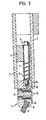
- the doctor head consists of a flat box-like housing 1, the front surface of which is formed by a removable cover plate 2.
- a strip 3 which has a number of bores for guide pins 4 arranged next to one another, which have a nut arrangement consisting of a nut 5 and a lock nut 6 at one end and a clamping head 7 at each other end.
- the clamping heads 7 have an approximately rectangular cross section and are guided so that they can be pushed back and forth in slots in the housing 1 of the doctor head.
- the clamping heads 7 have clamping slots 8 in the area of their chamfered end face protruding from the housing for receiving a doctor blade rubber 9, which in the present case has an approximately rectangular cross section.
- the clamp slots 8 are also inclined at an angle to the pressing direction, which in the present case runs in a plane through the axes of the guide pins 4.
- the pins 4 rest in a bore in the clamping heads 7.
- the guide pins 4 are fastened with the clamping heads 7 by means of a cross pin 10.
- the clamping heads 7 each consist of two clamping jaws 13 and 14, which are connected to one another by screws 12 and between which the squeegee rubber 9 is clamped.
- the guide pin 4 is provided at its end opposite the nut 5 with a threaded pin 15 which is screwed into a threaded bore 16 of the clamping head 7.
Landscapes
- Engineering & Computer Science (AREA)
- Mechanical Engineering (AREA)
- Screen Printers (AREA)
Priority Applications (1)
| Application Number | Priority Date | Filing Date | Title |
|---|---|---|---|
| AT83107202T ATE28825T1 (de) | 1982-07-23 | 1983-07-22 | Rakelkopf zum bedrucken von koerpern im siebdruckverfahren. |
Applications Claiming Priority (2)
| Application Number | Priority Date | Filing Date | Title |
|---|---|---|---|
| DE19823227626 DE3227626A1 (de) | 1982-07-23 | 1982-07-23 | Rakelkopf zum bedrucken von koerpern im siebdruckverfahren |
| DE3227626 | 1982-07-23 |
Publications (3)
| Publication Number | Publication Date |
|---|---|
| EP0099587A2 true EP0099587A2 (fr) | 1984-02-01 |
| EP0099587A3 EP0099587A3 (en) | 1985-05-15 |
| EP0099587B1 EP0099587B1 (fr) | 1987-08-12 |
Family
ID=6169195
Family Applications (1)
| Application Number | Title | Priority Date | Filing Date |
|---|---|---|---|
| EP83107202A Expired EP0099587B1 (fr) | 1982-07-23 | 1983-07-22 | Racle pour imprimer des objets par sérigraphie |
Country Status (3)
| Country | Link |
|---|---|
| EP (1) | EP0099587B1 (fr) |
| AT (1) | ATE28825T1 (fr) |
| DE (2) | DE3227626A1 (fr) |
Cited By (6)
| Publication number | Priority date | Publication date | Assignee | Title |
|---|---|---|---|---|
| US5078061A (en) * | 1988-04-16 | 1992-01-07 | Elmar Messerschmitt | Doctor for screen printing |
| EP0937577A1 (fr) * | 1998-02-18 | 1999-08-25 | FUJI MACHINE Mfg. Co., Ltd. | Machine d'impression pour déposer de la soudure |
| FR2935925A1 (fr) * | 2008-09-16 | 2010-03-19 | Dubuit Mach | Support de racle et outil de desserrage de ce support de racle. |
| WO2016019245A1 (fr) * | 2014-08-01 | 2016-02-04 | Corning Incorporated | Appareil et procédés de sérigraphie |
| US10350879B2 (en) | 2014-08-01 | 2019-07-16 | Corning Incorporated | Screen printing apparatus and methods |
| DE202020102567U1 (de) | 2020-05-07 | 2020-05-19 | GST Dekortechnik GmbH | Verpackung für eine Rakel für eine Vorrichtung zum Bedrucken von Flächen und Körpern im Siebdruckverfahren |
Families Citing this family (7)
| Publication number | Priority date | Publication date | Assignee | Title |
|---|---|---|---|---|
| DE3812826A1 (de) * | 1987-07-03 | 1989-01-12 | Elmar Dr Messerschmitt | Rakel fuer den siebdruck |
| US5458060A (en) * | 1993-05-03 | 1995-10-17 | Sony Electronics Inc. | Screen printing squeegee system |
| DE20303187U1 (de) | 2003-02-27 | 2003-04-30 | Gst Dekoracni Zarizeni A Strojni Tecnika S.R.O., Hranice | Rakelkopf zum Bedrucken von Körpern im Siebdruckverfahren |
| DE10344023B4 (de) * | 2003-09-16 | 2006-06-14 | Thieme Gmbh & Co. Kg | Siebdruckrakel und Vorrichtung zum Siebdrucken |
| DE202011107661U1 (de) * | 2011-11-07 | 2013-02-08 | Thieme Gmbh & Co. Kg | Siebdruckrakel und Vorrichtung zum Siebdrucken |
| CN102909942B (zh) * | 2012-10-05 | 2014-10-22 | 梧州市光华纺织制品有限责任公司 | 刮刀调节装置 |
| DE102023121619A1 (de) | 2023-08-11 | 2025-02-13 | Klemens Welsch | Rakelgummi, Rakelkopf und Rakelsystem |
Family Cites Families (4)
| Publication number | Priority date | Publication date | Assignee | Title |
|---|---|---|---|---|
| DE1819026U (de) * | 1960-01-30 | 1960-10-06 | Andreas Peschl | Verstellbare und federnde rakel fuer siebdruckmaschinen im rund- und flachdruck. |
| DE1536985A1 (de) * | 1966-10-14 | 1970-02-26 | Knappstein Kg A | Rakel fuer Siebdruckgeraete |
| US3483819A (en) * | 1967-05-18 | 1969-12-16 | Precision Systems Co Inc | Squeegee assembly for screen process printers of micro-circuits and components thereof |
| DE2302728A1 (de) * | 1973-01-19 | 1974-07-25 | Kesper Hans Ulrich | Siebdruckrakeleinrichtung |
-
1982
- 1982-07-23 DE DE19823227626 patent/DE3227626A1/de not_active Ceased
-
1983
- 1983-07-22 EP EP83107202A patent/EP0099587B1/fr not_active Expired
- 1983-07-22 DE DE8383107202T patent/DE3372944D1/de not_active Expired
- 1983-07-22 AT AT83107202T patent/ATE28825T1/de not_active IP Right Cessation
Cited By (10)
| Publication number | Priority date | Publication date | Assignee | Title |
|---|---|---|---|---|
| US5078061A (en) * | 1988-04-16 | 1992-01-07 | Elmar Messerschmitt | Doctor for screen printing |
| EP0937577A1 (fr) * | 1998-02-18 | 1999-08-25 | FUJI MACHINE Mfg. Co., Ltd. | Machine d'impression pour déposer de la soudure |
| US6112656A (en) * | 1998-02-18 | 2000-09-05 | Fuji Machine Mfg. Co., Ltd. | Creamed-solder printing machine |
| FR2935925A1 (fr) * | 2008-09-16 | 2010-03-19 | Dubuit Mach | Support de racle et outil de desserrage de ce support de racle. |
| US8393268B2 (en) | 2008-09-16 | 2013-03-12 | Machines Dubuit | Doctor blade support and tool for loosening that doctor blade support |
| WO2016019245A1 (fr) * | 2014-08-01 | 2016-02-04 | Corning Incorporated | Appareil et procédés de sérigraphie |
| CN107073927A (zh) * | 2014-08-01 | 2017-08-18 | 康宁股份有限公司 | 丝网印刷装置和方法 |
| EP3456534A1 (fr) * | 2014-08-01 | 2019-03-20 | Corning Incorporated | Appareil de sérigraphie |
| US10350879B2 (en) | 2014-08-01 | 2019-07-16 | Corning Incorporated | Screen printing apparatus and methods |
| DE202020102567U1 (de) | 2020-05-07 | 2020-05-19 | GST Dekortechnik GmbH | Verpackung für eine Rakel für eine Vorrichtung zum Bedrucken von Flächen und Körpern im Siebdruckverfahren |
Also Published As
| Publication number | Publication date |
|---|---|
| DE3227626A1 (de) | 1984-01-26 |
| EP0099587A3 (en) | 1985-05-15 |
| EP0099587B1 (fr) | 1987-08-12 |
| ATE28825T1 (de) | 1987-08-15 |
| DE3372944D1 (en) | 1987-09-17 |
Similar Documents
| Publication | Publication Date | Title |
|---|---|---|
| DE2730800C3 (de) | Messeranordnung fur eine Schragschnlttmesserwelle einer Holzzerspanungsmaschüie | |
| EP0099587B1 (fr) | Racle pour imprimer des objets par sérigraphie | |
| EP0374092B1 (fr) | Encrier pour machine d'impression | |
| DE4012825C2 (fr) | ||
| DE2346355C3 (de) | Druckvorrichtung | |
| AT404694B (de) | Siebdruckrakel-system | |
| AT392601B (de) | Vorrichtung zum regeln der auftragsstaerke beim beschichten laufender materialbahnen | |
| EP0236773A2 (fr) | Dispositif servant à régler la distance entre la tête d'impression et l'appui d'une imprimante, notamment d'une imprimante à matrice | |
| DE2339630B2 (de) | Vorrichtung zum Konstanthalten des Abstandes zwischen den Druckelementen eines Mosaikdruckkopfes und einem Aufzeichnungsträger | |
| DE3528642A1 (de) | Verfahren und anordnung zum einpraegen von kanaelen mit geringem querschnitt in die oberflaeche eines werkstuecks | |
| DE1785298C3 (de) | Drucktisch | |
| EP0040287A1 (fr) | Dispositif de dosage de l'encre dans un encrier pour machines à imprimer offset ou presses typographiques | |
| DE2103462A1 (de) | Typenträger fur Schreibmaschinen oder dergleichen | |
| DE3021823C2 (de) | Lagerteil mit einer Aufnahmebohrung für eine Stange oder Welle | |
| DE69903490T2 (de) | Farbwerk | |
| DE2311899B2 (de) | Vorrichtung zum schleifen von bandsaegezaehnen | |
| DE2411075A1 (de) | Folienschneideinrichtung | |
| DE2340980C2 (de) | Vorrichtung zum Befestigen von Druckplatten | |
| DE2100591B2 (de) | Aufzeichnung^- und/oder Wiedergabegerät | |
| EP0008349B1 (fr) | Guidage de précision pour les électrodes d'une tête d'impression multi-électrodes dans des imprimantes à papier métallique | |
| DE3147170C2 (de) | Vorrichtung zum Ausgleich unterschiedlicher Dicken eines Aufzeichnungsträgers entlang einer Druckzeile | |
| DE69515619T2 (de) | Thermodruckkopfhalterung | |
| DE953612C (de) | Flachdruckvervielfaeltiger fuer hektographische Spiegelschrift-Originale | |
| DE2316653C3 (de) | Vorrichtung zum Quereinspannen einer Sortierfläche in eine Schüttelsortiermaschine | |
| DE681083C (de) | Aus einzelnen Schneidplaettchen zusammengesetzte Feile |
Legal Events
| Date | Code | Title | Description |
|---|---|---|---|
| PUAI | Public reference made under article 153(3) epc to a published international application that has entered the european phase |
Free format text: ORIGINAL CODE: 0009012 |
|
| AK | Designated contracting states |
Designated state(s): AT BE CH DE FR GB IT LI NL SE |
|
| RAP1 | Party data changed (applicant data changed or rights of an application transferred) |
Owner name: REBHAN, HORST |
|
| PUAL | Search report despatched |
Free format text: ORIGINAL CODE: 0009013 |
|
| AK | Designated contracting states |
Designated state(s): AT BE CH DE FR GB IT LI NL SE |
|
| 17P | Request for examination filed |
Effective date: 19851115 |
|
| 17Q | First examination report despatched |
Effective date: 19861030 |
|
| ITF | It: translation for a ep patent filed | ||
| GRAA | (expected) grant |
Free format text: ORIGINAL CODE: 0009210 |
|
| AK | Designated contracting states |
Kind code of ref document: B1 Designated state(s): AT BE CH DE FR GB IT LI NL SE |
|
| REF | Corresponds to: |
Ref document number: 28825 Country of ref document: AT Date of ref document: 19870815 Kind code of ref document: T |
|
| ET | Fr: translation filed | ||
| REF | Corresponds to: |
Ref document number: 3372944 Country of ref document: DE Date of ref document: 19870917 |
|
| PLBE | No opposition filed within time limit |
Free format text: ORIGINAL CODE: 0009261 |
|
| STAA | Information on the status of an ep patent application or granted ep patent |
Free format text: STATUS: NO OPPOSITION FILED WITHIN TIME LIMIT |
|
| 26N | No opposition filed | ||
| PGFP | Annual fee paid to national office [announced via postgrant information from national office to epo] |
Ref country code: AT Payment date: 19910725 Year of fee payment: 9 |
|
| PGFP | Annual fee paid to national office [announced via postgrant information from national office to epo] |
Ref country code: SE Payment date: 19910726 Year of fee payment: 9 |
|
| PGFP | Annual fee paid to national office [announced via postgrant information from national office to epo] |
Ref country code: GB Payment date: 19910730 Year of fee payment: 9 |
|
| ITTA | It: last paid annual fee | ||
| PGFP | Annual fee paid to national office [announced via postgrant information from national office to epo] |
Ref country code: NL Payment date: 19910731 Year of fee payment: 9 Ref country code: FR Payment date: 19910731 Year of fee payment: 9 Ref country code: BE Payment date: 19910731 Year of fee payment: 9 |
|
| PGFP | Annual fee paid to national office [announced via postgrant information from national office to epo] |
Ref country code: DE Payment date: 19910814 Year of fee payment: 9 |
|
| PGFP | Annual fee paid to national office [announced via postgrant information from national office to epo] |
Ref country code: CH Payment date: 19911029 Year of fee payment: 9 |
|
| PG25 | Lapsed in a contracting state [announced via postgrant information from national office to epo] |
Ref country code: GB Effective date: 19920722 Ref country code: AT Effective date: 19920722 |
|
| PG25 | Lapsed in a contracting state [announced via postgrant information from national office to epo] |
Ref country code: SE Effective date: 19920723 |
|
| PG25 | Lapsed in a contracting state [announced via postgrant information from national office to epo] |
Ref country code: LI Effective date: 19920731 Ref country code: CH Effective date: 19920731 Ref country code: BE Effective date: 19920731 |
|
| BERE | Be: lapsed |
Owner name: REBHAN HORST Effective date: 19920731 |
|
| PG25 | Lapsed in a contracting state [announced via postgrant information from national office to epo] |
Ref country code: NL Effective date: 19930201 |
|
| NLV4 | Nl: lapsed or anulled due to non-payment of the annual fee | ||
| GBPC | Gb: european patent ceased through non-payment of renewal fee |
Effective date: 19920722 |
|
| PG25 | Lapsed in a contracting state [announced via postgrant information from national office to epo] |
Ref country code: FR Effective date: 19930331 |
|
| REG | Reference to a national code |
Ref country code: CH Ref legal event code: PL |
|
| PG25 | Lapsed in a contracting state [announced via postgrant information from national office to epo] |
Ref country code: DE Effective date: 19930401 |
|
| REG | Reference to a national code |
Ref country code: FR Ref legal event code: ST |
|
| EUG | Se: european patent has lapsed |
Ref document number: 83107202.0 Effective date: 19930204 |