EP0099638A2 - Verfahren und System zur Datenübertragung für eine Bohrlochsonde - Google Patents
Verfahren und System zur Datenübertragung für eine Bohrlochsonde Download PDFInfo
- Publication number
- EP0099638A2 EP0099638A2 EP83303309A EP83303309A EP0099638A2 EP 0099638 A2 EP0099638 A2 EP 0099638A2 EP 83303309 A EP83303309 A EP 83303309A EP 83303309 A EP83303309 A EP 83303309A EP 0099638 A2 EP0099638 A2 EP 0099638A2
- Authority
- EP
- European Patent Office
- Prior art keywords
- digital
- digital data
- borehole
- receiver
- signals
- Prior art date
- Legal status (The legal status is an assumption and is not a legal conclusion. Google has not performed a legal analysis and makes no representation as to the accuracy of the status listed.)
- Withdrawn
Links
- 230000005540 biological transmission Effects 0.000 title claims abstract description 17
- 238000000034 method Methods 0.000 title claims description 12
- 230000015654 memory Effects 0.000 claims abstract description 20
- 230000015572 biosynthetic process Effects 0.000 claims abstract description 14
- 238000005070 sampling Methods 0.000 claims description 7
- 238000006243 chemical reaction Methods 0.000 claims description 4
- 238000005755 formation reaction Methods 0.000 description 11
- 238000010586 diagram Methods 0.000 description 5
- 239000004020 conductor Substances 0.000 description 4
- 230000003321 amplification Effects 0.000 description 2
- 238000005259 measurement Methods 0.000 description 2
- 238000003199 nucleic acid amplification method Methods 0.000 description 2
- 239000007787 solid Substances 0.000 description 2
- 230000001351 cycling effect Effects 0.000 description 1
- 230000007423 decrease Effects 0.000 description 1
- 230000001419 dependent effect Effects 0.000 description 1
- 238000001514 detection method Methods 0.000 description 1
- 230000000694 effects Effects 0.000 description 1
- 230000006870 function Effects 0.000 description 1
- 229910052500 inorganic mineral Inorganic materials 0.000 description 1
- 239000011707 mineral Substances 0.000 description 1
- 239000003208 petroleum Substances 0.000 description 1
- 230000004044 response Effects 0.000 description 1
Images

Classifications
-
- E—FIXED CONSTRUCTIONS
- E21—EARTH OR ROCK DRILLING; MINING
- E21B—EARTH OR ROCK DRILLING; OBTAINING OIL, GAS, WATER, SOLUBLE OR MELTABLE MATERIALS OR A SLURRY OF MINERALS FROM WELLS
- E21B47/00—Survey of boreholes or wells
- E21B47/12—Means for transmitting measuring-signals or control signals from the well to the surface, or from the surface to the well, e.g. for logging while drilling
- E21B47/14—Means for transmitting measuring-signals or control signals from the well to the surface, or from the surface to the well, e.g. for logging while drilling using acoustic waves
-
- G—PHYSICS
- G08—SIGNALLING
- G08C—TRANSMISSION SYSTEMS FOR MEASURED VALUES, CONTROL OR SIMILAR SIGNALS
- G08C19/00—Electric signal transmission systems
- G08C19/16—Electric signal transmission systems in which transmission is by pulses
- G08C19/28—Electric signal transmission systems in which transmission is by pulses using pulse code
Definitions
- This invention relates to a borehole logging tool employing data transmission of borehole logging signals to recording equipment on the surface of the earth.
- a logging tool including a transmitter of acoustic pulses and a receiver, or receivers, for detecting these acoustic pulses after they have traversed the subsurface formations adjacent the tool.
- a logging tool including a transmitter of acoustic pulses and a receiver, or receivers, for detecting these acoustic pulses after they have traversed the subsurface formations adjacent the tool.
- a downhole tool comprises a plurality of transducers including a transmitter and multiple receivers.
- the receivers are spaced at different distances from the transmitter such that an acoustic pulse from the transmitter arrives at the receivers by way of different travel paths through the formation surrounding the borehole.
- a transmitter trigger pulse is transmitted uphole by way of a conductor in the logging cable.
- the analog signals produced by the receivers in response to the arrival of the acoustic pulse at the receivers are also transmitted uphole by way of conductors within the logging cable.
- the logging system is provided with downhole gating circuits which permit the first acoustic pulse to be detected and an analog signal sent uphole by a first receiver, the second acoustic pulse to be detected and an analog signal sent uphole by a second receiver, the third acoustic pulse to be detected and an analog signal sent uphole by a third receiver, and the fourth acoustic pulse to be detected and an analog signal sent uphole by a fourth receiver.
- This multiplexing cycle is then repeated with successive acoustic pulses being detected and transmitted uphole. The time interval-between the generation of each acoustic pulse and the detection of that pulse at a particular receiver is recorded.
- time intervals are combined to provide an indication of acoustic velocity of formations adjacent to the logging tool.
- the influence of variations on the acoustic velocity measurement caused by the borehole medium as the acoustic pulses travel to and from the borehole tool is eliminated so that the measurements are dependent solely upon the character of the subsurface formations surrounding the borehole.
- Receiver signals from borehole logging systems such as described in the aforementioned U.S. patent to Zemanek, Jr., have typically been multiplexed, amplified, filtered, and transmitted over several miles of,logging cable in analog form.
- state-of-the- art logging cables have relatively poor transmission qualities. Consequently, analog data transmission has reached the upper limit of data quality and dynamic range. Further, analog signals must be transmitted in real time. Simultaneous transmission of many channels of analog information requires multiconductor logging cables that are well shielded against crossfeed effects.
- the present invention is directed to overcoming the analog transmission difficulties by transmitting the receiver signals over the several miles of variable quality logging cable in digital form so that such signals can be recovered with full fidelity at the surface of the earth. Also, signals from several receivers can be digitally stored in solid state memories and transmitted over a single conductor at optimum intervals to minimize logging runs through the borehole.
- a method for digitally transmitting said signals along a transmission line to recording equipment on the surface of the earth comprising:
- the invention resides in a borehole logging system comprising:
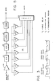
- the data acquisition unit of a borehole logging system includes a preamp 20 and a sample and hold (S/H) circuit 21 which receive an analog voltage signal from a receiver in the borehole logging tool. It is desirable to sample the analog receiver signal at a very high rate, preferably at least 100 kilosamples/second. In one embodiment, the cycling rate was selected as 200 kilosamples/second, or every 5 microseconds.
- a binary gain amplifier (BGA) 22 acts to select and apply a desired gain for each sampled receiver signal.
- An analog-to-digital converter (ADC) 23 converts the amplified analog signals to a digital data word which is stored in a solid state memory 24.
- a select number of the stored digital data words may be stacked at 27 to improve the signal-to-noise ratio.
- Transmission of the stored digital data words is by way of a parallel-to-serial converter 28 and a Manchester encoder 25 which operate to format and convert the digital data words into a digital serial word for telemetry to the surface of the earth over a single conductor 26 of the borehole logging cable.
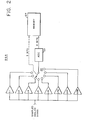
- the binary gain amplifier 22 is programmable up to a gain of 128 through the 8 stages of gain as shown in Figure 2.
- the purpose of such a gain range is to amplify low level receiver signals to a greater extent than the higher level receiver signals so that the analog-to-digital (A/D) converter 23 will always be operating on the highest level signal possible.
- A/D analog-to-digital
- a very low level receiver signal can receive up to 42 db of gain while a high level signal can be passed on through the amplifier 22 with no gain.
- Such an amplitude equalization technique permits the A/D converter 23 to provide optimum analog-to-digital conversion of all receiver analog signals.
- A/D converter 23 provides an 8-bit digital data word for each sampling of the analog signal by the sample and hold circuit 21. To identify the gain applied to such analog signal, the amplifier 22 provides an additional 3-bit digital data word to the memory unit 24. The memory 24 combines these 3-bit and 8-bit digital data words to store an 11-bit digital data word characteristic of the sampled and amplified analog signal.
- the A/D converter 23 provides a dynamic range of 48 db. The total dynamic gain range provided by the combination of the amplifier 22 and A/D converter 23 is 90 db.
- the memory 24 has a storage capability of up to 2048 samples of digital data words of 11 bits each.
- the data acquisition time to complete the memory is 2048 samples times 5 microseconds per sample, or 10.24 milliseconds.
- the Manchester encoder 25 converts the 2048 digital data words into serial format for telemetry to the surface of the earth at a data rate above 100 kilobits per second and preferably at a data rate of 150 kilobits per second or over a time period of 200 milliseconds. This can best be seen by reference to the timing diagram of Figure 3.
- multiplexer 29 permits the selection of the stacker 27 output or the memory 24 output.
- Stacking permits the signal-to-noise ratio of the telemetered digital data to be enhanced by stacking a select number of digital data words from each sampling, for example, 2 to 8 of the 11 bit digital data words stored in memory 24 may be applied to the stacker 27 prior to encoding for telemetry by the parallel-to-serial converter 28 and the Manchester encoder 25.
- Uphole circuitry for receiving and recording the digital serial data words as telemetered over the several miles of logging cable 26.
- Uphole reception is by way of a Manchester decoder 30 which converts the serial stream of digital data back into individual 11 bit digital data words for either storage on a digital storage device 31, such as a digital tape transport, or for conversion back into analog format by the digital- to-analog converter 32 for viewing on a suitable display device 33.
- the analog receiver signal after passing through the preamplifier 20, is applied to the sample and hold 21.
- the analog signal is sampled for about 500 nanoseconds, for example, and then the sampled voltage is held constant for about 4.5 microseconds, for example. It is during this holding period that the analog-to-digital conversion takes place within the A/D converter 23.
- the sampled voltage is converted to an 8 bit digital data word by A/D converter 23 and applied by way of the latch 41 to the memory 42 which is a programmable read only memory (PROM).
- PROM programmable read only memory
- the memory 42 is programmed in conventional look-up table format so as to select a desired dynamic gain based upon the voltage level of the sampled analog receiver signal.
- the desired gain increases in 6 db steps with amplifications x2, x4, x8, xl6, x32, x64 and x128. Likewise, the same gain selection process is carried out for negative voltage levels.
- the output of the memory 42 is a 3 bit binary gain word representing the particular gain selection.
- This binary gain word is applied to the analog switch 43 which selects the particular amplifier in the bank of amplifiers 44 which gives the selected amount of 2 N amplification to the sampled analog receiver signal stored in the sample and hold 21.
- the analog modified voltage output signal (AMVO) from the selected amplifier is then passed on by switch 43 to the A/D converter 23 for digitization while the 3 bit binary gain word (BGW) from the memory 42 is passed on to the memory 24 for inclusion in the 11 bit digital data word generated therein.
- AMVO analog modified voltage output signal
- BGW binary gain word
- circuit elements are merely representative of one embodiment of the present invention. Various other types and values of circuit components may be utilized. In accordance with the preferred embodiment, the following table sets forth specific types and values of the circuit elements.
Landscapes
- Physics & Mathematics (AREA)
- Engineering & Computer Science (AREA)
- Life Sciences & Earth Sciences (AREA)
- Mining & Mineral Resources (AREA)
- Geology (AREA)
- Geophysics (AREA)
- Environmental & Geological Engineering (AREA)
- Fluid Mechanics (AREA)
- Remote Sensing (AREA)
- Acoustics & Sound (AREA)
- General Life Sciences & Earth Sciences (AREA)
- Geochemistry & Mineralogy (AREA)
- General Physics & Mathematics (AREA)
- Geophysics And Detection Of Objects (AREA)
- Perforating, Stamping-Out Or Severing By Means Other Than Cutting (AREA)
- Sampling And Sample Adjustment (AREA)
- Earth Drilling (AREA)
- Arrangements For Transmission Of Measured Signals (AREA)
Applications Claiming Priority (4)
| Application Number | Priority Date | Filing Date | Title |
|---|---|---|---|
| US40033482A | 1982-07-21 | 1982-07-21 | |
| US400334 | 1982-07-21 | ||
| US40080482A | 1982-07-22 | 1982-07-22 | |
| US400804 | 1982-07-22 |
Publications (2)
| Publication Number | Publication Date |
|---|---|
| EP0099638A2 true EP0099638A2 (de) | 1984-02-01 |
| EP0099638A3 EP0099638A3 (de) | 1985-09-11 |
Family
ID=27017003
Family Applications (1)
| Application Number | Title | Priority Date | Filing Date |
|---|---|---|---|
| EP83303309A Withdrawn EP0099638A3 (de) | 1982-07-21 | 1983-06-08 | Verfahren und System zur Datenübertragung für eine Bohrlochsonde |
Country Status (2)
| Country | Link |
|---|---|
| EP (1) | EP0099638A3 (de) |
| NO (1) | NO832489L (de) |
Cited By (4)
| Publication number | Priority date | Publication date | Assignee | Title |
|---|---|---|---|---|
| EP0553908A3 (en) * | 1992-01-21 | 1993-10-20 | Anadrill Int Sa | Method of and apparatus for making near-bit measurements while drilling |
| CN102373917A (zh) * | 2010-08-12 | 2012-03-14 | 刘永军 | 井口监测套管防碰系统 |
| CN101100940B (zh) * | 2006-07-06 | 2012-04-25 | 北京紫贝龙科技有限责任公司 | 一种阵列化声信号检测系统及其工程应用 |
| JP2013050867A (ja) * | 2011-08-31 | 2013-03-14 | Ono Sokki Co Ltd | 送信回路およびトルク測定器 |
Family Cites Families (4)
| Publication number | Priority date | Publication date | Assignee | Title |
|---|---|---|---|---|
| US4012712A (en) * | 1975-03-31 | 1977-03-15 | Schlumberger Technology Corporation | System for telemetering well logging data |
| US4210967A (en) * | 1975-05-27 | 1980-07-01 | Schlumberger Technology Corp. | Method and apparatus for determining acoustic wave parameters in well logging |
| US4214231A (en) * | 1979-03-26 | 1980-07-22 | The United States Of America As Represented By The Secretary Of The Army | In-bore telemetry information measuring system |
| GB2050770A (en) * | 1979-06-01 | 1981-01-07 | Shell Int Research | Transmitting signals from well to earth surface |
-
1983
- 1983-06-08 EP EP83303309A patent/EP0099638A3/de not_active Withdrawn
- 1983-07-07 NO NO832489A patent/NO832489L/no unknown
Cited By (4)
| Publication number | Priority date | Publication date | Assignee | Title |
|---|---|---|---|---|
| EP0553908A3 (en) * | 1992-01-21 | 1993-10-20 | Anadrill Int Sa | Method of and apparatus for making near-bit measurements while drilling |
| CN101100940B (zh) * | 2006-07-06 | 2012-04-25 | 北京紫贝龙科技有限责任公司 | 一种阵列化声信号检测系统及其工程应用 |
| CN102373917A (zh) * | 2010-08-12 | 2012-03-14 | 刘永军 | 井口监测套管防碰系统 |
| JP2013050867A (ja) * | 2011-08-31 | 2013-03-14 | Ono Sokki Co Ltd | 送信回路およびトルク測定器 |
Also Published As
| Publication number | Publication date |
|---|---|
| NO832489L (no) | 1984-01-23 |
| EP0099638A3 (de) | 1985-09-11 |
Similar Documents
| Publication | Publication Date | Title |
|---|---|---|
| US4581725A (en) | Method and system for gain selection | |
| US4901289A (en) | System for acquiring and recording signals delivered by a set of sensors disposed in well probes | |
| US4319347A (en) | Seismic method and system of improved resolution and discrimination | |
| US4414651A (en) | Integrated well logging system and method | |
| IL42918A (en) | Method of land seismic exploration and apparatus for recording seismic data | |
| EP0285519A1 (de) | Gerät zur bohrlochseismischen Datensammlung und ihre Übertragung zu einer zentralen Steuerungs- und Registrieranordnung | |
| US4797668A (en) | Acoustic well logging system having multiplexed filter digitizing | |
| US3388375A (en) | Magnetic tape recording methods and apparatus for well logging | |
| US4684947A (en) | Simultaneous digitizing apparatus for an acoustic tool | |
| Bradner et al. | Comparative seismic noise on the ocean bottom and on land | |
| EP0073335A1 (de) | Verfahren und Gerät zur kombinierten Messung der Zementierung und akustischen Eigenschaften in einem Bohrloch | |
| US4027281A (en) | Digital recording of sonic log wavetrains | |
| EP0099638A2 (de) | Verfahren und System zur Datenübertragung für eine Bohrlochsonde | |
| CA1217850A (en) | Method and system of data transmission for a borehole logging tool | |
| CN1017940B (zh) | 一种信号传输系统 | |
| CA1207426A (en) | Method and system of data transmission for a borehole logging tool | |
| FR2501870A1 (fr) | Procede et appareil de diagraphie pour un sondage | |
| US4001768A (en) | Data acquisition, transport and storage system | |
| US4042905A (en) | Data acquisition, transport and storage system | |
| US3330374A (en) | Method and apparatus for correcting acoustical velocity well logs for variation in borehole diameter | |
| GB2096318A (en) | Borehole logging system | |
| US4021772A (en) | System for recording seismic reflection signals in true amplitude | |
| US4355378A (en) | Logging system depth recorder | |
| AU3269184A (en) | Simultaneous digitizing of all receivers in acoustic tool | |
| US5022052A (en) | Analog signal binary transmission system using slope detection |
Legal Events
| Date | Code | Title | Description |
|---|---|---|---|
| PUAI | Public reference made under article 153(3) epc to a published international application that has entered the european phase |
Free format text: ORIGINAL CODE: 0009012 |
|
| AK | Designated contracting states |
Designated state(s): DE GB NL |
|
| PUAL | Search report despatched |
Free format text: ORIGINAL CODE: 0009013 |
|
| AK | Designated contracting states |
Designated state(s): DE GB NL |
|
| 17P | Request for examination filed |
Effective date: 19860213 |
|
| 17Q | First examination report despatched |
Effective date: 19870406 |
|
| STAA | Information on the status of an ep patent application or granted ep patent |
Free format text: STATUS: THE APPLICATION IS DEEMED TO BE WITHDRAWN |
|
| 18D | Application deemed to be withdrawn |
Effective date: 19870818 |
|
| RIN1 | Information on inventor provided before grant (corrected) |
Inventor name: DENNIS, CHARLES LOUIS Inventor name: ZEMANEK, JOSEPH, JR. |