EP0099641A2 - Intraokularlinse - Google Patents
Intraokularlinse Download PDFInfo
- Publication number
- EP0099641A2 EP0099641A2 EP83303414A EP83303414A EP0099641A2 EP 0099641 A2 EP0099641 A2 EP 0099641A2 EP 83303414 A EP83303414 A EP 83303414A EP 83303414 A EP83303414 A EP 83303414A EP 0099641 A2 EP0099641 A2 EP 0099641A2
- Authority
- EP
- European Patent Office
- Prior art keywords
- lens body
- lens
- eye
- portions
- accordance
- Prior art date
- Legal status (The legal status is an assumption and is not a legal conclusion. Google has not performed a legal analysis and makes no representation as to the accuracy of the status listed.)
- Granted
Links
Images

Classifications
-
- A—HUMAN NECESSITIES
- A61—MEDICAL OR VETERINARY SCIENCE; HYGIENE
- A61F—FILTERS IMPLANTABLE INTO BLOOD VESSELS; PROSTHESES; DEVICES PROVIDING PATENCY TO, OR PREVENTING COLLAPSING OF, TUBULAR STRUCTURES OF THE BODY, e.g. STENTS; ORTHOPAEDIC, NURSING OR CONTRACEPTIVE DEVICES; FOMENTATION; TREATMENT OR PROTECTION OF EYES OR EARS; BANDAGES, DRESSINGS OR ABSORBENT PADS; FIRST-AID KITS
- A61F2/00—Filters implantable into blood vessels; Prostheses, i.e. artificial substitutes or replacements for parts of the body; Appliances for connecting them with the body; Devices providing patency to, or preventing collapsing of, tubular structures of the body, e.g. stents
- A61F2/02—Prostheses implantable into the body
- A61F2/14—Eye parts, e.g. lenses or corneal implants; Artificial eyes
- A61F2/16—Intraocular lenses
- A61F2/1613—Intraocular lenses having special lens configurations, e.g. multipart lenses; having particular optical properties, e.g. pseudo-accommodative lenses, lenses having aberration corrections, diffractive lenses, lenses for variably absorbing electromagnetic radiation, lenses having variable focus
- A61F2/1616—Pseudo-accommodative, e.g. multifocal or enabling monovision
Definitions
- the present invention relates to an intraocular lens which is adapted to be seated in the eye adjacent the periphery of the iris, for example, in the anterior chamber, the posterior chamber or partly in the anterior chamber and partly in the posterior chamber, after the removal of a natural lens.
- the invention also relates to a method of inserting an intraocular lens into an eye.
- the surgeon ordinarily makes an incision or opening in the cornea which aligns with the pupil, and the surgeon passes the lens through the opening.
- the position-fixation members of the lens are either no wider than the lens body, or are flexible and can be bent to pass through an opening which is about the same size as the lens body or can be snaked through such opening.
- the minimum length of the opening which must be made is ordinarily determined by the diameter of the lens body, or optic, which ordinarily has a circular periphery and which is substantially rigid, being formed of a material such as, for example, methylmethacrylate and having a configuration which provides the desired optical characteristics. It is, of course, desirable to make the opening in the cornea as small as possible to minimize the risk of damage to the eye.
- intraocular lenses which are flexible and which are secured to the iris. Such lenses can not be seated in the eye adjacent the periphery of the iris.
- One such lens described in U. S. Patent 4, 172, 297 has a position-fixation flange surrounding the light-focusing lens body or optic for securing to the iris and thus the lens is not adapted for insertion through an incision smaller than the diameter of the lens body.
- Another such lens described in U.S. Patent 4,206,518 has a pair of wide position-fixation members extending from opposite peripheral regions of the light-focusing lens body or optic for connection to the iris and this lens also is not adapted for insertion through an incision smaller than the diameter of the lens body.
- Patent 4,253,199 has a peripheral lip for suturing to the ciliary body of the eye for deforming the lens body in accordance with the expansion and contraction of the ciliary body so as to change the optical characteristics of the lens body in response thereto.
- the lens bodies of these prior lenses are impeded by the position-fixation members integral therewith from being adapted for insertion through an incision smaller than the diameter of the lens body.
- an intraocular lens comprises a deformable lens body which can be so deformed to a dimension smaller than the maximum dimension of the lens body when undeformed that the lens body can be inserted into the eye, when the lens body is deformed, through a smaller opening in the eye than the opening through which the lens body could be inserted when undeformed.
- the lens body is capable of return to substantially its undeformed configuration after insertion into the eye.
- the lens also includes position-fixation means connected to different peripheral regions of the lens body and adapted to seat within an eye adjacent the periphery of the iris for fixing the position of the lens body within the eye.
- a lens body for such lens comprises a deformable lens body having at least one substantially rigid portion and which can be so deformed to a dimension smaller than the maximum dimension of said lens body when undeformed that said lens body can be inserted into the eye when said lens body is deformed through a smaller opening in the eye than said lens body could be inserted when undeformed, said lens body being capable of return to substantially its undeformed configuration after insertion into the eye.
- a lens body for such lens comprises a plurality of separate portions in an initial relation and a bridging portion of said lens body connecting said plurality of portions, said bridging portion being sufficiently flexible that said plurality of portions can be overlapped upon the application of force thereto and said bridging portion being capable of returning said plurality of portions substantially to their initial relation upon release of the force therefrom.
- a lens body for such lens has at least one flexible portion and can be so folded to a dimension smaller than the maximum dimension of the lens body when undeformed that the lens body can be inserted into the eye, when the lens body is deformed, through a smaller opening in the eye than the opening through which the lens body could be inserted when undeformed.
- the lens body is capable of return to substantially its undeformed configuration after insertion into the eye.
- the lens body has a free periphery along at least one peripheral region generally parallel to the direction of the fold and has peripheral regions adjacent opposite ends of the fold which are free of substantial impediment to folding the lens body along the fold.
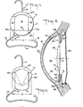
- the intraocular lens structure 10 includes as one of its elements a medial, light-focusing lens body or optical zone 12, FIG. 1.
- the lens body 12 may be constructed of any biologically inert, transparent material suitable for optical correction such as methylmethacrylate and other materials known in the art.
- Lens structure 10 is intended for insertion and fixation within an eye 30, after cataract removal.
- Eye 30 includes a cornea 31 having an endothelial layer 32.
- Anterior chamber 33 and posterior chamber 34 are defined by the position of iris 35.
- FIG. 3 shows eye 30 after an extra capsular surgical procedure in which, after the natural lens has been removed, a posterior capsule membrane 36, as well as a small part of anterior capsule 36a remains.
- Ciliary sulcus 38 of the posterior chamber is located between the sulcus of the capsule 36 and the iris 35.
- the term "adjacent the periphery of the iris", referring to seating, includes seating in the anterior chamber angle of the eye in the vicinity of the scleral spur 50, seating in the sulcus of the capsule 36, 36a, and seating in the ciliary sulcus 38.
- At least a pair of position fixation members 13, 17 are connected with the lens body 12 and extend from different peripheral regions of the lens body and are adapted to seat within an eye for fixing the position of the lens body within the eye.
- First position fixation member 13 has a first portion 14 contiguous to and extending generally laterally outwardly from a first region of the periphery of the lens body 12.
- First position fixation member 13 has a second portion 15 extending from the end of the first portion 14 generally transversely thereto and at least partly peripherally of the lens body 12 to provide two points of support for the lens in, for example, the anterior chamber of the eye.
- a knob 16 is fixed to the terminal end of portion 15 to prevent damage to human tissue within the eye.
- lens structure 10 includes a second position fixation member 17 as a necessary element thereof.
- Second member 17 includes a first portion 19 extending generally laterally outwardly from a second region of the periphery of the lens body 12 spaced from the first region and in a direction generally opposite to that of the first position fixation member 13 for extending to the periphery of the iris for seating in, for example, the anterior chamber angle 33' of the eye in the vicinity of the scleral spur 50, as represented in Fig. 3.
- First and second position fixation members 13, 17 may be molded integrally with lens body 12 or connected thereto by an adhesive, ultrasonic welding, fusion, or any other connection method known in the art. It should be noted that first and second position fixation members 13, 17 are constructed of biologically inert and nonabsorbative material such as methylmethacrylate, and the like. In the present embodiment first and second members 13, 17 are resilient or springy such that they will return toward the position shown in FIG. 1 after compression or extension away from the represented configuration.
- the lens body has at least one substantially rigid portion 61 and preferably has a circular periphery and has a plurality of separate portions, for example, three substantially rigid portions 60, 61, 62, in an initial relation preferably separated by a pair of cuts 63, 64, extending longitudinally across the lens body 12 to a bridging portion 65 of the lens body 12 connecting the plurality of portions 60, 61, 62.
- the small portions of the bridging portion 65, at the ends of the cuts 63, 64 are flexible so that the plurality of portions 60, 61, 62 may be overlapped upon the application of force thereto, as represented in Fig. 2.
- the bridging portion 65 is capable of returning the plurality of portions 60, 61, 62 substantially to their initial relation upon release of the force therefrom.
- the bridging portion 65 preferably is an outer edge of the lens body and may be thicker than the edge of the lens body over the major portion of the lens body to provide resilient strength.
- Each of the two outer portions 60, 62 of the lens body may have an aperture 70a, 71a therein adapted to receive a suture 73, represented in broken line construction in Fig. 1, for maintaining the three lens body portions 60, 61, 62 in a desired fixed relation to one another, which preferably is substantially their initial relation as represented in Fig. 1, when the lens is seated in the eye.
- each of the two outer portions 60, 62 may have a small lateral projection thereon (not shown) which projects across the cut 63 or 64 in the vicinity of where suture 73 is indicated into a corresponding lateral aperture in portion 61 for maintaining the three lens body portions 60, 61, 62 in substantially their initial relation, as represented in Fig. 1, when the lens is seated in the eye.
- the surgeon deforms the lens body as represented in Fig. 2.
- the width w of the lens body deformed as represented in Fig. 2 is much smaller than the diameter d of the lens body when undeformed as represented in Fig. 1.
- the position fixation members 13, 17 are shaped such that they can be snaked through the incision 42.
- the maximum transverse dimension corresponding to the width w of the deformed lens body 60, 61, 62 is represented in Fig. 2.
- the incision 42 therefore, needs to be only sufficiently long that the width w of the deformed lens body 60, 61', 62 represented in Fig.
- a pair of tweezers may be employed to stabilize and to steer the lens body 60, 61, 62 and first member 13 into seating engagement in the anterior chamber angle 33' .
- Second member 17 is then seated in the anterior chamber angle 33' for fixating the lens 10 in the anterior chamber.
- a suture 73 may be passed through apertures 70a, 71a as represented in Fig. 1 to maintain the lens body portions 60, 61, 62 in substantially their initial flat relation as represented in Figs 1 and 3.
- an intraocular lens 10 in accordance with the invention comprises a deformable lens body 12 which can be so deformed to a dimension w, as represented in Fig. 2, which is smaller than the maximum dimension d of the lens body 12 when undeformed, as represented in Fig. 1, that the lens body 12 can be inserted into the eye, when the lens body 12 is deformed, through a smaller opening in the eye than the opening through which the lens body 12 could be inserted when undeformed.
- the lens body 12 is capable of return to substantially its undeformed configuration after insertion into the eye.
- an intraocular lens 70 comprises a deformable lens body 71 which can be so deformed to a dimension which is smaller than the maximum dimension of the lens body 70 when undeformed, as represented in Fig. 4, that the lens body 71 can be inserted into the eye, when the lens body 71 is deformed, through a smaller opening in the eye than the opening through which the lens body 71 could be inserted when undeformed.
- the lens body 71 is capable of return to substantially its undeformed configuration after insertion into the eye.
- the lens body 71 preferably has a circular periphery with a diameter of, for example, 6 mm.
- the lens body 71 may, for example, be made of silicone rubber or an acrylate polymer (such as a terpolymer of 2-hydroxyethylmethacrylate, N-vinyl-2-pyrrolidone, and methacrylic acid, with ethyleneglycol dimethacrylate as a crosslinking agent) and, therefore, has a pliable, rubbery consistency.
- the silicone rubber material may, for example, be a hydroxydi- methylsilane which is optically clear, stable with good mechanical strength and highly elastic.
- the lens body 71 may be molded, glued or otherwise attached to a position-fixation member 72, preferably along a chord of the lens body 71.
- the position-fixation member 72 is of similar material to the Fig. 1 position-fixation members 13, 17 and is adapted to provide similar three- point fixation of the lens within the eye.
- the lens body 71 may be folded over as represented in Fig. 5 or folded in a curl as represented in Fig. 6 to a width of, for example, 3 mm or less. Since the position-fixation member 72 can be snaked through an opening in the eye of less than 2 mm, the curled dimension of the lens body will control the minimum size of incision required. Accordingly, an incision of only about 3 mm would be required.
- the lens body 71 is capable of return to substantially its undeformed configuration after insertion into the eye. It should be noted that the drawings, particularly Figs. 5 and 6, show the thickness of the folded lens body exaggerated for purposes of illustration.
- the lens body may be held in this folded condition by the instrument used by the surgeon for inserting the lens body through the incision, or a means such as a suture placed around the folded lens body may be used to maintain the lens body in folded condition during insertion. Such suture can be cut and removed once the lens body is within the eye.
- the lens body 70 has a free periphery along at least one region 73 generally parallel to the direction of the fold of the lens body 70 and has peripheral regions 74, 75 and 74a, 75a adjacent the opposite ends of the folds represented in Figs. 5 and 6 which are free of substantial impediment to folding the lens body along the folds.
- a position-fixation member 75 similar to the position-fixation member 72 but with a flexible loop 76 comprising, for example, a strand of plastic material such as Supramid, attached at two points of the member 72 which are preferably positioned on both sides of the center of the leg portion 79.
- the loop 76 preferably is generally elliptically shaped, with its major axis extending transverse to the leg portion 79. The flexibility of the loop 76 is such that it may be collapsed and inserted into the eye along with the leg portion 79 as the latter is inserted through the opening in the eye.
- the loop 76 is adapted to be connected inside the eye to a deformable lens body, for example as represented in Fig. 8, which is separately inserted into the eye.
- the lens body 80 of Fig. 8 can be so deformed, for example, in a manner similar to those represented in Figs. 5 and 6 for the lens body 71, to a dimension smaller than the maximum dimension of the lens body 80 when undeformed that the lens body 80 can be inserted into the eye, when the lens body is deformed, through a smaller opening in the eye than the opening through which the lens body could be inserted when undeformed.
- the lens body 80 is capable of return to substantially its undeformed configuration after insertion into the eye.
- the lens body 80 is of a material similar to the lens body 71 of Fig. 4, for example silicone rubber, so that it is pliable and bendable for passing through a small incision.
- the lens body 80 preferably has a circular periphery and is adapted for attachment inside the eye to the strand 76 of Fig. 7 by, for example, short prongs or hooks 81 extending from one face of the lens body near the periphery thereof.
- These prongs or hooks may be molded as part of the lens body or may be, for example, hook shaped inserts of platinum or the like.
- the prongs or hooks 81 preferably are disposed at the corners of an imaginary rectangle of greater length than height so that the hooks 81 will fit inside the elliptical loop 76 and the lens body 80 may be twisted relative to the loop 76 to force the hooks 81 into gripping engagement with the loop 76.
- one instrument may be inserted by the surgeon through the incision 42 in the eye (Fig. 2) while a second instrument may be inserted by the surgeon through a second very small incision which is ordinarily made in the eye for other purposes.
- a second instrument may be inserted by the surgeon through a second very small incision which is ordinarily made in the eye for other purposes.
- the surgeon can attach the lens body 80 to the loop 76 inside the eye as described.
- the lens body 80 has a free periphery along at least one region 82 generally parallel to the direction of the fold, represented by broken line 83 in Fig. 8, of the lens body 80 and has peripheral regions 84, 84a adjacent opposite ends of the fold which are free of substantial impediment to folding the lens body along the fold.
- the lens 85 there represented may, for example, have a substantially rigid lens body 86 of a material similar to the Fig. 1 lens body and may have position-fixation members 87, 88 similar to the corresponding members of the Fig. 1 embodiment.
- the lens body 86 has three separate portions a, b, c which are pivotably connected together by, for example, suitable hinges 89, each of which may, for example, comprise a plate 90 through which a pin 91 rotatably extends at one end and is attached to a lens body portion at the other end.
- the end portion a may be folded over the central portion b and the end portion c may be folded under the central portion b. Accordingly, .the position-fixation members 87, 88 can be snaked through the opening in the eye and the folded lens body 86 can be inserted into the eye through a smaller opening than the lens body 86 could be inserted when unfolded.
- the portions a, b, c of the lens body 86 can be unfolded to the condition represented in Fig. 9.
- Suitable lock pins 92, represented in broken-line construction in Fig. 9 can then be inserted into the lens body portions a, b, c to maintain them in fixed relationship. The surgeon may also use two instruments at the same time to unfold the lens body 86.
- the lens body 86 has a free periphery along regions 93, 94 generally parallel to the directions of the folds and has peripheral regions 95, 95a and 96, 96a adjacent opposite ends of the folds which are free of substantial impediment to folding the lens body along the folds.
- a lens constructed in accordance with the invention can be inserted into an eye through a smaller incision than the diameter of the undeformed lens body, thereby minimizing the risk of damage to the eye.
Landscapes
- Health & Medical Sciences (AREA)
- Ophthalmology & Optometry (AREA)
- Cardiology (AREA)
- Oral & Maxillofacial Surgery (AREA)
- Transplantation (AREA)
- Engineering & Computer Science (AREA)
- Biomedical Technology (AREA)
- Heart & Thoracic Surgery (AREA)
- Vascular Medicine (AREA)
- Life Sciences & Earth Sciences (AREA)
- Animal Behavior & Ethology (AREA)
- General Health & Medical Sciences (AREA)
- Public Health (AREA)
- Veterinary Medicine (AREA)
- Prostheses (AREA)
Applications Claiming Priority (2)
| Application Number | Priority Date | Filing Date | Title |
|---|---|---|---|
| US393057 | 1982-06-28 | ||
| US06/393,057 US4608049A (en) | 1982-06-28 | 1982-06-28 | Intraocular lens and method of inserting an intraocular lens into an eye |
Publications (3)
| Publication Number | Publication Date |
|---|---|
| EP0099641A2 true EP0099641A2 (de) | 1984-02-01 |
| EP0099641A3 EP0099641A3 (en) | 1984-11-14 |
| EP0099641B1 EP0099641B1 (de) | 1988-11-23 |
Family
ID=23553102
Family Applications (1)
| Application Number | Title | Priority Date | Filing Date |
|---|---|---|---|
| EP83303414A Expired EP0099641B1 (de) | 1982-06-28 | 1983-06-14 | Intraokularlinse |
Country Status (7)
| Country | Link |
|---|---|
| US (1) | US4608049A (de) |
| EP (1) | EP0099641B1 (de) |
| JP (1) | JPS5911846A (de) |
| BR (1) | BR8303197A (de) |
| CA (1) | CA1268903A (de) |
| DE (1) | DE3378520D1 (de) |
| MX (1) | MX154045A (de) |
Cited By (14)
| Publication number | Priority date | Publication date | Assignee | Title |
|---|---|---|---|---|
| JPS60250328A (ja) * | 1984-05-21 | 1985-12-11 | チヤ−ルズ デイ−.ケルマン | 眼内レンズ |
| US4657546A (en) * | 1983-07-08 | 1987-04-14 | Shearing Steven P | Intraocular lens |
| US4664665A (en) * | 1984-12-03 | 1987-05-12 | Precision-Cosmet Co., Inc. | Intraocular lens with foldable sides |
| EP0190056A3 (de) * | 1985-01-31 | 1987-05-20 | American Hospital Supply Corporation | Intraaugenlinse, die einen kleinen Einschnitt verlangt |
| US4704124A (en) * | 1985-01-22 | 1987-11-03 | Shearing Steven P | Intraocular lens |
| US4753653A (en) * | 1986-11-03 | 1988-06-28 | Precision-Cosmet Co., Inc. | Foldable bifocal intraocular lens |
| US4759763A (en) * | 1986-11-03 | 1988-07-26 | Precision-Cosmet Co., Inc. | Foldable intraocular lens |
| EP0319154A1 (de) * | 1987-12-04 | 1989-06-07 | Charles D. Kelman, M.D. | Zweiteilige intraokulare Linse |
| EP0226425A3 (en) * | 1985-12-09 | 1989-07-05 | Kenneth J. Hoffer | Multi-part intraocular lens and method of implanting it in an eye |
| EP0492126A3 (en) * | 1990-12-27 | 1993-02-17 | American Cyanamid Company | Composite intraocular lens and method of manufacture |
| EP1747769A3 (de) * | 2005-07-26 | 2007-04-04 | Visioncare Ophthalmic Technologies, Inc. | Intraokulare Vorrichtungen |
| US7727277B2 (en) | 2002-12-17 | 2010-06-01 | Visioncare Ophthalmic Technologies Inc. | Intraocular implants |
| US7918886B2 (en) | 2006-05-25 | 2011-04-05 | Visioncare Ophthalmic Technologies Inc. | Double insertion intraocular implant |
| US9949822B2 (en) | 1998-05-29 | 2018-04-24 | Johnson & Johnson Surgical Vision, Inc. | Intraocular lens for inhibiting cell growth and reducing glare |
Families Citing this family (56)
| Publication number | Priority date | Publication date | Assignee | Title |
|---|---|---|---|---|
| US4834754A (en) * | 1983-07-08 | 1989-05-30 | Shearing Steven P | Intraocular lens |
| US4725278A (en) * | 1985-01-22 | 1988-02-16 | Shearing Steven P | Intraocular lens |
| US4718906A (en) * | 1986-03-11 | 1988-01-12 | Mackool Richard J | Intraocular lens |
| US4950289A (en) * | 1986-11-03 | 1990-08-21 | Coopervision, Inc. | Small incision intraocular lens with adjustable refractive power |
| US4842601A (en) * | 1987-05-18 | 1989-06-27 | Smith S Gregory | Accommodating intraocular lens and method of implanting and using same |
| US5147394A (en) * | 1987-10-09 | 1992-09-15 | Siepser Steven B | High refractive index polymeric compositions suitable for use as expansile hydrogel intraocular lenses |
| US4888016A (en) * | 1988-02-10 | 1989-12-19 | Langerman David W | "Spare parts" for use in ophthalmic surgical procedures |
| US4878910A (en) * | 1988-06-13 | 1989-11-07 | Koziol Jeffrey E | Intraocular lens assembly |
| US5041134A (en) * | 1989-08-11 | 1991-08-20 | Donnell Francis E O | Intraocular lens assembly |
| US4955902A (en) * | 1989-11-13 | 1990-09-11 | Kelman Charles D | Decentered intraocular lens |
| US5026396A (en) * | 1990-05-07 | 1991-06-25 | Darin John J | Two-piece intraocular lens |
| US6692525B2 (en) | 1992-02-28 | 2004-02-17 | Advanced Medical Optics, Inc. | Intraocular lens |
| US5197981A (en) * | 1992-04-23 | 1993-03-30 | Alcon Surgical, Inc. | Intraocular lens having haptic of specific curvature and proportion |
| US5288293A (en) * | 1992-09-24 | 1994-02-22 | Donnell Jr Francis E O | In vivo modification of refractive power of an intraocular lens implant |
| US5366501A (en) * | 1993-05-12 | 1994-11-22 | Langerman David W | Intraocular lens with dual 360 degree haptics |
| US5578082A (en) * | 1994-05-27 | 1996-11-26 | Allergan | IOL for optimal capsular bag fit |
| US6488707B1 (en) * | 1997-08-20 | 2002-12-03 | Thinoptx, Inc. | Method of implanting a deformable intraocular corrective lens |
| US6786928B2 (en) | 1997-08-20 | 2004-09-07 | Thinoptx, Inc. | Small incision lens |
| US6800091B2 (en) | 1997-08-20 | 2004-10-05 | Thinoptx, Inc. | Method of using a small incision lens |
| US6517577B1 (en) * | 1998-05-28 | 2003-02-11 | Thinoptx, Inc. | Crossed haptics for intraocular lenses |
| FR2782912B1 (fr) * | 1998-09-07 | 2001-01-12 | Georges Baikoff | Implant intra-oculaire de chambre anterieure |
| ATE260306T1 (de) * | 1998-12-11 | 2004-03-15 | Biocompatibles Uk Ltd | Vernetzte polymere und refraktionsvorrichtung aus diesen geformt |
| US6171337B1 (en) * | 1999-03-31 | 2001-01-09 | Miles A. Galin | Positive power anterior chamber ocular implant |
| US7462194B1 (en) * | 2000-08-04 | 2008-12-09 | Blake Larry W | Two part “L”-shaped phakic IOL |
| US20060116765A1 (en) * | 2000-08-04 | 2006-06-01 | Blake Larry W | Refractive corrective lens (RCL) |
| US20020173846A1 (en) * | 2001-02-01 | 2002-11-21 | Larry Blake | Two part "L"- or "S"-shaped phakic IOL |
| US8460311B2 (en) | 2004-12-27 | 2013-06-11 | Hoya Corporation | Intraocular lens implanting device |
| WO2006080191A1 (ja) | 2005-01-26 | 2006-08-03 | Hoya Corporation | 眼内レンズ挿入用器具 |
| JP4836046B2 (ja) | 2005-02-24 | 2011-12-14 | Hoya株式会社 | 眼内レンズ挿入器具 |
| JP4922174B2 (ja) | 2005-09-28 | 2012-04-25 | Hoya株式会社 | 眼内レンズ挿入用器具 |
| JP4877643B2 (ja) | 2005-12-08 | 2012-02-15 | Hoya株式会社 | 眼内レンズ挿入用器具 |
| US8377125B2 (en) | 2006-04-05 | 2013-02-19 | Anew Optics, Inc. | Intraocular lens with accommodation |
| US8747465B2 (en) | 2007-05-30 | 2014-06-10 | Hoya Corporation | Intraocular lens insertion device |
| CN101677853B (zh) | 2007-05-30 | 2012-04-18 | Hoya株式会社 | 人工晶状体插入器具 |
| JP5086713B2 (ja) | 2007-07-11 | 2012-11-28 | Hoya株式会社 | 眼内レンズ挿入器具 |
| US8480734B2 (en) | 2007-12-27 | 2013-07-09 | Anew Optics, Inc. | Intraocular lens with accommodation |
| JP4932034B2 (ja) | 2008-03-28 | 2012-05-16 | パナソニック株式会社 | ソフトウェア更新装置、ソフトウェア更新システム、無効化方法、及び無効化プログラム |
| JP5254669B2 (ja) | 2008-06-05 | 2013-08-07 | Hoya株式会社 | 眼内レンズ挿入器具及びカートリッジ |
| JP5470753B2 (ja) | 2008-06-17 | 2014-04-16 | Hoya株式会社 | 眼内レンズ挿入器具 |
| JP5323420B2 (ja) | 2008-08-21 | 2013-10-23 | Hoya株式会社 | 眼内レンズ挿入器具 |
| JP5416379B2 (ja) | 2008-09-04 | 2014-02-12 | Hoya株式会社 | 眼内レンズ挿入器具 |
| US10010405B2 (en) | 2008-11-26 | 2018-07-03 | Anew Aol Technologies, Inc. | Haptic devices for intraocular lens |
| AU2009319753B2 (en) | 2008-11-26 | 2013-11-14 | Anew Iol Technologies, Inc. | Haptic devices for intraocular lens |
| WO2010079780A1 (ja) | 2009-01-07 | 2010-07-15 | Hoya株式会社 | 眼内レンズ挿入器具 |
| EP2397963A1 (de) | 2009-02-16 | 2011-12-21 | Panasonic Corporation | Manipulationsüberwachungsystem, kontrollverfahren und manipulationskontrollverfahren |
| JP5735531B2 (ja) | 2010-04-08 | 2015-06-17 | Hoya株式会社 | 眼内移植片挿入器具 |
| JP5744855B2 (ja) | 2010-04-26 | 2015-07-08 | パナソニック株式会社 | 改ざん監視システム、管理装置及び改ざん管理方法 |
| JP5511530B2 (ja) | 2010-06-10 | 2014-06-04 | Hoya株式会社 | 眼内レンズ挿入装置 |
| JPWO2017047714A1 (ja) | 2015-09-16 | 2018-07-05 | Hoya株式会社 | 眼内レンズ挿入器具 |
| JP6646987B2 (ja) | 2015-09-16 | 2020-02-14 | Hoya株式会社 | 眼内レンズ挿入器具 |
| US9956073B2 (en) | 2015-11-18 | 2018-05-01 | Verily Life Sciences Llc | Intraocular lens system with folding features |
| JP6998303B2 (ja) | 2016-06-28 | 2022-01-18 | Hoya株式会社 | 眼内レンズ挿入器 |
| EP3476375B1 (de) | 2016-06-28 | 2023-06-21 | Hoya Corporation | Werkzeug zum einsetzen einer intraokularlinse |
| JP7162443B2 (ja) | 2018-05-16 | 2022-10-28 | Hoya株式会社 | 容器付き眼内リング挿入器 |
| JP7162445B2 (ja) | 2018-05-25 | 2022-10-28 | Hoya株式会社 | 眼内レンズ挿入器 |
| JP7327956B2 (ja) | 2019-03-13 | 2023-08-16 | Hoya株式会社 | 眼内レンズ挿入器具 |
Family Cites Families (14)
| Publication number | Priority date | Publication date | Assignee | Title |
|---|---|---|---|---|
| US3711870A (en) * | 1971-12-07 | 1973-01-23 | R Deitrick | Artificial lens implant |
| JPS5338111B2 (de) * | 1974-11-14 | 1978-10-13 | ||
| DE2556665C3 (de) * | 1975-12-16 | 1978-08-03 | Titmus Eurocon Kontaktlinsen Kg, 8750 Aschaffenburg | Intraokulare künstliche Augenlinse |
| US4172297A (en) * | 1976-02-24 | 1979-10-30 | Inprohold Establishment | Artificial implant lens |
| US4056855A (en) * | 1976-04-07 | 1977-11-08 | Charles Kelman | Intraocular lens and method of implanting same |
| US4092743A (en) * | 1976-10-04 | 1978-06-06 | Kelman Charles D | Intraocular lenses |
| US4206518A (en) * | 1977-01-31 | 1980-06-10 | Fritz Jardon | Intraocular lens device |
| US4163608A (en) * | 1977-10-05 | 1979-08-07 | Neefe Charles W | Hydratable gas permeable methyl methacrylate copolymer |
| US4174543A (en) * | 1978-06-01 | 1979-11-20 | Kelman Charles D | Intraocular lenses |
| US4253199A (en) * | 1978-09-25 | 1981-03-03 | Surgical Design Corporation | Surgical method and apparatus for implants for the eye |
| US4254509A (en) * | 1979-04-09 | 1981-03-10 | Tennant Jerald L | Accommodating intraocular implant |
| US4373218A (en) * | 1980-11-17 | 1983-02-15 | Schachar Ronald A | Variable power intraocular lens and method of implanting into the posterior chamber |
| US4402579A (en) * | 1981-07-29 | 1983-09-06 | Lynell Medical Technology Inc. | Contact-lens construction |
| US4573998A (en) * | 1982-02-05 | 1986-03-04 | Staar Surgical Co. | Methods for implantation of deformable intraocular lenses |
-
1982
- 1982-06-28 US US06/393,057 patent/US4608049A/en not_active Expired - Lifetime
-
1983
- 1983-06-14 DE DE8383303414T patent/DE3378520D1/de not_active Expired
- 1983-06-14 EP EP83303414A patent/EP0099641B1/de not_active Expired
- 1983-06-16 BR BR8303197A patent/BR8303197A/pt unknown
- 1983-06-17 CA CA000430619A patent/CA1268903A/en not_active Expired
- 1983-06-27 MX MX197824A patent/MX154045A/es unknown
- 1983-06-27 JP JP58115748A patent/JPS5911846A/ja active Granted
Cited By (20)
| Publication number | Priority date | Publication date | Assignee | Title |
|---|---|---|---|---|
| US4657546A (en) * | 1983-07-08 | 1987-04-14 | Shearing Steven P | Intraocular lens |
| EP0165652A1 (de) * | 1984-05-21 | 1985-12-27 | Kelman, Charles D. | Intraokularlinse |
| JPS60250328A (ja) * | 1984-05-21 | 1985-12-11 | チヤ−ルズ デイ−.ケルマン | 眼内レンズ |
| US4664665A (en) * | 1984-12-03 | 1987-05-12 | Precision-Cosmet Co., Inc. | Intraocular lens with foldable sides |
| EP0186634A3 (en) * | 1984-12-03 | 1987-05-20 | Precision-Cosmet Co., Inc. | Intraocular lens with foldable sides |
| US4704124A (en) * | 1985-01-22 | 1987-11-03 | Shearing Steven P | Intraocular lens |
| EP0190056A3 (de) * | 1985-01-31 | 1987-05-20 | American Hospital Supply Corporation | Intraaugenlinse, die einen kleinen Einschnitt verlangt |
| US4743254A (en) * | 1985-01-31 | 1988-05-10 | American Hospital Supply Company | Small incision intraocular lens |
| EP0226425A3 (en) * | 1985-12-09 | 1989-07-05 | Kenneth J. Hoffer | Multi-part intraocular lens and method of implanting it in an eye |
| US4753653A (en) * | 1986-11-03 | 1988-06-28 | Precision-Cosmet Co., Inc. | Foldable bifocal intraocular lens |
| US4759763A (en) * | 1986-11-03 | 1988-07-26 | Precision-Cosmet Co., Inc. | Foldable intraocular lens |
| EP0319154A1 (de) * | 1987-12-04 | 1989-06-07 | Charles D. Kelman, M.D. | Zweiteilige intraokulare Linse |
| EP0492126A3 (en) * | 1990-12-27 | 1993-02-17 | American Cyanamid Company | Composite intraocular lens and method of manufacture |
| US5326506A (en) * | 1990-12-27 | 1994-07-05 | American Cyanamid Company | Method for making a composite intraocular lens |
| US9949822B2 (en) | 1998-05-29 | 2018-04-24 | Johnson & Johnson Surgical Vision, Inc. | Intraocular lens for inhibiting cell growth and reducing glare |
| US7727277B2 (en) | 2002-12-17 | 2010-06-01 | Visioncare Ophthalmic Technologies Inc. | Intraocular implants |
| US7736390B2 (en) | 2002-12-17 | 2010-06-15 | Visioncare Ophthalmic Technologies Inc. | Intraocular implants |
| US7776087B2 (en) | 2002-12-17 | 2010-08-17 | Visioncare Ophthalmic Technologies Inc. | Intraocular implants |
| EP1747769A3 (de) * | 2005-07-26 | 2007-04-04 | Visioncare Ophthalmic Technologies, Inc. | Intraokulare Vorrichtungen |
| US7918886B2 (en) | 2006-05-25 | 2011-04-05 | Visioncare Ophthalmic Technologies Inc. | Double insertion intraocular implant |
Also Published As
| Publication number | Publication date |
|---|---|
| MX154045A (es) | 1987-04-09 |
| DE3378520D1 (en) | 1988-12-29 |
| BR8303197A (pt) | 1984-01-31 |
| EP0099641B1 (de) | 1988-11-23 |
| US4608049A (en) | 1986-08-26 |
| JPH0356732B2 (de) | 1991-08-29 |
| JPS5911846A (ja) | 1984-01-21 |
| CA1268903A (en) | 1990-05-15 |
| EP0099641A3 (en) | 1984-11-14 |
Similar Documents
| Publication | Publication Date | Title |
|---|---|---|
| US4608049A (en) | Intraocular lens and method of inserting an intraocular lens into an eye | |
| US4911715A (en) | Overlapping two piece intraocular lens | |
| US4704123A (en) | Soft intraocular lens | |
| US6454801B1 (en) | Primary and supplemental intraocular lens system | |
| US4687484A (en) | Anterior chamber intraocular lens | |
| US4463458A (en) | Intraocular lens and implantation method | |
| US4174543A (en) | Intraocular lenses | |
| US10639142B2 (en) | Multicomponent intraocular lens | |
| US4404694A (en) | Intraocular lens | |
| US6241777B1 (en) | Phakic intraocular lenses | |
| US4617023A (en) | Intraocular lenses with openable haptic loops | |
| JP3249531B2 (ja) | 単一部品よりなる折りたたみ可能な眼内レンズ | |
| JP2538187B2 (ja) | 改善された支持部材を有する眼内レンズ | |
| EP0186634B1 (de) | Intraocularlinse mit umklappbaren Seitenteilen | |
| GB2111835A (en) | Intraocular lens | |
| JPS6051905B2 (ja) | 眼球内レンズ | |
| JPH08501715A (ja) | 補足眼内レンズ装置 | |
| WO2002011649A2 (en) | Two part 'l'-shaped phakic iol | |
| WO1998005273A1 (en) | Foldable intraocular lens | |
| US6488709B1 (en) | Intraocular lens implant | |
| EP0929273A1 (de) | Einsetzbare intraokulare lins | |
| US4664667A (en) | Deformable intraocular lens | |
| US6616693B1 (en) | Flexible fixation members for angle-supported anterior chamber intraocular lenses | |
| US4681586A (en) | Intraocular lens having unitary integral haptic means | |
| US4143427A (en) | Method and apparatus for accomplishing aphakic correction |
Legal Events
| Date | Code | Title | Description |
|---|---|---|---|
| PUAI | Public reference made under article 153(3) epc to a published international application that has entered the european phase |
Free format text: ORIGINAL CODE: 0009012 |
|
| AK | Designated contracting states |
Designated state(s): BE DE FR GB IT NL SE |
|
| PUAL | Search report despatched |
Free format text: ORIGINAL CODE: 0009013 |
|
| AK | Designated contracting states |
Designated state(s): BE DE FR GB IT NL SE |
|
| 17P | Request for examination filed |
Effective date: 19850507 |
|
| 17Q | First examination report despatched |
Effective date: 19860410 |
|
| D17Q | First examination report despatched (deleted) | ||
| ITF | It: translation for a ep patent filed | ||
| GRAA | (expected) grant |
Free format text: ORIGINAL CODE: 0009210 |
|
| AK | Designated contracting states |
Kind code of ref document: B1 Designated state(s): BE DE FR GB IT NL SE |
|
| REF | Corresponds to: |
Ref document number: 3378520 Country of ref document: DE Date of ref document: 19881229 |
|
| ET | Fr: translation filed | ||
| PLBE | No opposition filed within time limit |
Free format text: ORIGINAL CODE: 0009261 |
|
| STAA | Information on the status of an ep patent application or granted ep patent |
Free format text: STATUS: NO OPPOSITION FILED WITHIN TIME LIMIT |
|
| 26N | No opposition filed | ||
| PGFP | Annual fee paid to national office [announced via postgrant information from national office to epo] |
Ref country code: SE Payment date: 19900615 Year of fee payment: 8 |
|
| PGFP | Annual fee paid to national office [announced via postgrant information from national office to epo] |
Ref country code: NL Payment date: 19900630 Year of fee payment: 8 |
|
| PG25 | Lapsed in a contracting state [announced via postgrant information from national office to epo] |
Ref country code: SE Effective date: 19910615 |
|
| ITTA | It: last paid annual fee | ||
| PG25 | Lapsed in a contracting state [announced via postgrant information from national office to epo] |
Ref country code: NL Effective date: 19920101 |
|
| NLV4 | Nl: lapsed or anulled due to non-payment of the annual fee | ||
| EUG | Se: european patent has lapsed |
Ref document number: 83303414.3 Effective date: 19920109 |
|
| PGFP | Annual fee paid to national office [announced via postgrant information from national office to epo] |
Ref country code: BE Payment date: 19950626 Year of fee payment: 13 |
|
| PGFP | Annual fee paid to national office [announced via postgrant information from national office to epo] |
Ref country code: GB Payment date: 19950629 Year of fee payment: 13 |
|
| PG25 | Lapsed in a contracting state [announced via postgrant information from national office to epo] |
Ref country code: GB Effective date: 19960614 |
|
| PG25 | Lapsed in a contracting state [announced via postgrant information from national office to epo] |
Ref country code: BE Effective date: 19960630 |
|
| BERE | Be: lapsed |
Owner name: KELMAN CHARLES D. Effective date: 19960630 |
|
| GBPC | Gb: european patent ceased through non-payment of renewal fee |
Effective date: 19960614 |
|
| PGFP | Annual fee paid to national office [announced via postgrant information from national office to epo] |
Ref country code: FR Payment date: 20020610 Year of fee payment: 20 |
|
| PGFP | Annual fee paid to national office [announced via postgrant information from national office to epo] |
Ref country code: DE Payment date: 20020619 Year of fee payment: 20 |