EP0099656B1 - Kontaktapparat zum Stoffaustausch - Google Patents
Kontaktapparat zum Stoffaustausch Download PDFInfo
- Publication number
- EP0099656B1 EP0099656B1 EP83303622A EP83303622A EP0099656B1 EP 0099656 B1 EP0099656 B1 EP 0099656B1 EP 83303622 A EP83303622 A EP 83303622A EP 83303622 A EP83303622 A EP 83303622A EP 0099656 B1 EP0099656 B1 EP 0099656B1
- Authority
- EP
- European Patent Office
- Prior art keywords
- grid
- gas
- liquid
- vessel
- velocity
- Prior art date
- Legal status (The legal status is an assumption and is not a legal conclusion. Google has not performed a legal analysis and makes no representation as to the accuracy of the status listed.)
- Expired
Links
- 238000012546 transfer Methods 0.000 title description 3
- 239000007788 liquid Substances 0.000 claims description 92
- 239000007789 gas Substances 0.000 description 100
- 238000005201 scrubbing Methods 0.000 description 32
- 238000013461 design Methods 0.000 description 13
- 229910001868 water Inorganic materials 0.000 description 11
- 239000000356 contaminant Substances 0.000 description 9
- 238000010521 absorption reaction Methods 0.000 description 8
- XLYOFNOQVPJJNP-UHFFFAOYSA-N water Substances O XLYOFNOQVPJJNP-UHFFFAOYSA-N 0.000 description 8
- 239000007921 spray Substances 0.000 description 7
- 230000000694 effects Effects 0.000 description 6
- 238000006243 chemical reaction Methods 0.000 description 5
- 238000005243 fluidization Methods 0.000 description 5
- 238000012360 testing method Methods 0.000 description 5
- 238000013459 approach Methods 0.000 description 4
- 230000007423 decrease Effects 0.000 description 4
- 230000003068 static effect Effects 0.000 description 4
- 239000000463 material Substances 0.000 description 3
- 239000007787 solid Substances 0.000 description 3
- 238000006276 transfer reaction Methods 0.000 description 3
- 235000019738 Limestone Nutrition 0.000 description 2
- 238000005299 abrasion Methods 0.000 description 2
- 238000004140 cleaning Methods 0.000 description 2
- 238000002347 injection Methods 0.000 description 2
- 239000007924 injection Substances 0.000 description 2
- 230000003993 interaction Effects 0.000 description 2
- 239000006028 limestone Substances 0.000 description 2
- 238000000034 method Methods 0.000 description 2
- 238000002156 mixing Methods 0.000 description 2
- 239000002245 particle Substances 0.000 description 2
- 239000013618 particulate matter Substances 0.000 description 2
- 238000009420 retrofitting Methods 0.000 description 2
- 229920006395 saturated elastomer Polymers 0.000 description 2
- 239000002002 slurry Substances 0.000 description 2
- 230000001133 acceleration Effects 0.000 description 1
- 239000012159 carrier gas Substances 0.000 description 1
- 238000003889 chemical engineering Methods 0.000 description 1
- 239000003795 chemical substances by application Substances 0.000 description 1
- 239000000470 constituent Substances 0.000 description 1
- 238000011109 contamination Methods 0.000 description 1
- 238000010924 continuous production Methods 0.000 description 1
- 230000003247 decreasing effect Effects 0.000 description 1
- 238000010586 diagram Methods 0.000 description 1
- 238000004821 distillation Methods 0.000 description 1
- 238000009826 distribution Methods 0.000 description 1
- 238000001035 drying Methods 0.000 description 1
- 230000003628 erosive effect Effects 0.000 description 1
- 238000000605 extraction Methods 0.000 description 1
- 230000005484 gravity Effects 0.000 description 1
- 239000008240 homogeneous mixture Substances 0.000 description 1
- 238000009434 installation Methods 0.000 description 1
- 238000009533 lab test Methods 0.000 description 1
- 239000012263 liquid product Substances 0.000 description 1
- 230000014759 maintenance of location Effects 0.000 description 1
- 239000003595 mist Substances 0.000 description 1
- 239000000203 mixture Substances 0.000 description 1
- 239000000047 product Substances 0.000 description 1
- 238000012958 reprocessing Methods 0.000 description 1
- 230000000630 rising effect Effects 0.000 description 1
- 238000009991 scouring Methods 0.000 description 1
- 238000010561 standard procedure Methods 0.000 description 1
Images

Classifications
-
- B—PERFORMING OPERATIONS; TRANSPORTING
- B01—PHYSICAL OR CHEMICAL PROCESSES OR APPARATUS IN GENERAL
- B01J—CHEMICAL OR PHYSICAL PROCESSES, e.g. CATALYSIS OR COLLOID CHEMISTRY; THEIR RELEVANT APPARATUS
- B01J10/00—Chemical processes in general for reacting liquid with gaseous media other than in the presence of solid particles, or apparatus specially adapted therefor
-
- B—PERFORMING OPERATIONS; TRANSPORTING
- B01—PHYSICAL OR CHEMICAL PROCESSES OR APPARATUS IN GENERAL
- B01D—SEPARATION
- B01D3/00—Distillation or related exchange processes in which liquids are contacted with gaseous media, e.g. stripping
- B01D3/14—Fractional distillation or use of a fractionation or rectification column
- B01D3/16—Fractionating columns in which vapour bubbles through liquid
- B01D3/22—Fractionating columns in which vapour bubbles through liquid with horizontal sieve plates or grids; Construction of sieve plates or grids
-
- B—PERFORMING OPERATIONS; TRANSPORTING
- B01—PHYSICAL OR CHEMICAL PROCESSES OR APPARATUS IN GENERAL
- B01D—SEPARATION
- B01D47/00—Separating dispersed particles from gases, air or vapours by liquid as separating agent
- B01D47/12—Washers with plural different washing sections
-
- B—PERFORMING OPERATIONS; TRANSPORTING
- B01—PHYSICAL OR CHEMICAL PROCESSES OR APPARATUS IN GENERAL
- B01D—SEPARATION
- B01D53/00—Separation of gases or vapours; Recovering vapours of volatile solvents from gases; Chemical or biological purification of waste gases, e.g. engine exhaust gases, smoke, fumes, flue gases, aerosols
- B01D53/14—Separation of gases or vapours; Recovering vapours of volatile solvents from gases; Chemical or biological purification of waste gases, e.g. engine exhaust gases, smoke, fumes, flue gases, aerosols by absorption
- B01D53/18—Absorbing units; Liquid distributors therefor
-
- B—PERFORMING OPERATIONS; TRANSPORTING
- B01—PHYSICAL OR CHEMICAL PROCESSES OR APPARATUS IN GENERAL
- B01J—CHEMICAL OR PHYSICAL PROCESSES, e.g. CATALYSIS OR COLLOID CHEMISTRY; THEIR RELEVANT APPARATUS
- B01J19/00—Chemical, physical or physico-chemical processes in general; Their relevant apparatus
- B01J19/32—Packing elements in the form of grids or built-up elements for forming a unit or module inside the apparatus for mass or heat transfer
-
- B—PERFORMING OPERATIONS; TRANSPORTING
- B01—PHYSICAL OR CHEMICAL PROCESSES OR APPARATUS IN GENERAL
- B01J—CHEMICAL OR PHYSICAL PROCESSES, e.g. CATALYSIS OR COLLOID CHEMISTRY; THEIR RELEVANT APPARATUS
- B01J2219/00—Chemical, physical or physico-chemical processes in general; Their relevant apparatus
- B01J2219/32—Details relating to packing elements in the form of grids or built-up elements for forming a unit of module inside the apparatus for mass or heat transfer
- B01J2219/322—Basic shape of the elements
- B01J2219/32203—Sheets
- B01J2219/32206—Flat sheets
-
- B—PERFORMING OPERATIONS; TRANSPORTING
- B01—PHYSICAL OR CHEMICAL PROCESSES OR APPARATUS IN GENERAL
- B01J—CHEMICAL OR PHYSICAL PROCESSES, e.g. CATALYSIS OR COLLOID CHEMISTRY; THEIR RELEVANT APPARATUS
- B01J2219/00—Chemical, physical or physico-chemical processes in general; Their relevant apparatus
- B01J2219/32—Details relating to packing elements in the form of grids or built-up elements for forming a unit of module inside the apparatus for mass or heat transfer
- B01J2219/322—Basic shape of the elements
- B01J2219/32203—Sheets
- B01J2219/32237—Sheets comprising apertures or perforations
-
- B—PERFORMING OPERATIONS; TRANSPORTING
- B01—PHYSICAL OR CHEMICAL PROCESSES OR APPARATUS IN GENERAL
- B01J—CHEMICAL OR PHYSICAL PROCESSES, e.g. CATALYSIS OR COLLOID CHEMISTRY; THEIR RELEVANT APPARATUS
- B01J2219/00—Chemical, physical or physico-chemical processes in general; Their relevant apparatus
- B01J2219/32—Details relating to packing elements in the form of grids or built-up elements for forming a unit of module inside the apparatus for mass or heat transfer
- B01J2219/322—Basic shape of the elements
- B01J2219/32279—Tubes or cylinders
Definitions
- This invention relates to a mass transfer contact apparatus, for example a gas or liquid scrubber for removal of solid or liquid particles entrained in a gas stream and/or for removal of soluble gaseous constituents of a gas stream. It is also generally applicable to any like gas treatment operations which require basically an intimate contact between a gas and liquid. Such operations may include effecting heat exchange between gases and liquids in general; mass transfer; the drying of a liquid saturated or partially saturated gas stream by contact with a chilled liquid; stripping; distillation; and others.
- the internal structure is passive in the sense that it is not power driven and has few or no moving parts. (Those parts that do move do so under the influence of the gas or liquid moving through the vessel).
- Various kinds of structures have been employed, including bubble trays, packed columns, and grids.
- the design of the vessels must include process, operational and constructional considerations.
- the contact reaction must be effective and efficient from a quality (purity) and quantity (yield) point of view. Further, it must use energy supplied efficiently as well as accomplish the reaction with a minimum pressure drop.
- the apparatus should be simple and economical to build and easily cleaned and maintained. Further, vessel size is important. Desirably, the vessel should be as small and short as possible.
- gas-liquid contact apparatus produce good product quality and yield, at a good energy efficiency and low pressure drop; that it be practical and simple to construct and maintain; and that its size and the tower size be minimized while throughput capacity is maximized.
- US-A-3219324 and DE-C-1088927 each describe a gas-liquid contact apparatus comprising a housing member including a gas inlet and gas outlet, interconnecting ductwork between said inlet and outlet, at least one grid member within said ductwork, the grid member extending transversely to the direction of the flow of gas at said grid member and having an upwardly facing concave side, and means for dispensing a selected flow rate (L) of liquid onto said concave side of said grid member(s), in countercurrent to the flow of gas.
- a selected flow rate (L) of liquid onto said concave side of said grid member(s), in countercurrent to the flow of gas.
- each said grid member is a flexible grid freely suspended by its periphery.
- the grid member(s) has a cross-sectional profile which would equal the algebraic sum of the theoretical velocity pressure profile of the gas flowing in an open vessel and the static and dynamic heads of the contacting liquid. This is practically approximated by the free hanging catenary shaped grid described.
- An additional depth is preferably added to the grid, approximately 5 to 40% more, to create an energy imbalance in favour of the introduced liquid, thereby allowing it to drain.
- the grid members being made of flexible materials, facilitate cleaning.
- the grids can be arranged singularly, or in pairs separated by a predetermined distance. The latter arrangement provides further improved particulate removal. Grid members are effective with grid open areas upwards of 75% and even higher.
- the catenary shaped grid provides the least structural complexity in approximating the parabolic shape of the velocity pressure profile of the gas stream
- the desired grid shape can be approximated, e.g., through the use of a shallow cone or series of cones, or by a formed shape, with varying degrees of efficiency.
- a plurality of grid modules may be employed. Each of these modules is designed including a shaped grid or grid pair approximating the velocity pressure profile of the gas stream in each such that the net effect substantially approaches what would be achieved if the single grid or grid pair were suspended in the vessel.
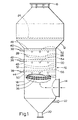
- Figure 1 shows a device 10 which includes a housing member 12 having an inlet and outlet, 14 and 16, for passing the contaminant gas. Between these is the scrubbing vessel 18 or ductwork.
- Items found on the vessel essentially unrelated to the present invention include a drain outlet 20; liquid connection 22 for recirculation purposes; and a chevron or mist eliminator 24.
- a plurality of grid members 26 to 36 Suspended within the vessel are a plurality of grid members 26 to 36. These are hung from the sides of the vessel by suitable means, not detailed, such as a circular rim piece.
- the grid members are orientated such that they are substantially perpendicular to the direction of gas flow.
- each grid pair positioned above each grid pair are means 38 for dispensing the scrubbing liquid onto the concave side of the upper grid member in each pair.
- the dispensing means include headers 40, 42 and 44 which are connected to a scrubbing liquid supply.
- Internal piping 46, 48 and 50 distribute the liquid to a plurality of, typically, low pressure (3.45x10 4 to 6.9x10 4 Pa, or 5-10 psig) nozzles, of open mixing design, including 52, 54 and 56. These dispense the liquid in droplet form across the breadth of the vessel, onto the upper surface of the top grid member 26, 30 and 34.
- a variety of liquid injection means can be employed since the method of liquid injection has little to do with the performance of the invention disclosed.
- the rate of absorption, impaction or interception varies across the diameter of the scrubber.
- the grid can be made of metallic or non-metallic, flexible materials. It can be preformed grid pressed into a shape approximating the velocity profile. Or, the shape required can be approximated through use of a shallow cone mesh or segments of cone meshes connected together to approximate the shape. A non-rigid grid can be mechanically flexed to facilitate cleaning, if necesasry. No internal beams or other structural members need be used.
- the net open area of the grid is selected to accommodate various conditions. For example, the open area will tend to be lower where it is necessary to conserve on the amount of scrubbing liquid to be used; to reduce abrasion of the grid member; or increase its structural strength (for large vessel spans). Conversely, it is desirable to have a greater open area where energy demands need to be restricted; or where large amounts of scrubbing liquid are employed (where gaseous contaminant concentrations are high); or to facilitate the drainage of scrubbing liquids containing higher percentages of solids, such as limestone slurry, or where dense particulate contamination is found. Generally, it has been found that the net open area normally runs between 50% and 75%, although an open area of the order of up to 85% to 90% has been used. However, at this high end, the performance of the grid scrubber approaches that of the conventional spray tower, with its attending problems.
- H SL and H DL are relatively constant across the vessel.
- the static head of the scrubbing liquid can be determined as follows:
- the increased depth can vary from 5% (for particulate-free gas) to 40% (for entrained particles), over the figure, d c , calculated above.
- FIG. 2 A schematic diagram depicting the liquid and gas interface around a single grid is shown in Figure 2.
- the scrubbing liquid 58 is shown being dispersed towards the interface from above. As noted earlier, it can be introduced onto the top surface 60 of the grid 62, in a variety of ways. This is not critical to the operation of the fluidized zone described hereinafter.
- the flowing gas is depicted as having a velocity pressure profile 64.
- a zone of high turbulence 66 is created on and below the grid.
- a gas-liquid contacting surface 68 results which is uniformly distributed above and across the top surface of the grid.
- this contact surface 68 there is also crafted a fluidized bed or zone in which droplets of the scrubbing liquid and randomly dispersed, contaminant gases efficiently interact.
- the height of the fluidized zone will be a function of the droplet size and the velocity of the gas. The higher the fluidized zone, the greater the gas absorption and particulate removal.
- the top surface of the zone, 72 is substantially flat as shown. With a shallower dish configuration, the centre area of the top surface rises up higher than the area near the vessel sides reflecting less dispersement of the gases towards the sidewall and less effective scrubbing of the gas. In fact, flow through of the gases can occur for dished grids which are too shallow.
- the liquid droplets in the fluidized zone will eventually collect and drain after a certain "operating" time in the zone. Drainage occurs primarily near the centre of the grid. The drained liquid collects in a sump below for extraction, reprocessing and reuse. Operating time of a droplet of liquid in the fluidized zone vary depending on many factors, and have been experimentally determined to be as high as 3 to 4 seconds.
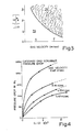
- Figure 3 reflects empirically derived data where UG is plotted against gas velocity for the catenary shaped grid.
- the area 76 above the curve reflects the various UG ratios for available gas velocities wherein the fluidization bed 70 results. Below the curve, in area 78, fluidization does not occur.
- an UG ratio is selected which will place the system's operation in zone 76.
- Figure 4 depicts various pressure drops for a single grid catenary scrubber at various gas velocities and liquid to gas ratios.
- gas velocities in the catenary scrubber can be higher than those in a typical spray tower scrubber.
- Gas velocities at the face of the grid of up to 6 m/sec (20 ft/sec) produced no irregularities.
- face velocities of upwards of 7.6 m/sec (25 ft/sec) are obtainable with a single grid.
- the higher gas velocities permit smaller, more economical towers thus saving initial investment expense and operating space.
- the upper grid 80 of similar shape to the lower grid 82 is positioned up to an empirically determined distance 84 above the lower grid. In theory there is no set minimum spacing between the two, since with the one grid physically on top of the other, the performance of the system would be as a single grid.
- the maximum distance 84 between the two will be a function of many variables including gas velocity, gas density and grid open area. For example, pilot test runs with a gas face-velocity of 9.1 m/sec (30 ft/sec) (higher velocities are possible with the grid pair); grid open area of 60%; and, a gas density of 1.2 kg/m 3 (0.075 lbs/ft 3 ), resulted in a maximum spacing of approximately 150 mm (six inches).
- the primary consequence which controls the spacing is the creation of a turbulent zone in the area 86 between the grids. If the grids are too far apart, the flowing gas is able to re-establish the velocity pressure profile that it presented as it approached the lower grid.
- the lower grid can be perceived as an energy dissipator.
- the random movement and reduced energy level of the gases in the zone 86 minimize the possibility of a turbulent zone immediately above the upper grid as is the case in a single grid arrangement.
- the scrubbing grid forms a film on the top surface of the upper grid, with movement, again, towards the centre of the vessel along paths 88.
- a fluidized bed or zone 90 is created in the volume immediately above the upper grid.
- the upper surface 92 of the fluidized zone 90 is substantially the same distance above the upper grid as in the case of the single grid approach.
- the fluidized zone is a controlled high density of scrubbing liquid per unit volume with enhanced iiquid-particulate interaction, and gas absorption through increased surface area of scrubbing liquid.
- the gas tends to redistribute itself towards the walls, as the liquid moves into the centre of the vessel.
- the liquid penetrates and drains through the upper grid into the turbulent zone 86 where further reaction between the gas and scrubbing agent takes place. Finally, the liquid penetrates the lower grid 82 and falls into the bottom of the vessel, from where it is processed or recirculated.
- the present design affords a very high turndown, i.e. the ratio of maximum tolerable gas flow to minimum gas flow, of three to one.
- the present invention may be used with a single or plurality of single grids; or, a single pair or plurality of pairs; or, a mixture of single grids and pairs, to provide the required degree of gas and/or particulate absorption.
- the design of the grid reflects the mirror image of the gas-velocity profile summed with the static and dynamic heads of scrubbing liquids, it is to be understood that grid shapes approximating this design (such as the catenary) and employing the teachings of this invention can be utilized with expectedly, varying degrees of success in improved absorption and particulate removal.
- the present design affords a degree of self-scouring because of liquid turbulence, a benefit where solids buildup can occur.
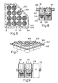
- FIGS. 6 to 10 depict the grid module approach employing the principles of the invention.
- FIG. 6 and Fig. 7 depict a quadrant or segment of a typical installation.
- a plurality of cylindrical modules such as module 100 are mounted on a plate 102 which includes a mounting flange 104 used to secure the plate to the vessel side walls or suspended plate support structure.
- Each module includes a housing 105 which is fabricated from suitable material based on the application.
- the housings typically run up to 600 mm (two feet) in length and can vary in diameter, e.g. 150, 200, 300, 450, 500, 600 mm (6", 8", 12", 18", 20", 24"), depending principally on the gas flow rate G in the vessel and the vessel diameter.
- the housings in a given vessel are uniform in length and diameter.
- the velocity profile of the gas flow for each module is empirically determined knowing the gas velocity in the unmodified vessel (i.e., without the module plates). Generally the gas flow rate in each module will be the gas flow rate in the unmodified vessel divided by the number of modules to be used.
- the design of the grid structure for the individual housings is based on the liquid and gas characteristics within each module, in accordance with the design criteria set forth above for a vessel grid structure.
- Fig. 8 depicts one way of introducing the liquid medium onto the concave side of the grid.
- the liquid 108 is dispensed onto the plate 110 to which the modules are secured.
- the liquid reaches the top 112 of the housing and spills over into the module towards the concave side of the upper grid structure 114.
- the entering gas stream 116 interacts with the liquid medium above the grid structure(s) -and the fluidized bed or zone 117 created, resulting in the desired mass transfer reaction between the two.
- the height of the housing walls above the grid(s) is sufficient to accommodate the height of the fluidized bed.
- the flow rate of the liquid cascading down onto the grid(s) will be a function of the rate at which the liquid is dispensed onto the plate 110, and must be at least sufficient to result in the controlled fluidization bed above the concave side of the grid for the gas velocity within the module. This again is in accordance with the design criteria discussed above.
- the liquid droplets in the fluidized bed eventually coalesce and drain down through the grids and into the bottom of the vessel where the liquid can be recovered, processed and then reused.
- Fig. 9 shows yet another embodiment depicting an alternative way of introducing the liquid medium above the grid structures.
- the liquid deposited on the plate 118 enters the module (e.g. 120) through openings such as 122 and 124.
- the height of the liquid on the plate is above the openings to provide a hydraulic seal.
- This grid module variation described consists of a grid or grid pair (or multiple grid or grid pairs) in a cylindrical housing.
- a square housing or similar configuration can likewise be employed.
Landscapes
- Chemical & Material Sciences (AREA)
- Chemical Kinetics & Catalysis (AREA)
- Organic Chemistry (AREA)
- Physics & Mathematics (AREA)
- Thermal Sciences (AREA)
- Engineering & Computer Science (AREA)
- Analytical Chemistry (AREA)
- General Chemical & Material Sciences (AREA)
- Oil, Petroleum & Natural Gas (AREA)
- Gas Separation By Absorption (AREA)
- Treating Waste Gases (AREA)
- Manufacture And Refinement Of Metals (AREA)
Claims (5)
Priority Applications (1)
| Application Number | Priority Date | Filing Date | Title |
|---|---|---|---|
| AT83303622T ATE46620T1 (de) | 1982-06-23 | 1983-06-23 | Kontaktapparat zum stoffaustausch. |
Applications Claiming Priority (4)
| Application Number | Priority Date | Filing Date | Title |
|---|---|---|---|
| US39113982A | 1982-06-23 | 1982-06-23 | |
| US391139 | 1982-06-23 | ||
| US06/496,054 US4432914A (en) | 1982-06-23 | 1983-05-19 | Mass transfer contact apparatus |
| US496054 | 1983-05-19 |
Publications (3)
| Publication Number | Publication Date |
|---|---|
| EP0099656A2 EP0099656A2 (de) | 1984-02-01 |
| EP0099656A3 EP0099656A3 (en) | 1986-11-20 |
| EP0099656B1 true EP0099656B1 (de) | 1989-09-27 |
Family
ID=27013414
Family Applications (1)
| Application Number | Title | Priority Date | Filing Date |
|---|---|---|---|
| EP83303622A Expired EP0099656B1 (de) | 1982-06-23 | 1983-06-23 | Kontaktapparat zum Stoffaustausch |
Country Status (5)
| Country | Link |
|---|---|
| US (1) | US4432914A (de) |
| EP (1) | EP0099656B1 (de) |
| KR (1) | KR900007320B1 (de) |
| CA (1) | CA1207225A (de) |
| DE (1) | DE3380620D1 (de) |
Families Citing this family (33)
| Publication number | Priority date | Publication date | Assignee | Title |
|---|---|---|---|---|
| USRE37499E1 (en) * | 1990-10-16 | 2002-01-08 | Sanyo Electric Co., Ltd | Apparatus for manufacturing carbonated water |
| US5593469A (en) * | 1995-12-08 | 1997-01-14 | Mec Systems, Inc. | Exhaust gas scrubber |
| US5861123A (en) * | 1996-04-26 | 1999-01-19 | Ceco Filters, Inc. | Ultraviolet light irradiated ebullating mass transfer system |
| JP3442974B2 (ja) * | 1997-07-30 | 2003-09-02 | 本田技研工業株式会社 | 吸収式冷凍機の精留装置 |
| US6007055A (en) * | 1997-12-29 | 1999-12-28 | Schifftner; Kenneth C. | Gas and liquid contact apparatus |
| RU2134150C1 (ru) * | 1998-04-07 | 1999-08-10 | Кубанский государственный технологический университет | Циклонный скруббер |
| AT2941U1 (de) * | 1998-05-06 | 1999-07-26 | Fleischhacker Gerhard | Flexible flüssigkeitssperre |
| US6451268B1 (en) * | 1999-04-16 | 2002-09-17 | Minerals Technologies Inc. | Method and apparatus for continuous gas liquid reactions |
| TW579630B (en) | 2001-03-28 | 2004-03-11 | Qualcomm Inc | Method and apparatus for power control for point-to-multipoint services in a communication system |
| JP2005535237A (ja) * | 2002-08-01 | 2005-11-17 | インターディジタル テクノロジー コーポレイション | ポイントツーマルチポイント物理チャネルの電力制御 |
| US7716146B2 (en) * | 2006-12-22 | 2010-05-11 | Verizon Patent And Licensing Inc. | Network management system utilizing a neural network |
| US8425665B2 (en) * | 2007-01-19 | 2013-04-23 | Heartland Technology Partners, Llc | Fluid scrubber |
| US8136797B2 (en) * | 2007-01-19 | 2012-03-20 | Heartland Technology Partners, Llc | Cooling tower |
| US8382075B2 (en) * | 2007-01-19 | 2013-02-26 | Heartland Technology Partners, Llc | Air stripper |
| US7832714B2 (en) | 2007-01-19 | 2010-11-16 | Heartland Technology Partners Llc | Desalination system |
| US8801897B2 (en) * | 2007-03-13 | 2014-08-12 | Heartland Technology Partners Llc | Compact wastewater concentrator and contaminant scrubber |
| US8679291B2 (en) * | 2007-03-13 | 2014-03-25 | Heartland Technology Partners Llc | Compact wastewater concentrator using waste heat |
| US8790496B2 (en) * | 2007-03-13 | 2014-07-29 | Heartland Technology Partners Llc | Compact wastewater concentrator and pollutant scrubber |
| US10005678B2 (en) | 2007-03-13 | 2018-06-26 | Heartland Technology Partners Llc | Method of cleaning a compact wastewater concentrator |
| US20100176042A1 (en) * | 2007-03-13 | 2010-07-15 | Duesel Jr Bernard F | Wastewater Concentrator |
| US8741100B2 (en) | 2007-03-13 | 2014-06-03 | Heartland Technology Partners Llc | Liquid concentrator |
| CA2751720C (en) | 2009-02-12 | 2018-04-10 | Heartland Technology Partners Llc | Compact wastewater concentrator using waste heat |
| US9014339B2 (en) | 2010-10-27 | 2015-04-21 | American Science And Engineering, Inc. | Versatile x-ray beam scanner |
| US8721771B2 (en) | 2011-01-21 | 2014-05-13 | Heartland Technology Partners Llc | Condensation plume mitigation system for exhaust stacks |
| US9296624B2 (en) | 2011-10-11 | 2016-03-29 | Heartland Technology Partners Llc | Portable compact wastewater concentrator |
| US8808497B2 (en) | 2012-03-23 | 2014-08-19 | Heartland Technology Partners Llc | Fluid evaporator for an open fluid reservoir |
| US8741101B2 (en) | 2012-07-13 | 2014-06-03 | Heartland Technology Partners Llc | Liquid concentrator |
| US8585869B1 (en) | 2013-02-07 | 2013-11-19 | Heartland Technology Partners Llc | Multi-stage wastewater treatment system |
| US9199861B2 (en) | 2013-02-07 | 2015-12-01 | Heartland Technology Partners Llc | Wastewater processing systems for power plants and other industrial sources |
| CN110302582B (zh) * | 2018-07-27 | 2021-08-03 | 安徽金三隆再生资源有限公司 | 一种洗涤塔的循环水自净结构与工艺 |
| US20200376406A1 (en) | 2019-05-31 | 2020-12-03 | Heartland Technology Partners Llc. | Harmful substance removal system and method |
| US11193898B1 (en) | 2020-06-01 | 2021-12-07 | American Science And Engineering, Inc. | Systems and methods for controlling image contrast in an X-ray system |
| FR3114381B1 (fr) * | 2020-09-18 | 2023-02-24 | Univ De Chambery Univ Savoie Mont Blanc | Échangeur de sorption |
Family Cites Families (17)
| Publication number | Priority date | Publication date | Assignee | Title |
|---|---|---|---|---|
| FR335803A (fr) * | 1903-09-19 | 1904-02-15 | Louis Valette | Laveur à gaz |
| US774207A (en) * | 1904-05-12 | 1904-11-08 | Alfred Steinbart | Gas-scrubber. |
| FR613424A (fr) * | 1925-05-27 | 1926-11-17 | Appareil pour la séparation des éléments liquides contenus dans les vapeurs ou dans les gaz | |
| US1986736A (en) * | 1934-04-09 | 1935-01-01 | James L Mauthe | Gas washer |
| FR899222A (fr) * | 1942-08-12 | 1945-05-24 | Gewerkschaft Keramchemie Berggarten Siershahn Westerwald | Tour d'arrosage pour le lavage de gaz |
| US2458909A (en) * | 1947-04-22 | 1949-01-11 | Harry J John | Spray trap |
| US3036417A (en) * | 1959-03-06 | 1962-05-29 | Airfilpat Holdings Proprietary | Gas scrubbing and like operations |
| US3219324A (en) * | 1960-08-01 | 1965-11-23 | Universal Oil Prod Co | Apparatus for interphase contact between fluids |
| US3395656A (en) * | 1967-01-30 | 1968-08-06 | Steelcraft Corp | Flyash removal device for incinerators |
| US3739551A (en) * | 1970-11-16 | 1973-06-19 | Norton Co | Method of gas absorption and apparatus therefor |
| US3761064A (en) * | 1970-12-30 | 1973-09-25 | Andco Inc | Gas scrubber |
| US3765659A (en) * | 1972-01-17 | 1973-10-16 | B Reilly | Gas scrubber |
| US3892837A (en) * | 1972-07-25 | 1975-07-01 | Fuji Kasui Eng Co Ltd | Process for removing sulfur oxides from gases |
| US3795486A (en) * | 1973-02-22 | 1974-03-05 | Environeering | Wet scrubber |
| US3969447A (en) * | 1973-10-18 | 1976-07-13 | Fritz W. Glitsch & Sons, Inc. | Grids for fluid contact apparatus |
| SU718687A1 (ru) * | 1978-08-30 | 1980-02-29 | Специализированное Конструкторско-Технологическое Бюро "Энергопромполимер" | Градирн |
| GB2053720A (en) * | 1979-06-08 | 1981-02-11 | Davy Int Oil & Chemi | Distillation tray |
-
1983
- 1983-05-19 US US06/496,054 patent/US4432914A/en not_active Expired - Lifetime
- 1983-06-22 CA CA000430907A patent/CA1207225A/en not_active Expired
- 1983-06-23 KR KR1019830002823A patent/KR900007320B1/ko not_active Expired
- 1983-06-23 DE DE8383303622T patent/DE3380620D1/de not_active Expired
- 1983-06-23 EP EP83303622A patent/EP0099656B1/de not_active Expired
Also Published As
| Publication number | Publication date |
|---|---|
| US4432914A (en) | 1984-02-21 |
| DE3380620D1 (en) | 1989-11-02 |
| EP0099656A2 (de) | 1984-02-01 |
| KR900007320B1 (ko) | 1990-10-08 |
| KR840004872A (ko) | 1984-10-31 |
| EP0099656A3 (en) | 1986-11-20 |
| CA1207225A (en) | 1986-07-08 |
Similar Documents
| Publication | Publication Date | Title |
|---|---|---|
| EP0099656B1 (de) | Kontaktapparat zum Stoffaustausch | |
| US3997303A (en) | Liquid-gas phase separator having a perforated plate and mist eliminator pad | |
| US4263021A (en) | Gas-liquid contact system | |
| US5535989A (en) | Liquid film producing process and apparatus for fluid-liquid contacting | |
| EP0542918B1 (de) | Flüssigkeitsverteiler für gaz-flüssigkeitkontaktapparat | |
| CA2446171C (en) | Flue gas desulfurization system with a stepped tray | |
| EP0510275B1 (de) | Gas-Flüssig-Kontaktapparat und Verfahren zum Gas-Flüssig-Kontakt | |
| JP3523865B2 (ja) | ガス浄化法またはガス冷却法および装置 | |
| JPH0554365B2 (de) | ||
| CA2284582A1 (en) | Co-current contacting separation tray design and methods for using same | |
| HU206053B (en) | Method and apparatus for purifying gas from solid, fluid and/or gaseous contaminations | |
| US4601731A (en) | Chevron-type mist eliminator and method | |
| US4361469A (en) | Process for using cocurrent contacting distillation columns | |
| JP2001506913A (ja) | 化学プロセス塔の脱エントレインメント・アセンブリ | |
| JPS63503522A (ja) | 物質移動装置 | |
| RO117765B1 (ro) | Procedeu de curăţare umedă a gazelor de ardere | |
| US3969094A (en) | Flue gas scrubber | |
| US6032932A (en) | Packing grates for wet gas scrubber and other applications | |
| US3589689A (en) | Vapor-liquid contact process | |
| US3733061A (en) | Gas-liquid contact apparatus | |
| EP0640373B1 (de) | Sprühturm und Verfahren zur Kühlung, Befeuchtung und/oder Reinigung von Gas | |
| US5527496A (en) | Spray header integrated tray | |
| EP1096992B1 (de) | Zyklon zum kontaktieren von dampf/flüssigkeit mit einrichtung zum verbinden des rückmischens | |
| US5439510A (en) | High-velocity, high-capacity mist eliminator assembly and method | |
| US3440803A (en) | Gas scrubber |
Legal Events
| Date | Code | Title | Description |
|---|---|---|---|
| PUAI | Public reference made under article 153(3) epc to a published international application that has entered the european phase |
Free format text: ORIGINAL CODE: 0009012 |
|
| AK | Designated contracting states |
Designated state(s): AT BE CH DE FR GB IT LI LU NL SE |
|
| PUAL | Search report despatched |
Free format text: ORIGINAL CODE: 0009013 |
|
| AK | Designated contracting states |
Kind code of ref document: A3 Designated state(s): AT BE CH DE FR GB IT LI LU NL SE |
|
| 17P | Request for examination filed |
Effective date: 19861023 |
|
| 17Q | First examination report despatched |
Effective date: 19870506 |
|
| GRAA | (expected) grant |
Free format text: ORIGINAL CODE: 0009210 |
|
| RAP1 | Party data changed (applicant data changed or rights of an application transferred) |
Owner name: OTTO H. YORK COMPANY, INC. |
|
| ITF | It: translation for a ep patent filed | ||
| AK | Designated contracting states |
Kind code of ref document: B1 Designated state(s): AT BE CH DE FR GB IT LI LU NL SE |
|
| REF | Corresponds to: |
Ref document number: 46620 Country of ref document: AT Date of ref document: 19891015 Kind code of ref document: T |
|
| REF | Corresponds to: |
Ref document number: 3380620 Country of ref document: DE Date of ref document: 19891102 |
|
| ET | Fr: translation filed | ||
| PLBE | No opposition filed within time limit |
Free format text: ORIGINAL CODE: 0009261 |
|
| STAA | Information on the status of an ep patent application or granted ep patent |
Free format text: STATUS: NO OPPOSITION FILED WITHIN TIME LIMIT |
|
| 26N | No opposition filed | ||
| ITTA | It: last paid annual fee | ||
| PGFP | Annual fee paid to national office [announced via postgrant information from national office to epo] |
Ref country code: FR Payment date: 19930609 Year of fee payment: 11 |
|
| PGFP | Annual fee paid to national office [announced via postgrant information from national office to epo] |
Ref country code: SE Payment date: 19930614 Year of fee payment: 11 Ref country code: AT Payment date: 19930614 Year of fee payment: 11 |
|
| PGFP | Annual fee paid to national office [announced via postgrant information from national office to epo] |
Ref country code: CH Payment date: 19930628 Year of fee payment: 11 |
|
| PGFP | Annual fee paid to national office [announced via postgrant information from national office to epo] |
Ref country code: NL Payment date: 19930630 Year of fee payment: 11 |
|
| PGFP | Annual fee paid to national office [announced via postgrant information from national office to epo] |
Ref country code: LU Payment date: 19930719 Year of fee payment: 11 |
|
| PGFP | Annual fee paid to national office [announced via postgrant information from national office to epo] |
Ref country code: BE Payment date: 19930803 Year of fee payment: 11 |
|
| EPTA | Lu: last paid annual fee | ||
| PG25 | Lapsed in a contracting state [announced via postgrant information from national office to epo] |
Ref country code: LU Free format text: LAPSE BECAUSE OF NON-PAYMENT OF DUE FEES Effective date: 19940623 Ref country code: AT Effective date: 19940623 |
|
| PG25 | Lapsed in a contracting state [announced via postgrant information from national office to epo] |
Ref country code: SE Effective date: 19940624 |
|
| PG25 | Lapsed in a contracting state [announced via postgrant information from national office to epo] |
Ref country code: LI Effective date: 19940630 Ref country code: CH Effective date: 19940630 Ref country code: BE Effective date: 19940630 |
|
| BERE | Be: lapsed |
Owner name: OTTO H. YORK CY INC. Effective date: 19940630 |
|
| PG25 | Lapsed in a contracting state [announced via postgrant information from national office to epo] |
Ref country code: NL Effective date: 19950101 |
|
| EUG | Se: european patent has lapsed |
Ref document number: 83303622.1 Effective date: 19950110 |
|
| NLV4 | Nl: lapsed or anulled due to non-payment of the annual fee | ||
| PG25 | Lapsed in a contracting state [announced via postgrant information from national office to epo] |
Ref country code: FR Effective date: 19950228 |
|
| REG | Reference to a national code |
Ref country code: CH Ref legal event code: PL |
|
| EUG | Se: european patent has lapsed |
Ref document number: 83303622.1 |
|
| REG | Reference to a national code |
Ref country code: FR Ref legal event code: ST |
|
| REG | Reference to a national code |
Ref country code: GB Ref legal event code: 732E |
|
| PGFP | Annual fee paid to national office [announced via postgrant information from national office to epo] |
Ref country code: DE Payment date: 19980625 Year of fee payment: 16 |
|
| PG25 | Lapsed in a contracting state [announced via postgrant information from national office to epo] |
Ref country code: DE Free format text: LAPSE BECAUSE OF NON-PAYMENT OF DUE FEES Effective date: 20000503 |
|
| PGFP | Annual fee paid to national office [announced via postgrant information from national office to epo] |
Ref country code: GB Payment date: 20010502 Year of fee payment: 19 |
|
| REG | Reference to a national code |
Ref country code: GB Ref legal event code: IF02 |
|
| PG25 | Lapsed in a contracting state [announced via postgrant information from national office to epo] |
Ref country code: GB Free format text: LAPSE BECAUSE OF NON-PAYMENT OF DUE FEES Effective date: 20020623 |
|
| GBPC | Gb: european patent ceased through non-payment of renewal fee |
Effective date: 20020623 |