EP0099663A2 - Dispositif de concentration et de chauffage à énergie solaire - Google Patents
Dispositif de concentration et de chauffage à énergie solaire Download PDFInfo
- Publication number
- EP0099663A2 EP0099663A2 EP83303692A EP83303692A EP0099663A2 EP 0099663 A2 EP0099663 A2 EP 0099663A2 EP 83303692 A EP83303692 A EP 83303692A EP 83303692 A EP83303692 A EP 83303692A EP 0099663 A2 EP0099663 A2 EP 0099663A2
- Authority
- EP
- European Patent Office
- Prior art keywords
- fluid
- solar energy
- incident
- transmissive material
- absorbing
- Prior art date
- Legal status (The legal status is an assumption and is not a legal conclusion. Google has not performed a legal analysis and makes no representation as to the accuracy of the status listed.)
- Ceased
Links
Images


Classifications
-
- F—MECHANICAL ENGINEERING; LIGHTING; HEATING; WEAPONS; BLASTING
- F24—HEATING; RANGES; VENTILATING
- F24S—SOLAR HEAT COLLECTORS; SOLAR HEAT SYSTEMS
- F24S23/00—Arrangements for concentrating solar-rays for solar heat collectors
- F24S23/10—Prisms
-
- F—MECHANICAL ENGINEERING; LIGHTING; HEATING; WEAPONS; BLASTING
- F24—HEATING; RANGES; VENTILATING
- F24S—SOLAR HEAT COLLECTORS; SOLAR HEAT SYSTEMS
- F24S60/00—Arrangements for storing heat collected by solar heat collectors
- F24S60/30—Arrangements for storing heat collected by solar heat collectors storing heat in liquids
-
- F—MECHANICAL ENGINEERING; LIGHTING; HEATING; WEAPONS; BLASTING
- F24—HEATING; RANGES; VENTILATING
- F24S—SOLAR HEAT COLLECTORS; SOLAR HEAT SYSTEMS
- F24S20/00—Solar heat collectors specially adapted for particular uses or environments
- F24S2020/10—Solar modules layout; Modular arrangements
- F24S2020/18—Solar modules layout; Modular arrangements having a particular shape, e.g. prismatic, pyramidal
-
- Y—GENERAL TAGGING OF NEW TECHNOLOGICAL DEVELOPMENTS; GENERAL TAGGING OF CROSS-SECTIONAL TECHNOLOGIES SPANNING OVER SEVERAL SECTIONS OF THE IPC; TECHNICAL SUBJECTS COVERED BY FORMER USPC CROSS-REFERENCE ART COLLECTIONS [XRACs] AND DIGESTS
- Y02—TECHNOLOGIES OR APPLICATIONS FOR MITIGATION OR ADAPTATION AGAINST CLIMATE CHANGE
- Y02B—CLIMATE CHANGE MITIGATION TECHNOLOGIES RELATED TO BUILDINGS, e.g. HOUSING, HOUSE APPLIANCES OR RELATED END-USER APPLICATIONS
- Y02B10/00—Integration of renewable energy sources in buildings
- Y02B10/20—Solar thermal
-
- Y—GENERAL TAGGING OF NEW TECHNOLOGICAL DEVELOPMENTS; GENERAL TAGGING OF CROSS-SECTIONAL TECHNOLOGIES SPANNING OVER SEVERAL SECTIONS OF THE IPC; TECHNICAL SUBJECTS COVERED BY FORMER USPC CROSS-REFERENCE ART COLLECTIONS [XRACs] AND DIGESTS
- Y02—TECHNOLOGIES OR APPLICATIONS FOR MITIGATION OR ADAPTATION AGAINST CLIMATE CHANGE
- Y02E—REDUCTION OF GREENHOUSE GAS [GHG] EMISSIONS, RELATED TO ENERGY GENERATION, TRANSMISSION OR DISTRIBUTION
- Y02E10/00—Energy generation through renewable energy sources
- Y02E10/40—Solar thermal energy, e.g. solar towers
Definitions
- the present invention relates to solar energy utilization apparatus generally and more particularly to a solar energy powered water heater.
- Solar energy concentrators are also known. Examples of such concentrators are described in U.S. Patents 4,162,824; 4,141,340; 4,069,812; 4,154,219; 4,056,094; 4,045,246; 4,024,852; and 4,003,364 and in German Offenlegungsschrift 2,827,708.
- the present invention seeks to provide an improved solar energy concentrating collector which is particularly useful for water heating applications.
- the transmissive material is integrally formed as a single unit defining a central bore in which the plate is located and which defines the fluid channel.
- the transmissive material is formed of two identical halves, each of a generally triangular configuration.
- each of the identical halves has an incident surface of width between one and two inches and the plates have absorbing surfaces of less than one inch.
- the incident radiation includes diffuse radiation.
- the concentration apparatus also comprises reflectors associated with a surface of the transmissive material for directing radiation towards the absorbing surface.
- the incident surface defines at least one surface which is generally transparent to incident solar radiation from the atmosphere and substantially reflective of radiation reflected within the transmissive material.
- the present invention also seeks to provide an improved solar water heater, which according to a preferred embodiment, employs a concentrator of the type described hereinabove. ..
- a solar water heater comprising a housing, apparatus disposed in the housing for receiving incident solar energy and for heating a first fluid thereby, heat exchanger apparatus disposed in the housing and receiving the heated first fluid and being operative to heat a second fluid, and apparatus for providing circulation of the first fluid through the heating and heat exchanger apparatus, and wherein the first fluid is maintained at atmospheric pressure.
- the receiving and heating apparatus comprises a solar energy concentrator.
- the heat exchanger apparatus comprises a zig-zag arrangement of welded thermally conductive tubes and fins through which passes a pressurized flow of said second fluid.
- the housing is integrally formed of an insulating material such as a foamed plastic.
- the second fluid is normally heated as it passes through the heat exchanger and is not stored in a heated state.
- a highly efficient collector is employed to provide a moderate temperature water heater output, typically 40 degrees centigrade, even under conditions of relatively low incident solar radiation, thus providing a solar water heater which provides usable hot water in required quantities during a great majority of the days of the year.
- FIG. 1 - 3 illustrate a preferred embodiment of the present invention.
- Element 10 typically comprises a material having an index of refraction greater than that of air and is typically formed of glass or of a generally clear plastic such as polycarbonate.
- element 10 comprises a unitary integrally formed element which is formed with an elongate bore 12 of generally uniform rounded rectangular cross section.
- a solar energy absorber plate 14 Disposed in bore 12 is a solar energy absorber plate 14, which typically comprises a strip of metal such as copper or of any other suitable material having opposite elongate side surfaces 16, each of which is preferably provided with a solar energy selective coating, providing low emissivity and high absorptivity.
- the selective coating may be one of a number of known selective coatings and may comprise, for example, black paint or a nickel oxide coating.
- Solar energy absorbing surfaces 16 are normally disposed in spaced relationship to the inner adjacent walls 18 of bore 12, along at least most of the area thereof, with the possible exception of areas adjacent the top and bottom edges of plate 14.
- the volume thus defined between each of the surfaces 16 and the respective adjacent walls 18 provides a pair of channels 20, which may or may not be in communication with each other, for the passage of heat transfer fluid through bore 12 in thermal communication with surfaces 16.
- the purpose of the passage of this heat transfer fluid is to receive heat absorbed by surfaces 16 and to transfer it to utilization apparatus, one example of which will be described hereinbelow.
- the heat transfer fluid may be any desired fluid and may be, for example, water, oil, or any other suitable fluid. Circulation of the fluid may be produced by thermosyphonic action or by means of a pump or any other suitable driving means.
- element 10 may be formed of two half elements 22, each having the configuration illustrated in Fig. 3A.
- Half elements 22 may be joined at their respective seams 24 and 26 by adhesive, ultrasonic welding or any other suitable bonding means for providing the element 10 shown in Figs. 1 and 2.
- elements 10 may comprise generally triangular elements 27 which may be joined by first and second transparent elongate bridge members 29 which define bore 12.
- a plurality of elements 10 may be formed together in an array, such as a sheet like arrangement.
- Element 10 defines symmetrical generally triangular total internal reflection elements 30 and 32 each operating with one of the two solar absorbing surfaces 16.
- Each element 30, 32 defines an incident surface 34 which is arranged to lie , . perpendicular to surface 16 and to have a surface area greater than the surface area of surface 16.
- Each element 30 also defines a reflective surface 38, which may be provided by a mirror or by a reflective coating, as necessary.
- Typical cross sectional dimensions of the apparatus of Figs. 1 - 8 are as follows:
- the solar absorbing plate 14 is substantially surrounded by element 10, thus providing thermal insulation to plate 14.
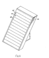
- the water heater comprises a housing 40, preferably formed of a foamed plastic material such as foamed polyeurethane or alternatively formed of cross linked polyethylene.
- the housing defines a forward recess 42 in which is disposed a solar concentrator array 44.
- Solar concentrator array 44 is preferably an array of the general type described hereinabove in connection with Figs 1 - 3B.
- first and second side manifolds 46 Disposed in housing 40 on both ends of array 44 are first and second side manifolds 46 which couple the fluid flow paths in the individual elements 48 of array 44 in parallel for providing a fluid path for a first fluid, such as oil or a water solution, to be heated by the solar concentrator array 44.
- One of manifolds 46 communicates at the bottom thereof via a water inlet 50 with the bottom region of a reservoir 52 which contains the first fluid under atmospheric pressure.
- the other one of the manifolds 46 most of which is not seen in Figs. 5 and 6, communicates at the top thereof via a circulation conduit 54 and a circulation pump 56 with the top region of reservoir 52.
- Heat exchanger 55 Disposed in reservoir 52 is a heat exchanger 55, through which flows a second fluid to be heated by the first fluid.
- the second fluid is typically water suitable for domenstic use.
- Heat exchanger 55 is illustrated clearly in Figs. 6 and 7 and is seen to comprise a zig-zag series arrangement of a tube and plate assembly 57.
- the tube and plate assembly comprises a plurality of tubes 58, formed of copper or another good conductor, which carry water under conventional pressure, such as 6 Atm. (0.6 MPa), which are joined to heat exchange plates 60 as by ultrasonic welding.
- auxiliary electric heating element 62 is also disposed in reservoir 52 as well as a thermostat sensor 64 for operation of the heating element 62 when needed.
- a second fluid inlet 66 is provided at the bottom of heat exchanger 54 and a heated second fluid outlet 68 is disposed at the top of the heat exchanger.
- the inner diameter of tubes 58 is 12.5mm.
- Each of the tubes 58 has an overall length of 20 meters.
- the width of each of plates 60 is 6 cm.
- Reservoir 52 typically has a capacity of 120 liters of first fluid less the volume of the heat exchanger which is about 7 liters.
- the water heating apparatus is designed to maximize the days of the year at which acceptably hot water is attained in the morning without requiring auxiliary heating as by electricity. This maximization is carried out as follows:
- the storage volume is normally not variable, the storage volume is selected to correspond to peak overall efficiency for the marginal months when the incident solar radiation is marginally sufficient to provide desired water heating.
- the storage volume may be made variable ) over different seasons as by varying the height of the first fluid in reservoir 52, or by introducing a liquid displacing object in the reservoir.
- the first fluid is circulated through the solar collector array 44 for being heated thereby to ) approximately 95 degrees centigrade maximum.
- This heated water is stored in reservoir 52.
- Water to be heated typically connected to a pressurized hot water supply system of a dwelling or any other suitable utilization apparatus, is circulated through heat exchanger 54 in heat exchange contact with the first fluid 26 through heat exchanger 54. Circulation of the heated water may be provided by pressurization of a cold water source from any suitable source, such as a municipal water system.
- the arrangement of the heat exchanger 54 is calculated in order to provide sufficient heat exchange between the first fluid and the water to be heated so as to provide heating of the water to a desired temperature.
- the circulatory system of the first fluid including the solar concentrator array 44 and the reservoir 52 are maintained substantially at atmospheric pressure. It is appreciated, of course, that pump 22 increases this pressure somewhat in order to produce circulation, however, it is seen that the system is maintained substantially at atmospheric pressure.
Landscapes
- Engineering & Computer Science (AREA)
- Physics & Mathematics (AREA)
- Life Sciences & Earth Sciences (AREA)
- Sustainable Development (AREA)
- Sustainable Energy (AREA)
- Thermal Sciences (AREA)
- Chemical & Material Sciences (AREA)
- Combustion & Propulsion (AREA)
- Mechanical Engineering (AREA)
- General Engineering & Computer Science (AREA)
- Heat-Pump Type And Storage Water Heaters (AREA)
- Heat Treatment Of Water, Waste Water Or Sewage (AREA)
Applications Claiming Priority (2)
| Application Number | Priority Date | Filing Date | Title |
|---|---|---|---|
| IL8266166A IL66166A (en) | 1982-06-29 | 1982-06-29 | Solar concentrator |
| IL66166 | 1982-06-29 |
Publications (2)
| Publication Number | Publication Date |
|---|---|
| EP0099663A2 true EP0099663A2 (fr) | 1984-02-01 |
| EP0099663A3 EP0099663A3 (fr) | 1984-11-07 |
Family
ID=11053593
Family Applications (1)
| Application Number | Title | Priority Date | Filing Date |
|---|---|---|---|
| EP83303692A Ceased EP0099663A3 (fr) | 1982-06-29 | 1983-06-27 | Dispositif de concentration et de chauffage à énergie solaire |
Country Status (6)
| Country | Link |
|---|---|
| US (1) | US4550712A (fr) |
| EP (1) | EP0099663A3 (fr) |
| JP (1) | JPS5963454A (fr) |
| AU (1) | AU1636483A (fr) |
| IL (1) | IL66166A (fr) |
| ZA (1) | ZA834737B (fr) |
Cited By (2)
| Publication number | Priority date | Publication date | Assignee | Title |
|---|---|---|---|---|
| WO2010033015A2 (fr) | 2008-09-18 | 2010-03-25 | Mimos Berhad | Appareil de poursuite du soleil pour capteur d’énergie |
| WO2009128071A3 (fr) * | 2008-04-15 | 2010-12-23 | Pythagoras Solar Inc. | Collecteur et concentrateur de rayonnement solaire |
Families Citing this family (3)
| Publication number | Priority date | Publication date | Assignee | Title |
|---|---|---|---|---|
| KR930004389B1 (ko) * | 1991-01-17 | 1993-05-27 | 한국 과학기술연구원 | 써모싸이펀을 이용한 회전모듈형 흡착식 히트펌프 |
| US5505917A (en) * | 1994-10-04 | 1996-04-09 | Collier, Jr.; Robert K. | Solar heat exchanger and concentric feedback tube system for disinfecting water |
| JP2575512Y2 (ja) * | 1995-09-06 | 1998-07-02 | 株式会社大一商会 | 遊技機における制御基板の取付装置 |
Family Cites Families (20)
| Publication number | Priority date | Publication date | Assignee | Title |
|---|---|---|---|---|
| US2519084A (en) * | 1945-03-13 | 1950-08-15 | Westinghouse Electric Corp | Shell and tube heat exchanger having zig-zag tubes |
| US4003367A (en) * | 1975-12-15 | 1977-01-18 | Ilmar Veikko Wikholm | Storage type solar water heater |
| US4083490A (en) * | 1976-02-26 | 1978-04-11 | John Joseph Cunningham | Solar supplemental heating system |
| US4033325A (en) * | 1976-05-11 | 1977-07-05 | James Edwin Walker | Fluid sheet solar collector |
| US4074704A (en) * | 1976-05-28 | 1978-02-21 | Gellert Donald P | Process of and apparatus for solar heating and the like |
| US4083359A (en) * | 1976-07-15 | 1978-04-11 | Smith Frederick A | Solar heater units |
| DE2651738A1 (de) * | 1976-11-12 | 1978-05-18 | Isoliermaterial Ag | Sonnenkollektor in bausteinform |
| US4135490A (en) * | 1976-12-14 | 1979-01-23 | Soleau Bertrand S Jr | Recirculating natural convection solar energy collector |
| FR2381979A1 (fr) * | 1977-02-23 | 1978-09-22 | Pernet Gilbert | Capteur d'energie solaire pour appareil menager ou analogue |
| US4120289A (en) * | 1977-04-20 | 1978-10-17 | Bottum Edward W | Refrigerant charged solar water heating structure and system |
| US4141340A (en) * | 1977-06-08 | 1979-02-27 | Niedermeyer William P | Solar energy collector |
| US4130110A (en) * | 1977-06-20 | 1978-12-19 | Bottum Edward W | Solar heating system component and control therefor |
| AU522513B2 (en) * | 1977-06-24 | 1982-06-10 | Unisearch Limited | Solar concentrator & radiation distributor |
| FR2434344A1 (fr) * | 1978-08-25 | 1980-03-21 | Leroy Claude | Chauffe-eau solaire a capteur de rayonnement non directif |
| FR2446450A1 (fr) * | 1979-01-09 | 1980-08-08 | Bel Hamri Bernard | Capteur solaire prismatique |
| DE2907424A1 (de) * | 1979-02-26 | 1980-08-28 | Eberhard Floegel | Optischer konzentrator fuer streulicht |
| US4397302A (en) * | 1979-09-09 | 1983-08-09 | Zvi Moravnik | Non-focusing solar energy concentrator |
| US4471763A (en) * | 1979-09-09 | 1984-09-18 | Solar Power Laboratories, Ltd. | Solar energy concentrator |
| FR2476283A1 (fr) * | 1980-02-15 | 1981-08-21 | Cosmos Invest & Res | Chauffe-eau solaire |
| US4284066A (en) * | 1980-06-04 | 1981-08-18 | Brow Robert J | Solar liquid heater |
-
1982
- 1982-06-29 IL IL8266166A patent/IL66166A/xx unknown
-
1983
- 1983-06-27 EP EP83303692A patent/EP0099663A3/fr not_active Ceased
- 1983-06-28 US US06/508,535 patent/US4550712A/en not_active Expired - Fee Related
- 1983-06-29 AU AU16364/83A patent/AU1636483A/en not_active Abandoned
- 1983-06-29 ZA ZA834737A patent/ZA834737B/xx unknown
- 1983-06-29 JP JP58118038A patent/JPS5963454A/ja active Pending
Cited By (3)
| Publication number | Priority date | Publication date | Assignee | Title |
|---|---|---|---|---|
| WO2009128071A3 (fr) * | 2008-04-15 | 2010-12-23 | Pythagoras Solar Inc. | Collecteur et concentrateur de rayonnement solaire |
| WO2010033015A2 (fr) | 2008-09-18 | 2010-03-25 | Mimos Berhad | Appareil de poursuite du soleil pour capteur d’énergie |
| EP2326891A4 (fr) * | 2008-09-18 | 2013-12-04 | Mimos Berhad | Appareil de poursuite du soleil pour capteur d énergie |
Also Published As
| Publication number | Publication date |
|---|---|
| AU1636483A (en) | 1984-01-05 |
| ZA834737B (en) | 1984-03-28 |
| JPS5963454A (ja) | 1984-04-11 |
| US4550712A (en) | 1985-11-05 |
| IL66166A (en) | 1985-12-31 |
| IL66166A0 (en) | 1982-09-30 |
| EP0099663A3 (fr) | 1984-11-07 |
Similar Documents
| Publication | Publication Date | Title |
|---|---|---|
| US3951128A (en) | Combined flat plate - focal point solar heat collector | |
| US4220136A (en) | Solar energy collector | |
| US4219011A (en) | Modular solar energy collector systems | |
| US4003366A (en) | Solar heat collector module | |
| US4520794A (en) | Solar energy concentrating slat arrangement and collector | |
| US4416257A (en) | Solar energy collector | |
| US6384320B1 (en) | Solar compound concentrator of electric power generation system for residential homes | |
| US4103672A (en) | Solar collector | |
| US4117831A (en) | Energy collector for collecting solar energy and the like | |
| US4153955A (en) | Solar energy converter | |
| US6837236B1 (en) | Solar energy conversion system | |
| US4092979A (en) | Combined solar energy conversion and structural and mechanical beam and structures built therefrom | |
| US4198955A (en) | Solar energy collection system | |
| GB1578656A (en) | Process of and apparatus for solar heating and the like | |
| US4338921A (en) | Solar liquid heating system | |
| WO1999010934A1 (fr) | Dispositif photovoltaique/thermique hybride en forme de panneau | |
| US5575276A (en) | Solar thermal water heating system | |
| US4452231A (en) | Integral solar water heaters | |
| US4566434A (en) | Solar energy collector | |
| US4301789A (en) | Energy conversion apparatus | |
| US4325359A (en) | Focusing solar heat collector | |
| US4335706A (en) | Energy collector and transfer apparatus | |
| US4324230A (en) | Solar collector panel | |
| GB1590842A (en) | Apparatus for converting solar energy into electrical energy | |
| US4561424A (en) | Nontracking parabolic solar energy collector apparatus |
Legal Events
| Date | Code | Title | Description |
|---|---|---|---|
| PUAI | Public reference made under article 153(3) epc to a published international application that has entered the european phase |
Free format text: ORIGINAL CODE: 0009012 |
|
| AK | Designated contracting states |
Designated state(s): AT BE CH DE FR GB IT LI LU NL SE |
|
| PUAL | Search report despatched |
Free format text: ORIGINAL CODE: 0009013 |
|
| AK | Designated contracting states |
Designated state(s): AT BE CH DE FR GB IT LI LU NL SE |
|
| 17P | Request for examination filed |
Effective date: 19850429 |
|
| STAA | Information on the status of an ep patent application or granted ep patent |
Free format text: STATUS: THE APPLICATION HAS BEEN REFUSED |
|
| 18R | Application refused |
Effective date: 19871204 |
|
| RIN1 | Information on inventor provided before grant (corrected) |
Inventor name: MORAVNIK, ZVI |