EP0099730A2 - Ultraschallzerstäuber und Verfahren zu dessen Herstellung - Google Patents
Ultraschallzerstäuber und Verfahren zu dessen Herstellung Download PDFInfo
- Publication number
- EP0099730A2 EP0099730A2 EP83304083A EP83304083A EP0099730A2 EP 0099730 A2 EP0099730 A2 EP 0099730A2 EP 83304083 A EP83304083 A EP 83304083A EP 83304083 A EP83304083 A EP 83304083A EP 0099730 A2 EP0099730 A2 EP 0099730A2
- Authority
- EP
- European Patent Office
- Prior art keywords
- solder
- cement
- transducer
- active
- nozzle
- Prior art date
- Legal status (The legal status is an assumption and is not a legal conclusion. Google has not performed a legal analysis and makes no representation as to the accuracy of the status listed.)
- Granted
Links
Images

Classifications
-
- B—PERFORMING OPERATIONS; TRANSPORTING
- B05—SPRAYING OR ATOMISING IN GENERAL; APPLYING FLUENT MATERIALS TO SURFACES, IN GENERAL
- B05B—SPRAYING APPARATUS; ATOMISING APPARATUS; NOZZLES
- B05B17/00—Apparatus for spraying or atomising liquids or other fluent materials, not covered by the preceding groups
- B05B17/04—Apparatus for spraying or atomising liquids or other fluent materials, not covered by the preceding groups operating with special methods
- B05B17/06—Apparatus for spraying or atomising liquids or other fluent materials, not covered by the preceding groups operating with special methods using ultrasonic or other kinds of vibrations
- B05B17/0607—Apparatus for spraying or atomising liquids or other fluent materials, not covered by the preceding groups operating with special methods using ultrasonic or other kinds of vibrations generated by electrical means, e.g. piezoelectric transducers
- B05B17/0638—Apparatus for spraying or atomising liquids or other fluent materials, not covered by the preceding groups operating with special methods using ultrasonic or other kinds of vibrations generated by electrical means, e.g. piezoelectric transducers spray being produced by discharging the liquid or other fluent material through a plate comprising a plurality of orifices
- B05B17/0646—Vibrating plates, i.e. plates being directly subjected to the vibrations, e.g. having a piezoelectric transducer attached thereto
-
- B—PERFORMING OPERATIONS; TRANSPORTING
- B41—PRINTING; LINING MACHINES; TYPEWRITERS; STAMPS
- B41J—TYPEWRITERS; SELECTIVE PRINTING MECHANISMS, i.e. MECHANISMS PRINTING OTHERWISE THAN FROM A FORME; CORRECTION OF TYPOGRAPHICAL ERRORS
- B41J2/00—Typewriters or selective printing mechanisms characterised by the printing or marking process for which they are designed
- B41J2/005—Typewriters or selective printing mechanisms characterised by the printing or marking process for which they are designed characterised by bringing liquid or particles selectively into contact with a printing material
- B41J2/01—Ink jet
- B41J2/135—Nozzles
- B41J2/16—Production of nozzles
- B41J2/162—Manufacturing of the nozzle plates
-
- B—PERFORMING OPERATIONS; TRANSPORTING
- B41—PRINTING; LINING MACHINES; TYPEWRITERS; STAMPS
- B41J—TYPEWRITERS; SELECTIVE PRINTING MECHANISMS, i.e. MECHANISMS PRINTING OTHERWISE THAN FROM A FORME; CORRECTION OF TYPOGRAPHICAL ERRORS
- B41J2/00—Typewriters or selective printing mechanisms characterised by the printing or marking process for which they are designed
- B41J2/005—Typewriters or selective printing mechanisms characterised by the printing or marking process for which they are designed characterised by bringing liquid or particles selectively into contact with a printing material
- B41J2/01—Ink jet
- B41J2/135—Nozzles
- B41J2/16—Production of nozzles
- B41J2/1621—Manufacturing processes
- B41J2/1623—Manufacturing processes bonding and adhesion
-
- B—PERFORMING OPERATIONS; TRANSPORTING
- B41—PRINTING; LINING MACHINES; TYPEWRITERS; STAMPS
- B41J—TYPEWRITERS; SELECTIVE PRINTING MECHANISMS, i.e. MECHANISMS PRINTING OTHERWISE THAN FROM A FORME; CORRECTION OF TYPOGRAPHICAL ERRORS
- B41J2/00—Typewriters or selective printing mechanisms characterised by the printing or marking process for which they are designed
- B41J2/005—Typewriters or selective printing mechanisms characterised by the printing or marking process for which they are designed characterised by bringing liquid or particles selectively into contact with a printing material
- B41J2/01—Ink jet
- B41J2/135—Nozzles
- B41J2/16—Production of nozzles
- B41J2/1621—Manufacturing processes
- B41J2/164—Manufacturing processes thin film formation
- B41J2/1642—Manufacturing processes thin film formation thin film formation by CVD [chemical vapor deposition]
Definitions
- the present invention relates to'an ultrasonic liquid ejecting unit for discharging atomized liquid droplets and a method for making the unit.
- the invention is useful for universal applications including fuel burners and printers.
- a piezoelectric oscillating system for effecting atomization of liquids is described in United States Patent 3,738,574.
- Such a piezoelectric oscillating system comprises a piezoelectric transducer mechanically coupled by a frustum to a vibrator plate for inducing bending vibrations therein, a fluid tank and a pump for delivering fluid to the vibrating plate which is disposed at an oblique angle with respect to the force of gravity above the tank.
- a wick is provided to aid in diverting excess liquid from the plate to the tank.
- the frustum serves as a means for amplifying the energy generated by the transducer.
- the frustrum needs to be machined to a high degree of precision and maintained in a correct position with respect to a conduit through which the pumped fluid is dropped on the vibrator plate and the amount of fluid to be delivered from the pump must be accurately controlled.
- Further disadvantages are that the system is bulky and expensive and requires high power for atomizing a given amount of liquid. In some instances 10 watts of power is required for atomizing liquid of 20 cubic centimeters per minute, and yet the droplet size is not uniform.
- United States Patent 3,683,212 discloses a pulsed liquid ejection system comprising a conduit which is - connected at one end to a liquid containing reservoir and terminates at the other end in a small orifice.
- a tubular transducer surrounds the conduit for generating stress therein to expel a small quantity of liquid through the orifice at high speeds in the form of a stream to a writing surface.
- United States Patent 3,747,120 discloses a liquid ejection apparatus having an inner and an outer liquid chamber separated by a dividing plate having a connecting channel therein.
- a piezoelectric transducer is provided rearward of the apparatus to couple to the liquid in the inner chamber to generate rapid pressure rises therein to expel a small quantity of liquid in the outer chamber through a nozzle which is coaxial to the connecting channel.
- European Patent Application No. 82305448.1 discloses a liquid ejecting device comprising a housing defining a liquid chamber, a ring-shaped piezoelectric transducer and a vibrating member secured to the transducer in pressure transmitting relationship with the liquid in the chamber. Further, European Patent Application No. 83300242.1 discloses a similar liquid ejecting device in which the vibrating member is excited at a resonant frequency thereof.
- the ultrasonic liquid ejecting unit comprises an apertured piezoelectric transducer having a pair of first and second conductive films coated on opposite sides thereof, and a body having a contact surface and a chamber behind it for holding liquid therein and an intake port connected to the chamber for supplying liquid thereto from a liquid supply source.
- a nozzle plate is provided having first and second patterns of adjoining regions of cement-active and cement-inactive properties on opposite sides thereof.
- the cement-active region of the first pattern conforms to and is secured to the second surface of the transducer by way of a layer of cementing material so that the nozzle opening is positioned within the opening of the transducer, and the cement-active region of the second pattern conforms to and is secured to the contact surface of the body by way of a layer of cementing material to define said chamber to thereby establish a pressure transmitting relationship with the liquid in the chamber.
- the ultrasonic liquid ejecting unit is fabricated by the steps of: providing a piezoelectric transducer having first and second opposite flat surfaces each coated with a conductive film and an aperture through the first and second surfaces; providing a nozzle plate of a material having a first cement-active surface for making contact with the second surface of the transducer and a second cement-active surface and a nozzle opening; providing a body having a contact surface for making contact with the second cement-active surface of the nozzle plate and a chamber behind the contact surface for holding liquid therein.
- a first and a second pattern of adjoining regions of cement-inactive and cement-active properties are formed on the first and second surfaces of the nozzle plate respectively, wherein the cement-active regions of the first and second patterns conforms respectively to the second surface of the transducer and to the contact surface of the body.
- a cementing material in liquid phase is applied to the first and second surfaces-of the nozzle plate so that a first layer of cement is formed on the first cement-active region and a second layer of cement is formed on the second cement-active region. Due to the surrounging cement-inactive regions, the first and sedcond layers of cement are confined to within the areas of the cement-active regions.
- the cement-applied first and second surfaces of the nozzle plate are brought into contact with the second surface of the transducer and the contact surface of the body, respectively, whereby the nozzle plate defines the chamber to allow ejection of liquid droplets through the nozzle opening and the aperture to the outside when the nozzle plate is deflected toward the chamber upon energization of the transducer.
- an ultrasonic atomizer embodying the invention comprises a transducer 1 formed of a piezoelectric disc la of a ceramic substance such as PbO, - Ti02, Zr02 or the like having a diameter of 5 to 15 mm, and a pair of film electrodes la, lb one on each opposite surface ' of the disc 1. These electrodes are formed by vacuum deposition of copper of the like material having a strong affinity to soldering materials and a high electrical conductivity. A circular hole ld of 2 to 6 mm diameter is formed in coaxial relationship with the axis of the atomizer.
- a metallic atomizer body 3 is formed with a stepped recess 3a having a larger diameter portion 3b and a smaller diameter portion 3c.
- a shoulder 3d between the larger and smaller diameter portions presents a flat surface of a ring for soldering purposes.
- the smaller diameter portion 3c has a depth of 1 to 5 mm the axial direction to form a liquid chamber in communication with an inlet port 4 connected to a liquid supply source and an overflow port 5.
- Illustrated at 2 is a vibration member comprising a metallic disc 2a, 30 to 100 micrometers thick, formed of Kovar or the like exhibiting a strong affinity to soldering materials.
- a metallic disc 2a On opposite surfaces of the disc 2a are vacuum deposited patterns of metallic resist film with a thickness of up to 2 micrometers which exhibits inactive property to soldering materials. Chromium is one example for this purpose.
- the solder-inactive film on the front surface of the disc 2a is in a pattern of a ring 2b having an inner diameter equal to the outer diameter of the piezoelectric disc la and an outer diameter equal to that of the larger diameter portion 3b of the body 3, and a diee 2e having a diameter equal to that of the center hole ld of the transducer.
- annular-shaped, solder-active region 2d which conforms to the surface of the electrode lc.
- the solder-inactive film on the rear surface takes the shape of a disc 2e having a diameter equal to the diameter of the smaller diameter portion 3d of the body 3.
- An annular-shaped solder-active region 2f is thus formed which conforms to the annular-shaped shoulder 3d of body 3.
- a plurality of axially extending throughbores or nozzle openings 2g are provided in the center area of the disc 2.
- a first terminal of a excitation voltage source is connected by an insulated lead wire 6a to the electrode lb of the transducer and a second terminal of the voltage source is connected by an insulated lead wire 6b to the metal body 3.
- the nozzle plate 2 is dipped it into a molten solder tank and then placed into contact with the transducer 1 and then the body 3.
- the solder is allowed to set.
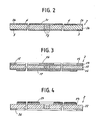
- the molten solder sticks only to the solder-active areas and spreads evenly over the surfaces 2d and 2f to form molten solder layers 4 and 5 of- a uniform thickness as shown in Fig. 2. Since the conductive film lc presents strong affinity to solder, the solder layer 4 wets the entire surface of the film lc by expelling air,which might otherwise be entrapped. Little or no voids thus occur between the adjacent surfaces of the transducer 1 and the nozzle plate 2.
- the nozzle plate 2 is in-pressure transmitting relationship with the liquid in the chamber 3c of the body 3.
- the nozzle plate 2 is deflected in response to the energization of the transducer 1 by an ultrasonic frequency pulse to induce a presssure rise in the liquid to effect ejection of liquid droplets through the nozzle openings 2g.
- a metal disc 12 of a material having solder inactive property such as stainless and titanium is vacuum deposited on opposite surfaces with layers 13 and 14 having a thickness of 1 to 2 micrometers of solder-active material.
- a solder-resist layer 15 of outer, ring pattern and a layer 16 of inner, circular pattern are formed on the layer 13 in a manner identical to that described above.
- a solder-resist layer 17 identical to the layer 2e is also formed on the layer 14.
- Each of the films 13 and 14 preferably comprises a first layer of chromium which assures strong bonding to the solder inactive disc 12 and a second layer deposited on the first.
- the second, overlying layer is composed of gold to prevent oxidation.
- Fig. 4 illustrates a further alternative form of the nozzle plate 2.
- a solder inactive disc 22 is vacuum deposited on one surface with a solder active layer 23 and a solder active layer 24 on the other surface, each of these layers having a pattern complementary to the resist pattern of the corresponding surface in Fig. 3.
- molten solder will form a solder layer 25 of uniform thickness exclusively on the solder-active layer 23 and a solder layer 26 of uniform thickness exclusively on the solder-active layer 24.
Landscapes
- Engineering & Computer Science (AREA)
- Manufacturing & Machinery (AREA)
- Special Spraying Apparatus (AREA)
- Particle Formation And Scattering Control In Inkjet Printers (AREA)
- Pressure-Spray And Ultrasonic-Wave- Spray Burners (AREA)
- Air Humidification (AREA)
- Apparatuses For Generation Of Mechanical Vibrations (AREA)
Applications Claiming Priority (2)
| Application Number | Priority Date | Filing Date | Title |
|---|---|---|---|
| JP57123589A JPS5912775A (ja) | 1982-07-14 | 1982-07-14 | 霧化ポンプユニツト |
| JP123589/82 | 1982-07-14 |
Publications (3)
| Publication Number | Publication Date |
|---|---|
| EP0099730A2 true EP0099730A2 (de) | 1984-02-01 |
| EP0099730A3 EP0099730A3 (en) | 1985-05-22 |
| EP0099730B1 EP0099730B1 (de) | 1987-09-09 |
Family
ID=14864332
Family Applications (1)
| Application Number | Title | Priority Date | Filing Date |
|---|---|---|---|
| EP83304083A Expired EP0099730B1 (de) | 1982-07-14 | 1983-07-13 | Ultraschallzerstäuber und Verfahren zu dessen Herstellung |
Country Status (6)
| Country | Link |
|---|---|
| US (1) | US4530464A (de) |
| EP (1) | EP0099730B1 (de) |
| JP (1) | JPS5912775A (de) |
| AU (1) | AU544478B2 (de) |
| CA (1) | CA1205375A (de) |
| DE (1) | DE3373421D1 (de) |
Cited By (2)
| Publication number | Priority date | Publication date | Assignee | Title |
|---|---|---|---|---|
| EP0262115A3 (en) * | 1986-09-15 | 1989-03-08 | Polaroid Corporation | Drop dispensing device and method for its manufacture |
| WO2015011608A1 (en) * | 2013-07-22 | 2015-01-29 | Koninklijke Philips N.V. | A mesh for use in a nebuliser, and a method of manufacturing the same |
Families Citing this family (63)
| Publication number | Priority date | Publication date | Assignee | Title |
|---|---|---|---|---|
| US4911866A (en) * | 1988-11-25 | 1990-03-27 | The Walt Disney Company | Fog producing apparatus |
| US5152456A (en) * | 1989-12-12 | 1992-10-06 | Bespak, Plc | Dispensing apparatus having a perforate outlet member and a vibrating device |
| US5442384A (en) * | 1990-08-16 | 1995-08-15 | Hewlett-Packard Company | Integrated nozzle member and tab circuit for inkjet printhead |
| US6540154B1 (en) | 1991-04-24 | 2003-04-01 | Aerogen, Inc. | Systems and methods for controlling fluid feed to an aerosol generator |
| US5938117A (en) | 1991-04-24 | 1999-08-17 | Aerogen, Inc. | Methods and apparatus for dispensing liquids as an atomized spray |
| US7628339B2 (en) | 1991-04-24 | 2009-12-08 | Novartis Pharma Ag | Systems and methods for controlling fluid feed to an aerosol generator |
| US6629646B1 (en) * | 1991-04-24 | 2003-10-07 | Aerogen, Inc. | Droplet ejector with oscillating tapered aperture |
| CA2084554C (en) * | 1992-04-02 | 2003-02-11 | Christopher A. Schantz | Integrated nozzle member and tab circuit for inkjet printhead |
| US5450113A (en) * | 1992-04-02 | 1995-09-12 | Hewlett-Packard Company | Inkjet printhead with improved seal arrangement |
| JP3212382B2 (ja) * | 1992-10-01 | 2001-09-25 | 日本碍子株式会社 | 精密ろう付け方法 |
| US6014970A (en) * | 1998-06-11 | 2000-01-18 | Aerogen, Inc. | Methods and apparatus for storing chemical compounds in a portable inhaler |
| US5758637A (en) | 1995-08-31 | 1998-06-02 | Aerogen, Inc. | Liquid dispensing apparatus and methods |
| US6205999B1 (en) | 1995-04-05 | 2001-03-27 | Aerogen, Inc. | Methods and apparatus for storing chemical compounds in a portable inhaler |
| US6085740A (en) | 1996-02-21 | 2000-07-11 | Aerogen, Inc. | Liquid dispensing apparatus and methods |
| US5894980A (en) * | 1995-09-25 | 1999-04-20 | Rapid Analysis Development Comapny | Jet soldering system and method |
| US6276589B1 (en) * | 1995-09-25 | 2001-08-21 | Speedline Technologies, Inc. | Jet soldering system and method |
| US5894985A (en) * | 1995-09-25 | 1999-04-20 | Rapid Analysis Development Company | Jet soldering system and method |
| US5938102A (en) * | 1995-09-25 | 1999-08-17 | Muntz; Eric Phillip | High speed jet soldering system |
| US6186192B1 (en) | 1995-09-25 | 2001-02-13 | Rapid Analysis And Development Company | Jet soldering system and method |
| US5868305A (en) * | 1995-09-25 | 1999-02-09 | Mpm Corporation | Jet soldering system and method |
| DE1005917T1 (de) * | 1998-12-01 | 2001-01-11 | Microflow Engineering S.A., Neuenburg/Neuchatel | Inhalator mit Ultraschallzerstäuber dessen Sprühöffnungen den Maximalamplituden eines stehenden Wellenmusters überlagert sind |
| EP1005916A1 (de) * | 1998-12-01 | 2000-06-07 | Microflow Engineering SA | Inhalator mit Ultraschallzerstäuber dessen Düsenöffnungen den Amplitudenmaxima eines stehenden Wellenmusters überlagert sind |
| US6382522B2 (en) * | 1999-03-08 | 2002-05-07 | S. C. Johnson & Son, Inc. | Attachment method for piezoelectric elements |
| US6235177B1 (en) | 1999-09-09 | 2001-05-22 | Aerogen, Inc. | Method for the construction of an aperture plate for dispensing liquid droplets |
| US7100600B2 (en) | 2001-03-20 | 2006-09-05 | Aerogen, Inc. | Fluid filled ampoules and methods for their use in aerosolizers |
| US7971588B2 (en) | 2000-05-05 | 2011-07-05 | Novartis Ag | Methods and systems for operating an aerosol generator |
| US6948491B2 (en) | 2001-03-20 | 2005-09-27 | Aerogen, Inc. | Convertible fluid feed system with comformable reservoir and methods |
| US7600511B2 (en) | 2001-11-01 | 2009-10-13 | Novartis Pharma Ag | Apparatus and methods for delivery of medicament to a respiratory system |
| US8336545B2 (en) | 2000-05-05 | 2012-12-25 | Novartis Pharma Ag | Methods and systems for operating an aerosol generator |
| MXPA02010884A (es) | 2000-05-05 | 2003-03-27 | Aerogen Ireland Ltd | Aparato y metodo para el suministro de medicamentos al sistema respiratorio. |
| US6543443B1 (en) | 2000-07-12 | 2003-04-08 | Aerogen, Inc. | Methods and devices for nebulizing fluids |
| US6546927B2 (en) | 2001-03-13 | 2003-04-15 | Aerogen, Inc. | Methods and apparatus for controlling piezoelectric vibration |
| US6550472B2 (en) | 2001-03-16 | 2003-04-22 | Aerogen, Inc. | Devices and methods for nebulizing fluids using flow directors |
| US6554201B2 (en) | 2001-05-02 | 2003-04-29 | Aerogen, Inc. | Insert molded aerosol generator and methods |
| US6732944B2 (en) | 2001-05-02 | 2004-05-11 | Aerogen, Inc. | Base isolated nebulizing device and methods |
| US6550691B2 (en) | 2001-05-22 | 2003-04-22 | Steve Pence | Reagent dispenser head |
| US7677467B2 (en) | 2002-01-07 | 2010-03-16 | Novartis Pharma Ag | Methods and devices for aerosolizing medicament |
| MXPA04006629A (es) | 2002-01-07 | 2004-11-10 | Aerogen Inc | Aparatos y metodos para nebulizar fluidos para inhalacion. |
| ES2603067T3 (es) | 2002-01-15 | 2017-02-23 | Novartis Ag | Métodos y sistemas para hacer funcionar un generador de aerosol |
| US6802460B2 (en) * | 2002-03-05 | 2004-10-12 | Microflow Engineering Sa | Method and system for ambient air scenting and disinfecting based on flexible, autonomous liquid atomizer cartridges and an intelligent networking thereof |
| US7387265B2 (en) * | 2002-03-05 | 2008-06-17 | Microwflow Engineering Sa | Method and system for ambient air scenting and disinfecting based on flexible, autonomous liquid atomizer cartridges and an intelligent networking thereof |
| AU2003256253A1 (en) | 2002-05-20 | 2003-12-02 | Aerogen, Inc. | Aerosol for medical treatment and methods |
| EP1386672B1 (de) * | 2002-08-02 | 2010-04-07 | PARI Pharma GmbH | Vorrichtung zur Erzeugung von Flüssigkeitströpfchen |
| US8616195B2 (en) | 2003-07-18 | 2013-12-31 | Novartis Ag | Nebuliser for the production of aerosolized medication |
| US7946291B2 (en) | 2004-04-20 | 2011-05-24 | Novartis Ag | Ventilation systems and methods employing aerosol generators |
| US7290541B2 (en) | 2004-04-20 | 2007-11-06 | Aerogen, Inc. | Aerosol delivery apparatus and method for pressure-assisted breathing systems |
| US7267121B2 (en) | 2004-04-20 | 2007-09-11 | Aerogen, Inc. | Aerosol delivery apparatus and method for pressure-assisted breathing systems |
| US20050240162A1 (en) * | 2004-04-21 | 2005-10-27 | Wen-Pin Chen | Eye treatment device |
| US7249826B2 (en) * | 2004-09-23 | 2007-07-31 | Fujifilm Dimatix, Inc. | Soldering a flexible circuit |
| TWI262824B (en) * | 2005-04-01 | 2006-10-01 | Ind Tech Res Inst | Device for creating fine mist |
| US7954730B2 (en) * | 2005-05-02 | 2011-06-07 | Hong Kong Piezo Co. Ltd. | Piezoelectric fluid atomizer apparatuses and methods |
| ES2514470T3 (es) | 2005-05-25 | 2014-10-28 | Aerogen, Inc. | Sistemas y métodos de vibración |
| US20060289673A1 (en) * | 2005-06-22 | 2006-12-28 | Yu-Ran Wang | Micro-droplet generator |
| TWI331055B (en) * | 2006-09-25 | 2010-10-01 | Ind Tech Res Inst | Atomizing device |
| US7607589B2 (en) * | 2006-11-15 | 2009-10-27 | Health & Life Co., Ltd. | Droplet generation apparatus |
| WO2009155245A1 (en) * | 2008-06-17 | 2009-12-23 | Davicon Corporation | Liquid dispensing apparatus using a passive liquid metering method |
| US20100001090A1 (en) * | 2008-07-03 | 2010-01-07 | Arthur Hampton Neergaard | Liquid Particle Emitting Device |
| WO2010089822A1 (ja) * | 2009-02-09 | 2010-08-12 | 株式会社村田製作所 | 霧化部材及びそれを備える霧化器 |
| US9441542B2 (en) * | 2011-09-20 | 2016-09-13 | General Electric Company | Ultrasonic water atomization system for gas turbine inlet cooling and wet compression |
| CN102896062A (zh) * | 2012-10-26 | 2013-01-30 | 南京航空航天大学 | 一种雾化装置 |
| CN107752129B (zh) * | 2016-08-19 | 2024-04-23 | 湖南中烟工业有限责任公司 | 一种超声雾化片及其制作方法、超声雾化器、电子烟 |
| AR108529A1 (es) * | 2017-05-19 | 2018-08-29 | Juan Carlos Marie Arlandis | Unidad de bombeo de gas para pozos petrolíferos |
| JP7180749B2 (ja) * | 2019-03-20 | 2022-11-30 | 株式会社村田製作所 | 気泡発生装置 |
Family Cites Families (12)
| Publication number | Priority date | Publication date | Assignee | Title |
|---|---|---|---|---|
| US1931311A (en) * | 1932-11-14 | 1933-10-17 | Young Radiator Co | Bonding restricted joint |
| US2836738A (en) * | 1956-05-02 | 1958-05-27 | Joseph W Crownover | Prestressed piezo crystal |
| US3683212A (en) * | 1970-09-09 | 1972-08-08 | Clevite Corp | Pulsed droplet ejecting system |
| SE349676B (de) * | 1971-01-11 | 1972-10-02 | N Stemme | |
| US3738574A (en) * | 1971-06-15 | 1973-06-12 | Siemens Ag | Apparatus for atomizing fluids with a piezoelectrically stimulated oscillator system |
| BE790064A (fr) * | 1971-10-14 | 1973-02-01 | Mead Corp | Generateur de gouttes pour dispositif d'enregistrement. |
| US3900162A (en) * | 1974-01-10 | 1975-08-19 | Ibm | Method and apparatus for generation of multiple uniform fluid filaments |
| US4047186A (en) * | 1976-01-26 | 1977-09-06 | International Business Machines Corporation | Pre-aimed nozzle for ink jet recorder and method of manufacture |
| EP0003363B1 (de) * | 1978-02-01 | 1982-12-01 | E.I. Du Pont De Nemours And Company | Herstellung gedruckter Schaltungen durch Löten von Metallpulver tragenden Abbildungen |
| CA1178191A (en) * | 1980-10-06 | 1984-11-20 | Naoyoshi Maehara | Electric liquid atomizing apparatus |
| AU553251B2 (en) * | 1981-10-15 | 1986-07-10 | Matsushita Electric Industrial Co., Ltd. | Arrangement for ejecting liquid |
| US4605167A (en) * | 1982-01-18 | 1986-08-12 | Matsushita Electric Industrial Company, Limited | Ultrasonic liquid ejecting apparatus |
-
1982
- 1982-07-14 JP JP57123589A patent/JPS5912775A/ja active Granted
-
1983
- 1983-07-11 US US06/512,690 patent/US4530464A/en not_active Expired - Lifetime
- 1983-07-13 DE DE8383304083T patent/DE3373421D1/de not_active Expired
- 1983-07-13 EP EP83304083A patent/EP0099730B1/de not_active Expired
- 1983-07-13 CA CA000432345A patent/CA1205375A/en not_active Expired
- 1983-07-14 AU AU16845/83A patent/AU544478B2/en not_active Ceased
Cited By (4)
| Publication number | Priority date | Publication date | Assignee | Title |
|---|---|---|---|---|
| EP0262115A3 (en) * | 1986-09-15 | 1989-03-08 | Polaroid Corporation | Drop dispensing device and method for its manufacture |
| WO2015011608A1 (en) * | 2013-07-22 | 2015-01-29 | Koninklijke Philips N.V. | A mesh for use in a nebuliser, and a method of manufacturing the same |
| RU2669082C2 (ru) * | 2013-07-22 | 2018-10-08 | Конинклейке Филипс Н.В. | Сетка для использования в небулайзере, а также способ ее изготовления |
| US11357931B2 (en) | 2013-07-22 | 2022-06-14 | Koninklijke Philips N.V. | Mesh for use in a nebuliser, and a method of manufacturing the same |
Also Published As
| Publication number | Publication date |
|---|---|
| JPS6340592B2 (de) | 1988-08-11 |
| DE3373421D1 (en) | 1987-10-15 |
| CA1205375A (en) | 1986-06-03 |
| EP0099730A3 (en) | 1985-05-22 |
| AU1684583A (en) | 1984-01-19 |
| EP0099730B1 (de) | 1987-09-09 |
| US4530464A (en) | 1985-07-23 |
| AU544478B2 (en) | 1985-05-30 |
| JPS5912775A (ja) | 1984-01-23 |
Similar Documents
| Publication | Publication Date | Title |
|---|---|---|
| US4530464A (en) | Ultrasonic liquid ejecting unit and method for making same | |
| CA1206995A (en) | Arrangement for ejecting liquid | |
| EP3826775B1 (de) | Zerstäuber | |
| CA1206996A (en) | Ultrasonic liquid ejecting apparatus | |
| EP0049636B1 (de) | Elektrischer Flüssigkeitszerstäuber | |
| Maehara et al. | Influence of the vibrating system of a multipinhole‐plate ultrasonic nebulizer on its performance | |
| US4696719A (en) | Monomer atomizer for vaporization | |
| JP3659593B2 (ja) | 液体スプレー装置及び方法 | |
| US3243122A (en) | Ultrasonic spray apparatus | |
| EP0844027A1 (de) | Zerstäubungsvorrichtung und verfahren die akustische oberflächenwellen anwenden | |
| JP2023553583A (ja) | 吸入装置のためのエアロゾル発生器 | |
| KR0165677B1 (ko) | 잉크-제트 방식 인쇄기용 노즐 | |
| JPH0824739A (ja) | 超音波噴霧器 | |
| JP3375652B2 (ja) | 球形単分散粒子の製造方法および装置 | |
| KR102889603B1 (ko) | 음향영동 인쇄를 위한 서브파장 공진기 | |
| JPH1034916A (ja) | 記録素子および記録装置 | |
| JPS6258784B2 (de) | ||
| KR20040084532A (ko) | 액적 발생장치 | |
| JPH03188966A (ja) | 接着剤塗布装置 | |
| CN121848662A (zh) | 雾化喷射部件、装置、及雾化喷射方法 | |
| JPS6068071A (ja) | 霧化ポンプ | |
| JPS58180259A (ja) | 霧化装置 | |
| JPS60172377A (ja) | 霧化ポンプ | |
| JPS6031558B2 (ja) | 霧化装置 | |
| JPS6124193B2 (de) |
Legal Events
| Date | Code | Title | Description |
|---|---|---|---|
| PUAI | Public reference made under article 153(3) epc to a published international application that has entered the european phase |
Free format text: ORIGINAL CODE: 0009012 |
|
| AK | Designated contracting states |
Designated state(s): DE FR GB |
|
| PUAL | Search report despatched |
Free format text: ORIGINAL CODE: 0009013 |
|
| AK | Designated contracting states |
Designated state(s): DE FR GB |
|
| 17P | Request for examination filed |
Effective date: 19850621 |
|
| 17Q | First examination report despatched |
Effective date: 19860221 |
|
| D17Q | First examination report despatched (deleted) | ||
| GRAA | (expected) grant |
Free format text: ORIGINAL CODE: 0009210 |
|
| AK | Designated contracting states |
Kind code of ref document: B1 Designated state(s): DE FR GB |
|
| REF | Corresponds to: |
Ref document number: 3373421 Country of ref document: DE Date of ref document: 19871015 |
|
| ET | Fr: translation filed | ||
| PLBE | No opposition filed within time limit |
Free format text: ORIGINAL CODE: 0009261 |
|
| STAA | Information on the status of an ep patent application or granted ep patent |
Free format text: STATUS: NO OPPOSITION FILED WITHIN TIME LIMIT |
|
| 26N | No opposition filed | ||
| REG | Reference to a national code |
Ref country code: GB Ref legal event code: 746 Effective date: 19960628 |
|
| PGFP | Annual fee paid to national office [announced via postgrant information from national office to epo] |
Ref country code: DE Payment date: 20000710 Year of fee payment: 18 |
|
| PGFP | Annual fee paid to national office [announced via postgrant information from national office to epo] |
Ref country code: FR Payment date: 20000711 Year of fee payment: 18 |
|
| PGFP | Annual fee paid to national office [announced via postgrant information from national office to epo] |
Ref country code: GB Payment date: 20000713 Year of fee payment: 18 |
|
| PG25 | Lapsed in a contracting state [announced via postgrant information from national office to epo] |
Ref country code: GB Free format text: LAPSE BECAUSE OF NON-PAYMENT OF DUE FEES Effective date: 20010713 |
|
| GBPC | Gb: european patent ceased through non-payment of renewal fee |
Effective date: 20010713 |
|
| PG25 | Lapsed in a contracting state [announced via postgrant information from national office to epo] |
Ref country code: FR Free format text: LAPSE BECAUSE OF NON-PAYMENT OF DUE FEES Effective date: 20020329 |
|
| PG25 | Lapsed in a contracting state [announced via postgrant information from national office to epo] |
Ref country code: DE Free format text: LAPSE BECAUSE OF NON-PAYMENT OF DUE FEES Effective date: 20020501 |
|
| REG | Reference to a national code |
Ref country code: FR Ref legal event code: ST |