EP0099756A2 - Appareil de diaphanoscopie - Google Patents
Appareil de diaphanoscopie Download PDFInfo
- Publication number
- EP0099756A2 EP0099756A2 EP83304189A EP83304189A EP0099756A2 EP 0099756 A2 EP0099756 A2 EP 0099756A2 EP 83304189 A EP83304189 A EP 83304189A EP 83304189 A EP83304189 A EP 83304189A EP 0099756 A2 EP0099756 A2 EP 0099756A2
- Authority
- EP
- European Patent Office
- Prior art keywords
- light
- diaphanoscopy
- different wavelengths
- sequentially
- detector
- Prior art date
- Legal status (The legal status is an assumption and is not a legal conclusion. Google has not performed a legal analysis and makes no representation as to the accuracy of the status listed.)
- Granted
Links
Images

Classifications
-
- A—HUMAN NECESSITIES
- A61—MEDICAL OR VETERINARY SCIENCE; HYGIENE
- A61B—DIAGNOSIS; SURGERY; IDENTIFICATION
- A61B5/00—Measuring for diagnostic purposes; Identification of persons
- A61B5/0059—Measuring for diagnostic purposes; Identification of persons using light, e.g. diagnosis by transillumination, diascopy, fluorescence
- A61B5/0082—Measuring for diagnostic purposes; Identification of persons using light, e.g. diagnosis by transillumination, diascopy, fluorescence adapted for particular medical purposes
- A61B5/0091—Measuring for diagnostic purposes; Identification of persons using light, e.g. diagnosis by transillumination, diascopy, fluorescence adapted for particular medical purposes for mammography
-
- A—HUMAN NECESSITIES
- A61—MEDICAL OR VETERINARY SCIENCE; HYGIENE
- A61B—DIAGNOSIS; SURGERY; IDENTIFICATION
- A61B5/00—Measuring for diagnostic purposes; Identification of persons
- A61B5/43—Detecting, measuring or recording for evaluating the reproductive systems
- A61B5/4306—Detecting, measuring or recording for evaluating the reproductive systems for evaluating the female reproductive systems, e.g. gynaecological evaluations
- A61B5/4312—Breast evaluation or disorder diagnosis
-
- G—PHYSICS
- G01—MEASURING; TESTING
- G01N—INVESTIGATING OR ANALYSING MATERIALS BY DETERMINING THEIR CHEMICAL OR PHYSICAL PROPERTIES
- G01N21/00—Investigating or analysing materials by the use of optical means, i.e. using sub-millimetre waves, infrared, visible or ultraviolet light
- G01N21/17—Systems in which incident light is modified in accordance with the properties of the material investigated
- G01N21/25—Colour; Spectral properties, i.e. comparison of effect of material on the light at two or more different wavelengths or wavelength bands
- G01N21/31—Investigating relative effect of material at wavelengths characteristic of specific elements or molecules, e.g. atomic absorption spectrometry
- G01N21/314—Investigating relative effect of material at wavelengths characteristic of specific elements or molecules, e.g. atomic absorption spectrometry with comparison of measurements at specific and non-specific wavelengths
Definitions
- the invention relates to diaphanoscopy apparatus for use for example in non-destructive testing or medical diagnostics.
- Transillumination i.e. the passing of light through tissue
- Earlier apparatus and techniques are described in the U.S Patent Specifications 3,127,115; 3,371,202; ,527,932; 3,674,008; 3,711,700; 3,732,416; 3,769,963; 4,077,399; 4,212,306; 4,286,602; USSR Patent Specifications 279,879 and 591,178; in "Diaphanologie mammaire” by C. Gross J. Radiol Electrol 1972 Vol 53 No 4 pp 297-306 and "Etude diphanoscopique des alteration dystrophiques du spur" by C. Maggio Senologia June 1978 pp 69-71.
- the invention provides a diaphanoscopy apparatus which is characterised in that means are provided for sequentially illuminating the object with light of at least two different wavelengths, detector means are provided for sensing transilluminated light in relation to each sequential illumination, recording means are provided for separately recording the output of the detector means related to the sequential illumination, and a display means is provided which represents the absorption characteristics of the object at the different wavelengths.
- the object examined may be human body tissue. Information commensurate with the light which passes through the tissue at each illumination wavelength can be stored. The stored information can be subsequently employed to produce an image which represents the absorption characteristics of the tissue which has been illuminated.
- an encoding means is provided for providing a characteristic value which is a function of the sequential outputs of the detector means relating to the different wavelengths and the detector means is adapted for scanning so as to produce an image from a series of characteristic values for different parts of the object.
- the characteristic value may be a ratio of the successive detector outputs and may be highly revealing of tissue abnormalities.
- the apparatus includes a source of transillumination light at different frequencies or within different pre-selected bands of frequency .
- the term "wavelengths" is used in a general indicative fashion.
- the sequentially emitted light may share some part of the spectrum and may overlap but the spectral characteristics should be sufficiently different to give meaningful results.
- the light source provides light in the red and near infrared regions.
- the tissue under examination is sequentially illuminated by the different frequency light.
- the light which passes through the tissue is sensed by a video camera synchronized with the light source.
- the output of the camera is thus a series of signals corresponding to images of the tissue as illuminated at the light at the different sequentially applied wavelengths. These video signals are separately stored and subsequently employed to form a composite image.
- the information commensurate with the stored images is employed to produce a display wherein each point of the display contains information characteristic of the ratio of the light within each frequency band which has passed through the tissue at a corresponding point.
- a colour may be assigned to each ratio and a multi-colour image formed.
- the invention secondly provides a non-destructive testing method using diaphanoscopy in which an object is transilluminated with light, characterised in that the transilluminating light provides sequentially at least two different spectral compositions, the transilluminated light is detected and the intensity of the sequentially transilluminated light separately recorded for a plurality of object locations and a characteristic value is derived from a combination of the respective intensity values and displayed to provide an image representing the absorption of light on transillumination of the object at different wavelengths.
- light in the red and near infrared spectrum is employed for transilluminating human body tissue.
- Light at the different wavelengths chosen will be absorbed by the tissue as a function of wavelength and tissue type.
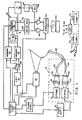
- "White" light is generated by a pair of strobe lights 10 and 12.
- the strobe lights 10 and 12 include flash lamps which generate light in a comparatively broad spectrum including the red and near infrared regions.
- the strobe lights 10 and 12 may include commercially available xenon flash tubes.
- the strobe lights 10 and 12 are respectively controlled by power supplies 14 and 16 which, in response to input commands, apply a trigger pulse to the flash tubes whereby the gas in the tube will ionize and a capacitor will discharge through the tube producing a light pulse of short duration.
- the .duration of the light pulse produced by strobe lights 10 and 12 is ten microseconds and the output power of the lamps is one joule.
- the light produced by strobe lights 10 and 12 is respectively collected by condensing lens systems 18 and 20 which focus the light at the ends of respective fibre optic bundles 22 and 24.
- Filters 26 and 28 are disposed in the light path between respective strobe lights 10 and 12 and the associated fibre optic bundles 22 and 24.
- the filter 26, in the embodiment being described, will pass only wavelengths in the 650 to 750 nanometer, i.e. red, region.
- the filter 28 will pass light only in the 750 to 850 nanometer, i.e. near infrared, region.
- the fibre optic bundles 22 and 24 are combined into a single bundle 30.
- the free end of fibre optic bundle 30 is placed in contact with the skin to produce a source of transilluminating light.
- the strobe lights 10 and 12 are alternately energized in synchronism with a video system whereby the tissue of interest will be transilluminated first with red light and then with light in the near infrared region.
- transillumination video camera 32 is focused on the breast or other object being examined.
- camera 32 will include a silicon face plate tube which is responsive in the region from 650 nanometers to 900 nanometers.
- the camera tube may, for example, comprise a silicon diode array type device available from RCA under the trademark " Ultricon".
- Ultricon The short bursts of light received by the camera 32 have the effect of discharging, in varying degrees, the surface of the video camera tube. Scanning of the tube surface by an electron beam produces, in the conventional manner, a video output signal.
- This analog output signal is delivered as the input to an analog-to-digital converter 34.
- the digitally coded signals from converter 34 are alternately supplied, via a switch 36, to a pair of frame memories 38 to 40.
- the memories 38 and 40 may, for example, comprise dynamic memory elements having eight bits of memory for each picture location i.e. each pixel.
- the controller 42 comprises a clock, down counter and gates and provides the vertical and horizontal synchronizing signals to the camera 32.
- the controller 42 will supply a gating pulse 14' to the power supply 14 which will cause the flash tube of strobe light 10 to fire thereby producing an intense burst of light which lasts a few microseconds.
- this light will be collected by the condensing lens system 18, filtered by filter 26 and the resulting "red" light delivered to the end of fibre optic bundle 30 which is in contact with the patient.
- the logic circuit 42 will also control the operation of switch 36, which will typically be an electronic switch, such that the digitally encoded signal produced during a single frame of scanning of the tube in camera 32 will be loaded into memory 38.
- the memory 38 will thus contain information commensurate with the red light which has passed through the tissue under examination.
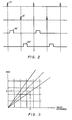
- the time during which the data is being entered into memory 38 i.e. one frame time, is indicated on Figure 2 at 38'. During the next frame the vidicon is permited to recharge fully.
- the controller logic 42 will produce an output signal, indicated at 16' in Figure 2, which causes the firing of the flash tube in the strobe light 12. Accordingly, the breast will, during this retrace time, be illuminated with light in the near infrared region, this light being produced from the output of the strobe light 12 by the filter 28 and delivered to the branch 24 of the bifurcated fibre optic bundle.
- the control logic 42 will operate the switch 36 so as to deliver the digitally encoded information commensurate with the near infrared light transmitted through the tissue into the frame memory 40.
- the information in the memories 38 and 40 is simultaneously read by an encoder which is indicated generally at 44.
- the encoder 44 will comprise a RAM which functions as a look-up table.
- the encoder 44 has been functionally depicted as a divider 46 and a memory 48.
- the memory 48 will have, for example, 2 8 x 2 8 addresses and numbers corresponding to the intensity of two colours, typically red and green, commensurate with ratios of the numbers which may be stored at each pixel in memories 38 and 40 will be stored at the memory locations in memory 48.
- the data stored in the memories 38 and 40 will be read by the memory 48 twice the rate of loading of memories 38 and 40.
- the number stored at the corresponding memory locations in memories 38 and 40 are employed to address memory 48.
- the memory 48 will produce a pair of colour related, digitally coded output signals for each pizel. This is functionally equivalent to dividing the numbers stored at the memory locations in memories 38 and 40 in the divider 46 and employing the thus produced ratio to address the memory 48.
- the numbers which are read out of memory 48 comprise digitally coded chrominance signals which, in the example being described, will correspond to a red "R" intensity and a green "G" intensity.
- the numbers read from the memories 38 and 40 are also applied to an adder 50 where they are summed.
- the output of adder 50 is delivered to a divide by two circuit 52.
- the output of divider 52 is a digitally encoded average luminance of "Y" signal.
- the "R” and “G” chrominance signals from the memory 48 are converted to analog form by means of digital-to- analog converters 54 and 56 while the average luminance signal is converted to analog form by a digital- to- analog converter 58.
- the outputs of the converters 54 and 56 are respectively applied as first inputs to differential amplifiers 60 and 62.
- the second input to amplifiers 60 and 62 is the luminance signal from the converter 58.
- the combined luminance and chrominance signals appearing at the outputs or amplifiers 60 and 62 are applied to a standard TV modulater 64 which also receives synchronizing signals from the controller 42.
- the modulator 64 provides a composite colour video signal which is delivered to a TV monitor 66. This composite signal will, in the customary fashion, provide horizontal sync, colour burst and colour modulation information for each frame.
- the encoder 44 may look at the most significant six bits of the signals stored in memories 38 and 40 while the adder 50 looked at all eight bits of the stored data.
- the invention may be employed as an analytical tool wherein the ratio of the absorption by the object under examination of light at the transillumination frequencies at any point of interest may be read out and displayed on a monitor 66.
- a joy stick 68 coupled to potentiometers indicated schematically at 70 and 72, may be employed to provide input signals to an analog-to-digital converter 74.
- the converter 74 will, in turn, provide address information to the memories 38 and 40.
- a spot or cursor will be displayed on monitor 66 and the contents of the memories will be delivered to a microprocessor via buffers.
- the microprocessor will, pursuant to its instructions, cause an alphanumeric display which may, for example, be the ratio of absorption of the two transilluminating light wavelengths.
- Figure 3 may be considered a graphical representation of the function of the encoder 44.
- the ratio of the numbers commensurate with the amount of light at the top transillumination wave lengths which is passed through the tissue under examination defines straight line curves. Each discrete curve will have assigned thereto chrominance values corresponding to red and green signal amplitude.
- the "normalizing” may be accomplished by varying the voltages applied to flash tubes 10 and 12 ( Figure 1) to thereby vary the intensity of the two colours of light. It is also possible to separate the light passing through the tissue into two beams which are subsequently filtered and detected, the adjustment being made to the resulting signals. A further possibility would be to employ two vidicons and selectively vary the gain thereof to achieve the "normalization".
- the above-discussed step of "normalizing” is achieved through use of the apparatus of Figures 4 and 5 in place of the pair of flash lamps 10 and 12 and their associated power supplies, lenses and filters as shown in Figure 1.
- a motor 80 rotates a drive shaft 82 at a speed determined by a controller 84, controller 84 being responsive to output pulses received from the control logic 42.
- a disc 86 is mounted on shaft 82 for rotation therewith.
- Disc 86 is provided with a pair of equal size and oppositely disposed windows. Filters, which correspond respectively to filters 26 and 28 of the Figure 1 embodiment, are respectively mounted in the windows in disc 86 as indicated at 26' and 28'.
- a source of white light is positioned such that the light emitted therefrom will alternately pass through filters 26' and 28' as the disc 86 rotates.
- the end of the fibre optic bundle 30 is located in alignment with light source 88.
- the speed of motor 80 will be selected such that the tissue under examination will alternately be transilluminated with the different colour light in synchronism with the operation of the camera 32, i.e.
- the tissue during a first frame the tissue will be illuminated with red, during a second frame the vidicon will be read out, during the third frame the vidicon screen will be recharged, during the fourth frame the tissue will be illuminated with infrared, during the fifth frame the infrared data will be read out of the vidicon, during the sixth frame the vidicon screen will be recharged, and the process will thereafter repeat.
- the "normalization" procedure will typically be performed so as to cause all normal tissue to appear in white on a black background.
- the apparatus will be adjusted so that transillumination of the patient's normal tissue will result in camera 32 receiving light of equal intensity during the illumination of the tissue with both red and infrared.
- This normalization. is achieved by mounting a shutter 90 for rotation with the disc 86.
- Shutter 90 is provided with a pair of different size windows 92 and 93, window 93 being substantially equal in size and shape to the filters 26' and 28'.
- a differential indicated generally at 94
- the shutter 90 is manually rotatable relative to the disc 86 so that one of the filters 26' and 28' may be partially covered while the other remains fully uncovered.
- This relative rotation is achieved via a control input 94 which can be employed to either advance or retard the shutter 90 relative to the disc 86 while the two discs are rotating at the same speed.
- a speed reduction mechanism 98 in the form of pulleys and belts, is interposed between the differential 94 and the shutter 90 for the purpose of causing the shutter to rotate at the same speed as the filter carrying disc.
- the invention has been described as alternately illuminating the object under examination with light of two different wavelengths, the invention is not limited to transillumination with light of only two different colours or to the use of light within the frequency ranges discussed.
Landscapes
- Health & Medical Sciences (AREA)
- Life Sciences & Earth Sciences (AREA)
- Physics & Mathematics (AREA)
- Spectroscopy & Molecular Physics (AREA)
- Pathology (AREA)
- General Health & Medical Sciences (AREA)
- Biomedical Technology (AREA)
- Biophysics (AREA)
- Medical Informatics (AREA)
- Molecular Biology (AREA)
- Surgery (AREA)
- Animal Behavior & Ethology (AREA)
- Engineering & Computer Science (AREA)
- Public Health (AREA)
- Veterinary Medicine (AREA)
- Heart & Thoracic Surgery (AREA)
- Chemical & Material Sciences (AREA)
- Analytical Chemistry (AREA)
- Biochemistry (AREA)
- General Physics & Mathematics (AREA)
- Immunology (AREA)
- Gynecology & Obstetrics (AREA)
- Reproductive Health (AREA)
- Investigating Or Analysing Materials By Optical Means (AREA)
- Measuring And Recording Apparatus For Diagnosis (AREA)
- Ultra Sonic Daignosis Equipment (AREA)
Applications Claiming Priority (2)
| Application Number | Priority Date | Filing Date | Title |
|---|---|---|---|
| US39986582A | 1982-07-19 | 1982-07-19 | |
| US399865 | 1982-07-19 |
Publications (3)
| Publication Number | Publication Date |
|---|---|
| EP0099756A2 true EP0099756A2 (fr) | 1984-02-01 |
| EP0099756A3 EP0099756A3 (en) | 1985-01-30 |
| EP0099756B1 EP0099756B1 (fr) | 1988-06-01 |
Family
ID=23581278
Family Applications (1)
| Application Number | Title | Priority Date | Filing Date |
|---|---|---|---|
| EP19830304189 Expired EP0099756B1 (fr) | 1982-07-19 | 1983-07-19 | Appareil de diaphanoscopie |
Country Status (5)
| Country | Link |
|---|---|
| EP (1) | EP0099756B1 (fr) |
| JP (1) | JPS5932852A (fr) |
| AU (1) | AU1687983A (fr) |
| CA (1) | CA1204605A (fr) |
| DE (1) | DE3376794D1 (fr) |
Cited By (13)
| Publication number | Priority date | Publication date | Assignee | Title |
|---|---|---|---|---|
| GB2162709A (en) * | 1984-06-22 | 1986-02-05 | Hitachi Ltd | A magnetic bubble memory |
| GB2162939A (en) * | 1984-08-07 | 1986-02-12 | Sclavo Spa | A multiple wavelength light photometer for non-invasive monitoring |
| EP0359433A1 (fr) * | 1988-08-26 | 1990-03-21 | Polartechnics Ltd | Sonde physiologique |
| EP0385608A1 (fr) * | 1989-02-15 | 1990-09-05 | Hitachi, Ltd. | Procédé pour examiner optiquement le corps humain et appareil pour celui-ci |
| AU614660B2 (en) * | 1988-08-26 | 1991-09-05 | Polartechnics Limited | Physiological probe |
| WO1993011704A1 (fr) * | 1991-12-17 | 1993-06-24 | Eduard Emmanuilovich Godik | Procede et dispositif pour le diagnostic d'un organisme vivant |
| EP0647120A4 (fr) * | 1992-06-17 | 1997-09-10 | Nim Inc | Procedes d'examen de sujets utilisant la migration de photons et des techniques de directivite. |
| US5820558A (en) * | 1994-12-02 | 1998-10-13 | Non-Invasive Technology, Inc. | Optical techniques for examination of biological tissue |
| US5865743A (en) * | 1994-02-23 | 1999-02-02 | Dynamics Imaging, Inc. | Method of living organism multimodal functional mapping |
| US6002958A (en) * | 1992-12-24 | 1999-12-14 | Dynamics Imaging, Inc. | Method and apparatus for diagnostics of internal organs |
| US6058324A (en) * | 1993-06-17 | 2000-05-02 | Non-Invasive Technology, Inc. | Examination and imaging of biological tissue |
| US6192262B1 (en) | 1994-02-23 | 2001-02-20 | Dobi Medical Systems, Llc | Method of living organism multimodal functional mapping |
| US6542772B1 (en) | 1994-12-02 | 2003-04-01 | Non-Invasive Technology, Inc. | Examination and imaging of biological tissue |
Families Citing this family (6)
| Publication number | Priority date | Publication date | Assignee | Title |
|---|---|---|---|---|
| JPH01132036U (fr) * | 1988-03-01 | 1989-09-07 | ||
| DE69934482T2 (de) | 1998-02-11 | 2007-09-27 | Non-Invasive Technology, Inc. | Nachweis, abbildung und kennzeichnung von brustumoren |
| WO1999040841A1 (fr) | 1998-02-11 | 1999-08-19 | Non-Invasive Technology, Inc. | Visualisation et caracterisation du tissu cerebral |
| WO2008010604A1 (fr) * | 2006-07-19 | 2008-01-24 | School Juridical Person Kitasato Gakuen | Dispositif d'imagerie des vaisseaux sanguins et système pour analyser une distribution des vaisseaux sanguins |
| US8000777B2 (en) * | 2006-09-19 | 2011-08-16 | Kci Licensing, Inc. | System and method for tracking healing progress of tissue |
| JP6361193B2 (ja) * | 2014-03-14 | 2018-07-25 | 富士通株式会社 | 光源装置、発光方法及び端末装置 |
Family Cites Families (5)
| Publication number | Priority date | Publication date | Assignee | Title |
|---|---|---|---|---|
| GB1490070A (en) * | 1974-01-31 | 1977-10-26 | Metals Res Ltd | Electrical circuit and apparatus and method of operating same for making measurements on differently coloured features |
| GB1574823A (en) * | 1976-03-27 | 1980-09-10 | Emi Ltd | Video display arrangements |
| JPS54148586A (en) * | 1978-05-15 | 1979-11-20 | Minolta Camera Co Ltd | Jaundice meter |
| US4223995A (en) * | 1978-08-22 | 1980-09-23 | Fletcher Taylor C | Calibration system for spectrophotometers |
| GB2068537B (en) * | 1980-02-04 | 1984-11-14 | Energy Conversion Devices Inc | Examining biological materials |
-
1983
- 1983-07-15 AU AU16879/83A patent/AU1687983A/en not_active Abandoned
- 1983-07-15 CA CA000432515A patent/CA1204605A/fr not_active Expired
- 1983-07-19 DE DE8383304189T patent/DE3376794D1/de not_active Expired
- 1983-07-19 JP JP13264183A patent/JPS5932852A/ja active Pending
- 1983-07-19 EP EP19830304189 patent/EP0099756B1/fr not_active Expired
Cited By (18)
| Publication number | Priority date | Publication date | Assignee | Title |
|---|---|---|---|---|
| GB2162709A (en) * | 1984-06-22 | 1986-02-05 | Hitachi Ltd | A magnetic bubble memory |
| GB2162939A (en) * | 1984-08-07 | 1986-02-12 | Sclavo Spa | A multiple wavelength light photometer for non-invasive monitoring |
| EP0359433A1 (fr) * | 1988-08-26 | 1990-03-21 | Polartechnics Ltd | Sonde physiologique |
| US5036853A (en) * | 1988-08-26 | 1991-08-06 | Polartechnics Ltd. | Physiological probe |
| AU614660B2 (en) * | 1988-08-26 | 1991-09-05 | Polartechnics Limited | Physiological probe |
| EP0385608A1 (fr) * | 1989-02-15 | 1990-09-05 | Hitachi, Ltd. | Procédé pour examiner optiquement le corps humain et appareil pour celui-ci |
| US5148022A (en) * | 1989-02-15 | 1992-09-15 | Hitachi, Ltd. | Method for optically inspecting human body and apparatus for the same |
| WO1993011704A1 (fr) * | 1991-12-17 | 1993-06-24 | Eduard Emmanuilovich Godik | Procede et dispositif pour le diagnostic d'un organisme vivant |
| EP0647120A4 (fr) * | 1992-06-17 | 1997-09-10 | Nim Inc | Procedes d'examen de sujets utilisant la migration de photons et des techniques de directivite. |
| US6272367B1 (en) | 1992-06-17 | 2001-08-07 | Non-Invasive Technology, Inc. | Examination of a biological tissue using photon migration between a plurality of input and detection locations |
| US7010341B2 (en) | 1992-06-17 | 2006-03-07 | Noninvasive Technology, Inc. | Examination of subjects using photon migration with high directionality techniques |
| US6002958A (en) * | 1992-12-24 | 1999-12-14 | Dynamics Imaging, Inc. | Method and apparatus for diagnostics of internal organs |
| US6058324A (en) * | 1993-06-17 | 2000-05-02 | Non-Invasive Technology, Inc. | Examination and imaging of biological tissue |
| US5865743A (en) * | 1994-02-23 | 1999-02-02 | Dynamics Imaging, Inc. | Method of living organism multimodal functional mapping |
| US6192262B1 (en) | 1994-02-23 | 2001-02-20 | Dobi Medical Systems, Llc | Method of living organism multimodal functional mapping |
| US5820558A (en) * | 1994-12-02 | 1998-10-13 | Non-Invasive Technology, Inc. | Optical techniques for examination of biological tissue |
| US6542772B1 (en) | 1994-12-02 | 2003-04-01 | Non-Invasive Technology, Inc. | Examination and imaging of biological tissue |
| US7139603B2 (en) | 1994-12-02 | 2006-11-21 | Non-Invasive Technology Inc | Optical techniques for examination of biological tissue |
Also Published As
| Publication number | Publication date |
|---|---|
| JPS5932852A (ja) | 1984-02-22 |
| AU1687983A (en) | 1984-01-26 |
| EP0099756A3 (en) | 1985-01-30 |
| EP0099756B1 (fr) | 1988-06-01 |
| CA1204605A (fr) | 1986-05-20 |
| DE3376794D1 (de) | 1988-07-07 |
Similar Documents
| Publication | Publication Date | Title |
|---|---|---|
| EP0099756A2 (fr) | Appareil de diaphanoscopie | |
| US4495949A (en) | Transillumination method | |
| US4467812A (en) | Transillumination apparatus | |
| US4651743A (en) | Diaphanoscopy method | |
| US4604992A (en) | Endoscope system | |
| DE4136034C2 (fr) | ||
| DE19535114B4 (de) | Endoskopsystem mit Fluoreszenzdiagnose | |
| US4261344A (en) | Color endoscope | |
| US4740837A (en) | Endoscope apparatus with solid state image pickup device | |
| DE3246239C2 (fr) | ||
| US4253447A (en) | Color endoscope with charge coupled device and television viewing | |
| US4535758A (en) | Signal level control for video system | |
| US4593313A (en) | Endoscope | |
| USRE31289E (en) | Color endoscope with charge coupled device and television viewing | |
| US4914512A (en) | Electronic endoscope apparatus capable of displaying hemoglobin concentration on color image | |
| DE19919943B4 (de) | Videovorrichtung für ein Endoskop zur Fluoreszenzdiagnostik | |
| US3748471A (en) | False color radiant energy detection method and apparatus | |
| DE102006042670B4 (de) | Elektronisches Endoskopsystem | |
| US5078150A (en) | Spectral diagnosing apparatus with endoscope | |
| DE3718603C2 (de) | Farbbild-abtastvorrichtung, sowie elektronisches endoskop hiermit | |
| DE69527571T2 (de) | Sichtgerät mit Bildverstärkung | |
| US4616657A (en) | Diaphanoscopy apparatus | |
| DE10031530A1 (de) | Endoskopsystem und Beleuchtungsvorrichtung hierfür | |
| JP2001518241A (ja) | 可視光エネルギーと赤外線光エネルギーを別個に処理する画像システム | |
| EP0244111B1 (fr) | Système de formation d'image |
Legal Events
| Date | Code | Title | Description |
|---|---|---|---|
| PUAI | Public reference made under article 153(3) epc to a published international application that has entered the european phase |
Free format text: ORIGINAL CODE: 0009012 |
|
| AK | Designated contracting states |
Designated state(s): CH DE FR GB IT LI NL SE |
|
| PUAL | Search report despatched |
Free format text: ORIGINAL CODE: 0009013 |
|
| AK | Designated contracting states |
Designated state(s): CH DE FR GB IT LI NL SE |
|
| 17P | Request for examination filed |
Effective date: 19850715 |
|
| 17Q | First examination report despatched |
Effective date: 19860903 |
|
| D17Q | First examination report despatched (deleted) | ||
| GRAA | (expected) grant |
Free format text: ORIGINAL CODE: 0009210 |
|
| AK | Designated contracting states |
Kind code of ref document: B1 Designated state(s): CH DE FR GB IT LI NL SE |
|
| PG25 | Lapsed in a contracting state [announced via postgrant information from national office to epo] |
Ref country code: NL Effective date: 19880601 Ref country code: LI Effective date: 19880601 Ref country code: IT Free format text: LAPSE BECAUSE OF FAILURE TO SUBMIT A TRANSLATION OF THE DESCRIPTION OR TO PAY THE FEE WITHIN THE PRESCRIBED TIME-LIMIT;WARNING: LAPSES OF ITALIAN PATENTS WITH EFFECTIVE DATE BEFORE 2007 MAY HAVE OCCURRED AT ANY TIME BEFORE 2007. THE CORRECT EFFECTIVE DATE MAY BE DIFFERENT FROM THE ONE RECORDED. Effective date: 19880601 Ref country code: FR Free format text: THE PATENT HAS BEEN ANNULLED BY A DECISION OF A NATIONAL AUTHORITY Effective date: 19880601 Ref country code: CH Effective date: 19880601 |
|
| PG25 | Lapsed in a contracting state [announced via postgrant information from national office to epo] |
Ref country code: SE Effective date: 19880630 |
|
| REF | Corresponds to: |
Ref document number: 3376794 Country of ref document: DE Date of ref document: 19880707 |
|
| REG | Reference to a national code |
Ref country code: CH Ref legal event code: PL |
|
| EN | Fr: translation not filed | ||
| NLV1 | Nl: lapsed or annulled due to failure to fulfill the requirements of art. 29p and 29m of the patents act | ||
| PLBE | No opposition filed within time limit |
Free format text: ORIGINAL CODE: 0009261 |
|
| 26N | No opposition filed | ||
| PGFP | Annual fee paid to national office [announced via postgrant information from national office to epo] |
Ref country code: DE Payment date: 19890724 Year of fee payment: 7 |
|
| PGFP | Annual fee paid to national office [announced via postgrant information from national office to epo] |
Ref country code: GB Payment date: 19890731 Year of fee payment: 7 |
|
| PG25 | Lapsed in a contracting state [announced via postgrant information from national office to epo] |
Ref country code: GB Effective date: 19900719 |
|
| GBPC | Gb: european patent ceased through non-payment of renewal fee | ||
| PG25 | Lapsed in a contracting state [announced via postgrant information from national office to epo] |
Ref country code: DE Effective date: 19910403 |