EP0100039A2 - Soufflerie d'air de refroidissement pour moteur à combustion interne - Google Patents
Soufflerie d'air de refroidissement pour moteur à combustion interne Download PDFInfo
- Publication number
- EP0100039A2 EP0100039A2 EP83106981A EP83106981A EP0100039A2 EP 0100039 A2 EP0100039 A2 EP 0100039A2 EP 83106981 A EP83106981 A EP 83106981A EP 83106981 A EP83106981 A EP 83106981A EP 0100039 A2 EP0100039 A2 EP 0100039A2
- Authority
- EP
- European Patent Office
- Prior art keywords
- internal combustion
- combustion engine
- cooling fan
- housing
- receiving
- Prior art date
- Legal status (The legal status is an assumption and is not a legal conclusion. Google has not performed a legal analysis and makes no representation as to the accuracy of the status listed.)
- Granted
Links
Images


Classifications
-
- F—MECHANICAL ENGINEERING; LIGHTING; HEATING; WEAPONS; BLASTING
- F01—MACHINES OR ENGINES IN GENERAL; ENGINE PLANTS IN GENERAL; STEAM ENGINES
- F01P—COOLING OF MACHINES OR ENGINES IN GENERAL; COOLING OF INTERNAL-COMBUSTION ENGINES
- F01P5/00—Pumping cooling-air or liquid coolants
- F01P5/02—Pumping cooling-air; Arrangements of cooling-air pumps, e.g. fans or blowers
-
- F—MECHANICAL ENGINEERING; LIGHTING; HEATING; WEAPONS; BLASTING
- F01—MACHINES OR ENGINES IN GENERAL; ENGINE PLANTS IN GENERAL; STEAM ENGINES
- F01P—COOLING OF MACHINES OR ENGINES IN GENERAL; COOLING OF INTERNAL-COMBUSTION ENGINES
- F01P11/00—Component parts, details, or accessories not provided for in, or of interest apart from, groups F01P1/00 - F01P9/00
- F01P11/10—Guiding or ducting cooling-air, to, or from, liquid-to-air heat exchangers
-
- F—MECHANICAL ENGINEERING; LIGHTING; HEATING; WEAPONS; BLASTING
- F28—HEAT EXCHANGE IN GENERAL
- F28B—STEAM OR VAPOUR CONDENSERS
- F28B1/00—Condensers in which the steam or vapour is separate from the cooling medium by walls, e.g. surface condenser
- F28B1/06—Condensers in which the steam or vapour is separate from the cooling medium by walls, e.g. surface condenser using air or other gas as the cooling medium
Definitions
- the invention relates to a cooling fan for internal combustion engines with at least one fan wheel, which can be arranged in the area of at least one radiator in an opening of a housing at least partially surrounding the internal combustion engine.
- a cooling fan for a forklift truck is already known (US Pat. No. 3,664,129), which is integrated in a housing surrounding an internal combustion engine and consists of an impeller provided in front of a radiator, which can be driven by a hydraulic motor which, depending on the Temperature fluctuations of the coolant for cooling the internal combustion engine can be controlled.
- the impeller sits on a shaft in a circular opening of a vertical wall of the housing behind the engine, so that a relatively large amount of space is required for the internal combustion engine and the impeller.
- the object of the invention is to design and arrange the cooling fan and the internal combustion engine in such a way that a good amount of space can be maintained while maintaining good air flow.
- This object has been achieved in that the housing is formed from two opposite side walls, each with an opening for receiving a radiator and an upper wall with outlet openings for receiving the impeller, and at least partially surrounds the internal combustion engine from above. Due to the advantageous design and arrangement of the housing, in which at least one fan wheel is integrated, the housing for the cooling fan can be arranged in a simple manner above the internal combustion engine, the housing being able to at least partially surround the internal combustion engine, so that the overall height of the cooling fan and combustion machine is kept small.
- radiators it is also possible to place the two opposite radiators to the side of the internal combustion engine, so that in addition to a space-saving arrangement for the radiators, good air flow is ensured, since the fresh air sucked in by the radiators can be discharged upward via the fan wheel.
- a cooling fan is particularly advantageous for tractors or front loaders, which are formed from two frame parts connected via an articulated steering, with relatively little space being taken up in the rear frame part for the internal combustion engine and the cooling fan in order not to obstruct the operator's view to the rear hinder.
- a first and a second circular outlet opening are provided in the upper wall for receiving one fan wheel each.
- a simple storage of the housing for receiving the cooling fan is obtained in that it is arranged with its opposite, rectangular openings side walls on opposite box girders, between which the internal combustion engine is arranged. It is advantageous that the box girder for receiving the housing are parts of opposite side frames for receiving the internal combustion engine. The radiators can be easily accommodated in the rectangular openings.
- the housing for receiving the fan wheels is designed as a rectangular box, the upright corner edges of which are formed from support supports which are detachably connected with their lower ends to the box girders and between which the radiators are provided. Due to the advantageous design and arrangement of the housing with the integrated radiators, the entire housing can be without Detach and remove further from the box girders, so that the internal combustion engine is easily accessible for maintenance work.
- a simple drive connection of the fan wheels provided in the upper wall is obtained in that the two fan wheels each have a V-belt pulley, which are drive-connected via a V-belt that can be tensioned via a tensioning roller, the tensioning roller being arranged on a support arm that can be adjusted by means of a spring.
- the two opposite radiators forming the side walls are delimited at the end by end walls which have an inverted V-shaped cutout which is placed over the internal combustion engine.
- the housing has an inverted V-shaped bottom, which is formed from horizontally extending, rectangular webs for detachably receiving the radiators with sloping bottom parts connected to the webs.
- the housing for receiving the cooling fan can be provided above the internal combustion engine without the overall height of the housing and internal combustion engine having to be increased significantly. Since the radiators simultaneously form the side parts of the housing and are connected to one another via the end walls and the upper wall, an inexpensive overall device is obtained.
- 10 denotes an industrial loader or a front loader which consists of a front frame part 12 and a rear frame part 14 which are pivotally connected to one another via an articulated connection 16 and which are supported on front wheels 18 and rear wheels 20.
- An internal combustion engine 22 is located on the rear frame part 14 behind and somewhat below the level of a differential gear 24 for driving the rear wheels 20. This placement of the internal combustion engine 22 is not possible with normal front loaders 10, since the blower device with the associated radiator is normally in place is provided, which in the present case is occupied by the rear end of the internal combustion engine 22. For this reason, the internal combustion engine had to be moved more forward and raised slightly above the differential gear 24, specifically in a position for internal combustion engines, as is customary in conventional front loaders.
- a torque converter 26 is assigned to the differential gear 24 and is provided in front of the differential gear 24 and has a gear housing 28 with a downward offset and an output shaft which is in drive connection with the differential gear 24.
- the gear housing 28 has a lower overall height than a gear housing for an internal combustion engine, which is arranged above a differential housing.
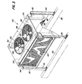
- blower and radiator device 30 which has a support device 32 which consists of two front vertical supports 34 arranged at a distance from one another and two rear, likewise vertical support supports 36.
- the rear frame part 14 of the front loader 10 consists of two horizontally extending box girders 38 and 40 which extend in the direction of travel.
- the lower end of the front and rear support brackets 34 and 36 is detachably connected to the upper flange of each box girder 38, 40.
- the two front support supports 34 are connected to one another via a vertically extending end wall 42 and the two rear support supports 36 are connected to each other by a vertically extending rear wall 44.
- a downwardly open, V-shaped base 46 which is rectangular in plan view, is connected to the front wall 42 and the rear wall 44 with its corresponding front or rear opposite ends.
- the V-shaped base 46 has opposite, approximately rectangular webs 48 and 50 which extend between the end wall 42 and the rear wall 44.
- a rectangular radiator support frame 52 is detachably connected with its lower frame part to the web 48, while a second rectangular radiator support frame 54 is connected with its lower frame part in a similar manner to the opposite web 50.
- the opposite, upright radiator support frames 52 and 54 are detachably connected at the end to the end wall 42 and the rear wall 44.
- An upper wall 56 extends between the radiator support frames 52 and 54 and is detachably connected to them. In the upper wall 56 there are two circular air outlet openings 58 and 60.
- Corresponding rectangular radiators 62 and 64 are located in the radiator support frame 52 and 54. Inside the housing formed from the front wall 42 and the rear wall 44, the bottom 46 and the upper wall 56 and the radiators 62 and 64 there is a front and rear Blower means 66 and 68 vertically below the air outlet openings 58 and 60, which draws the cooling air through the radiators 62 and 64 and discharges it vertically through the air outlet openings 58 and 60. Thus, the cooling air can flow freely, so that the pressure drop generated by the blower device 66 is relatively small and the corresponding efficiency is relatively high.
- the blower device 66 has a hollow support device 70 with a circular flange 72 which is detachably connected to the bottom 46 and correspondingly surrounds a circular opening 74.
- a hydraulic drive motor 76 is received with its upper end in the opening 74 and has an annular flange 78 which is connected to the lower side of the base 46 and is secured with corresponding screw bolts 79 so that the carrying device 70 maintains its desired position.
- the drive motor 76 has a vertical PTO shaft 80 which is connected to the lower end of a drive shaft 82, the upper part of which is rotatably received in a bearing, for example a roller bearing 84, which is provided in the carrying device 70.
- a drive pulley or a V-belt pulley 86 and an impeller 88 which is fastened to the upper end face of the V-belt pulley 86, for example by means of screw bolts.
- the blower device 68 also has a hollow support device 70 with an annular flange 92 which is detachably connected to the base 46 by means of screw bolts.
- a vertically extending drive shaft is rotatably received in the support device 90 by means of roller bearings.
- At the upper end of the drive shaft there is a V-belt pulley 94 which is drive-connected via a drive means, for example a V-belt, to the V-belt pulley 86 which is driven by the drive motor 76, which can be designed as a hydraulic motor, for example.
- a second fan wheel 89 is attached to the upper end face of the V-belt pulley 94 Screw bolts releasably connected.
- the V-belt 96 receives the necessary V-belt tension via a tensioning roller 100, which is arranged on a support arm 102 provided on the support device 32 and pivotably mounted and lies in the same horizontal plane as the V-belt 96.
- the support arm 102 is also connected to the support device 32 via a tension spring 104 in order to pull the tensioning roller in a corresponding manner against the V-belt 96.
- the drive motor 76 or its output speed is controlled as a function of the fluctuations in the coolant temperature.
- a control device is shown schematically in FIG. 4.
- the control device includes a hydraulic pump 106 which is driven by the internal combustion engine 22 and which is connected to the drive motor 76 via corresponding hydraulic lines 110.
- a pressure relief valve 108 is located between the outlet of the hydraulic pump 106 and the hydraulic line 110, which is designed as a return line.
- a temperature-dependent actuator 112 is provided between the pressure relief valve 108 and the internal combustion engine 22 and works in dependence on the coolant temperature in order to adjust the pressure at the pressure relief valve 108 and thus the output speed of the drive motor 76.
- the speed of the blower device 66 or 68 can be set to the corresponding minimum in order to reduce the noise generated by the blower device 66 or 68 to a minimum.
- blower and radiator device 30 Due to the advantageous design and arrangement of the blower and radiator device 30, it can be removed in a simple manner in order to obtain easy access to the internal combustion engine 22 for maintenance work.
- the support supports 36 and 34 from the frame part 14 and the coolant lines from the radiators 62 and 64 as well the feed and return lines of the drive motor 76 are released and then the entire blower and radiator device 30 is lifted out of the carrying device via a corresponding device.
- the blower and radiator device 30 can be provided with corresponding eyelets, which are not shown in the drawing.
Landscapes
- Engineering & Computer Science (AREA)
- Mechanical Engineering (AREA)
- General Engineering & Computer Science (AREA)
- Chemical & Material Sciences (AREA)
- Combustion & Propulsion (AREA)
- Cooling, Air Intake And Gas Exhaust, And Fuel Tank Arrangements In Propulsion Units (AREA)
Applications Claiming Priority (2)
| Application Number | Priority Date | Filing Date | Title |
|---|---|---|---|
| US06/401,780 US4757858A (en) | 1982-07-26 | 1982-07-26 | Vehicle fan and radiator assembly |
| US401780 | 1999-09-22 |
Publications (3)
| Publication Number | Publication Date |
|---|---|
| EP0100039A2 true EP0100039A2 (fr) | 1984-02-08 |
| EP0100039A3 EP0100039A3 (en) | 1985-01-16 |
| EP0100039B1 EP0100039B1 (fr) | 1987-01-21 |
Family
ID=23589203
Family Applications (1)
| Application Number | Title | Priority Date | Filing Date |
|---|---|---|---|
| EP83106981A Expired EP0100039B1 (fr) | 1982-07-26 | 1983-07-16 | Soufflerie d'air de refroidissement pour moteur à combustion interne |
Country Status (5)
| Country | Link |
|---|---|
| US (1) | US4757858A (fr) |
| EP (1) | EP0100039B1 (fr) |
| JP (1) | JPS5934415A (fr) |
| CA (1) | CA1236355A (fr) |
| DE (1) | DE3369361D1 (fr) |
Cited By (6)
| Publication number | Priority date | Publication date | Assignee | Title |
|---|---|---|---|---|
| EP0259182A3 (fr) * | 1986-09-05 | 1989-03-22 | Brookside Group Inc | Dispositif de circulation d'air |
| WO1992008042A1 (fr) * | 1990-11-01 | 1992-05-14 | Terex Corporation | Systeme modulaire et peu bruyant de refroidissement |
| GB2299158A (en) * | 1995-03-21 | 1996-09-25 | Valeo Uk | Method and apparatus for securing a fan motor and heat exchanger to a structure |
| DE19545390A1 (de) * | 1995-12-06 | 1997-06-12 | Behr Gmbh & Co | Tandemlüfter für Kühler von Kraftfahrzeugen |
| EP2361361A4 (fr) * | 2008-12-22 | 2013-11-06 | Atlas Copco Rock Drills Ab | Système de refroidissement pour refroidir au moins un fluide en circulation, et machine comprenant le système de refroidissement |
| CN119267473A (zh) * | 2024-12-10 | 2025-01-07 | 唐山昌宏科技有限公司 | 一种隔爆型电磁矿车用一体式可控制动轴 |
Families Citing this family (36)
| Publication number | Priority date | Publication date | Assignee | Title |
|---|---|---|---|---|
| US4280231A (en) * | 1979-06-14 | 1981-07-28 | Swanson Alfred B | Elbow prosthesis |
| US4825815A (en) * | 1988-01-29 | 1989-05-02 | Deere & Company | Pivotal cooling unit |
| US5067560A (en) * | 1991-02-11 | 1991-11-26 | American Standard Inc. | Condenser coil arrangement for refrigeration system |
| GB2257241B (en) * | 1991-07-03 | 1995-09-20 | Anthony Poulton | Cooling tunnel |
| US5778832A (en) * | 1997-04-14 | 1998-07-14 | Kohler Co. | Modular radiator for an engine-generator set |
| DE19731999A1 (de) * | 1997-07-25 | 1999-02-04 | Laengerer & Reich Gmbh & Co | Kühlmodul |
| JPH11269919A (ja) * | 1998-03-24 | 1999-10-05 | Shin Caterpillar Mitsubishi Ltd | 建設機械の冷却装置 |
| US6179043B1 (en) * | 1999-05-27 | 2001-01-30 | Caterpillar Inc. | Heavy vehicle radiator with center-mounted hydraulic cooling fan motor and hydraulic motor oil cooler |
| US6321830B1 (en) | 1999-12-15 | 2001-11-27 | Caterpillar Inc. | Cooling system for a work machine |
| DE10030355A1 (de) * | 2000-06-21 | 2002-01-03 | Modine Mfg Co | Kühleinrichtung für Brennkraftmaschinen |
| US6749007B2 (en) * | 2000-08-25 | 2004-06-15 | Modine Manufacturing Company | Compact cooling system with similar flow paths for multiple heat exchangers |
| US20060000429A1 (en) * | 2003-01-08 | 2006-01-05 | Stone Kevin T | Vehicle rooftop engine cooling system |
| US6910529B2 (en) * | 2003-01-08 | 2005-06-28 | Ise Corporation | Vehicle rooftop engine cooling system |
| US20080053129A1 (en) * | 2003-01-08 | 2008-03-06 | Ise Corporation | Vehicle Rooftop Engine Cooling System and Method |
| JP5044218B2 (ja) * | 2003-12-10 | 2012-10-10 | コーニンクレッカ フィリップス エレクトロニクス エヌ ヴィ | X線管用の気流束ダイレクタシステム |
| US7481287B2 (en) * | 2004-04-02 | 2009-01-27 | Deere & Company | Vehicle cooling package |
| US20070007061A1 (en) * | 2005-07-06 | 2007-01-11 | Deere & Company | Plenum cooling system |
| DE102005045052A1 (de) * | 2005-09-21 | 2007-09-20 | Deere & Company, Moline | Kühlanordnung eines Fahrzeugs |
| US9441892B2 (en) * | 2006-12-11 | 2016-09-13 | Deere & Company | Stacked heat exchanger system with swing-out heat exchangers |
| US20080142285A1 (en) * | 2006-12-18 | 2008-06-19 | Caterpillar Inc. | Airflow redirector |
| US20080178825A1 (en) * | 2007-01-31 | 2008-07-31 | Caterpillar Inc. | System and method for cooling a power source enclosure |
| US8454718B2 (en) * | 2009-03-26 | 2013-06-04 | Crown Equipment Corporation | Working vehicle having cooling system with suction device |
| DE102010010398A1 (de) * | 2010-03-05 | 2011-09-08 | GM Global Technology Operations LLC , (n. d. Ges. d. Staates Delaware) | Frontstruktur eines Kraftfahrzeugs |
| US20110277973A1 (en) * | 2010-05-17 | 2011-11-17 | Foley Jason J | Cooling Circuit With Parallel Radiators |
| US8960342B2 (en) | 2011-02-22 | 2015-02-24 | Deere & Company | Swing-out coolers and cooling fans |
| WO2012135821A2 (fr) * | 2011-04-01 | 2012-10-04 | Agco Corporation | Écoulement d'air propulseur pour système de refroidissement de véhicule de travail |
| US9133756B2 (en) * | 2011-04-01 | 2015-09-15 | Agco Corporation | Method for determining when cooling system is restricted |
| US20120298327A1 (en) * | 2011-05-25 | 2012-11-29 | Caterpillar Inc. | Cooling apparatus for controlling airflow |
| US8770329B2 (en) * | 2011-07-18 | 2014-07-08 | Caterpillar Forest Products Inc. | Engine cooling system |
| US8672071B2 (en) * | 2011-09-21 | 2014-03-18 | Deere & Company | Fluid cooler arrangement for a cooling package in a work vehicle |
| US8453777B2 (en) * | 2011-10-24 | 2013-06-04 | Deere & Company | Cooling fan duct assembly |
| CA2779475C (fr) * | 2012-05-29 | 2015-04-07 | Macdon Industries Ltd. | Tracteur de faucheuse-andaineuse avec echangeurs de chaleur paralleles pour le refroidissement du moteur et des fluides connexes |
| ITPR20120073A1 (it) * | 2012-10-31 | 2014-05-01 | Orlandi Radiatori S R L | Apparato idoneo al raffreddamento di un motore endotermico |
| US10018101B2 (en) | 2013-01-18 | 2018-07-10 | Robert D. Seligman | Cooling system and a method for its use |
| WO2014192405A1 (fr) * | 2014-03-31 | 2014-12-04 | 株式会社小松製作所 | Véhicule de travail |
| CA3009337A1 (fr) | 2018-06-26 | 2019-12-26 | Copper Core Limited | Ensemble echangeur de chaleur avec un ruban de protection thermique |
Family Cites Families (13)
| Publication number | Priority date | Publication date | Assignee | Title |
|---|---|---|---|---|
| US1650259A (en) * | 1924-11-26 | 1927-11-22 | Ljungstroms Angturbin Ab | Condenser for locomotives |
| US1752230A (en) * | 1928-02-11 | 1930-03-25 | Conrad C C Burkhardt | Cooling system for internal-combustion locomotives |
| US2317849A (en) * | 1941-01-30 | 1943-04-27 | Baldwin Locomotive Works | Locomotive |
| US2336840A (en) * | 1942-07-04 | 1943-12-14 | Gen Electric | Radiator arrangement |
| FR988869A (fr) * | 1944-01-24 | 1951-09-03 | Million Guiet Tubauto | Procédé de refroidissement des moteurs placés à l'arrière de véhicules automobiles et dispositifs pour l'application de ce procédé |
| US2897802A (en) * | 1957-07-16 | 1959-08-04 | Continental Motors Corp | Engine construction |
| DE1143676B (de) * | 1960-12-30 | 1963-02-14 | Kloeckner Humboldt Deutz Ag | Kraftmaschinensatz |
| US3203499A (en) * | 1962-06-08 | 1965-08-31 | Caterpillar Tractor Co | Cooling arrangement for supercharged engines |
| US3366167A (en) * | 1966-08-01 | 1968-01-30 | Carrier Corp | Condensing units for refrigeration systems |
| US3401605A (en) * | 1966-09-13 | 1968-09-17 | Abex Corp | Temperature responsive hydraulic system and valve means therefor |
| US3664129A (en) * | 1968-05-08 | 1972-05-23 | Hyster Co | Hydraulic cooling system |
| US3731660A (en) * | 1971-12-29 | 1973-05-08 | Gen Motors Corp | Vapor-cooled internal combustion engine |
| DD129540A1 (de) * | 1976-12-31 | 1978-01-25 | Dieter Kunze | Luftleiteinrichtung am motorkuehlsystem einer selbstfahrenden landmaschine |
-
1982
- 1982-07-26 US US06/401,780 patent/US4757858A/en not_active Expired - Fee Related
-
1983
- 1983-07-07 CA CA000431980A patent/CA1236355A/fr not_active Expired
- 1983-07-16 EP EP83106981A patent/EP0100039B1/fr not_active Expired
- 1983-07-16 DE DE8383106981T patent/DE3369361D1/de not_active Expired
- 1983-07-25 JP JP58135669A patent/JPS5934415A/ja active Pending
Cited By (10)
| Publication number | Priority date | Publication date | Assignee | Title |
|---|---|---|---|---|
| EP0259182A3 (fr) * | 1986-09-05 | 1989-03-22 | Brookside Group Inc | Dispositif de circulation d'air |
| WO1992008042A1 (fr) * | 1990-11-01 | 1992-05-14 | Terex Corporation | Systeme modulaire et peu bruyant de refroidissement |
| GB2299158A (en) * | 1995-03-21 | 1996-09-25 | Valeo Uk | Method and apparatus for securing a fan motor and heat exchanger to a structure |
| GB2299158B (en) * | 1995-03-21 | 1999-08-04 | Valeo Uk | Fan and heat exchanger support bracket |
| DE19545390A1 (de) * | 1995-12-06 | 1997-06-12 | Behr Gmbh & Co | Tandemlüfter für Kühler von Kraftfahrzeugen |
| US5826549A (en) * | 1995-12-06 | 1998-10-27 | Behr Gmbh & Co. | Tandem fan for motor-vehicle radiators |
| DE19545390C2 (de) * | 1995-12-06 | 2000-07-27 | Behr Gmbh & Co | Tandemlüfter für Kühler von Kraftfahrzeugen |
| EP2361361A4 (fr) * | 2008-12-22 | 2013-11-06 | Atlas Copco Rock Drills Ab | Système de refroidissement pour refroidir au moins un fluide en circulation, et machine comprenant le système de refroidissement |
| AU2009330784B2 (en) * | 2008-12-22 | 2014-09-18 | Atlas Copco Rock Drills Ab | Cooling system for cooling of at least one circulating fluid, and a machine comprising the cooling system |
| CN119267473A (zh) * | 2024-12-10 | 2025-01-07 | 唐山昌宏科技有限公司 | 一种隔爆型电磁矿车用一体式可控制动轴 |
Also Published As
| Publication number | Publication date |
|---|---|
| EP0100039B1 (fr) | 1987-01-21 |
| JPS5934415A (ja) | 1984-02-24 |
| CA1236355A (fr) | 1988-05-10 |
| DE3369361D1 (en) | 1987-02-26 |
| US4757858A (en) | 1988-07-19 |
| EP0100039A3 (en) | 1985-01-16 |
Similar Documents
| Publication | Publication Date | Title |
|---|---|---|
| EP0100039B1 (fr) | Soufflerie d'air de refroidissement pour moteur à combustion interne | |
| DE3853752T2 (de) | Geländefahrzeug. | |
| DE69016202T2 (de) | Lufteinlasseinrichtung für Nutzfahrzeuge. | |
| EP0515924B1 (fr) | Unité d'échangeur de chaleur-ventilateur compacte | |
| DE112013000178B3 (de) | Hydraulikbagger | |
| DE2041163C3 (de) | Motorverkleidung zur Führung von angesaugter Kühlluft für eine Brennkraftmaschine eines Mähdreschers | |
| EP0079399B1 (fr) | Dispositif de nettoyage pour nettoyer le filtre à air d'un carter d'air de refroidissement avec un radiateur comprenant un ventilateur | |
| DE4028547C2 (de) | Ölwanne für eine Brennkraftmaschine | |
| DE2618920A1 (de) | Luftfoerdereinrichtung an einem kuehler fuer brennkraftmaschinen | |
| DE60009026T2 (de) | Erdbewegungsmaschine | |
| DE2641444C2 (de) | Aggregateraum für Kraftwagen | |
| DE3635755C2 (fr) | ||
| DE2757966C2 (de) | Luft- und Abgasführung für ein schwimmfähiges Geländefahrzeug | |
| DE2502242C3 (de) | Sammelbehälter für Druckmittelflüssigkeit | |
| DE2331765C3 (de) | Anordnung eines Kraftstoffbehälters an einem Ackerschlepper | |
| DE60017036T2 (de) | Handhabungsfahrzeug für Material | |
| DE29504867U1 (de) | Kühleranordnung für ein Kraftfahrzeug, eine Baumaschine oder eine Erdbewegungsmaschine | |
| DE60314797T2 (de) | Getriebe für Förderfahrzeug | |
| DE60319630T2 (de) | Ölwanne | |
| DE2153415C2 (de) | Zweiachsiger Schlepper, insbesondere für die Landwirtschaft | |
| EP3239403B1 (fr) | Appareil de travail dorsal comprenant un moteur d'entraînement et un ventilateur entraîné par le moteur d'entraînement | |
| DE2715760C2 (de) | Ausbildung einer Luftansaug- und Verteileinrichtung für ein Kraftfahrzeug, insbesondere für ein land- oder bauwirtschaftlich nutzbares Motorfahrzeug | |
| DE2515927C2 (de) | Fahrzeug mit einer Motorverkleidung | |
| DE10340630B4 (de) | Schlangenlinienförmige Riemenanordnung für den Antrieb von Zusatzaggregaten eines Motors | |
| DE3423531C2 (fr) |
Legal Events
| Date | Code | Title | Description |
|---|---|---|---|
| PUAI | Public reference made under article 153(3) epc to a published international application that has entered the european phase |
Free format text: ORIGINAL CODE: 0009012 |
|
| AK | Designated contracting states |
Designated state(s): DE FR GB |
|
| EL | Fr: translation of claims filed | ||
| 17P | Request for examination filed |
Effective date: 19840607 |
|
| PUAL | Search report despatched |
Free format text: ORIGINAL CODE: 0009013 |
|
| AK | Designated contracting states |
Designated state(s): DE FR GB |
|
| GRAA | (expected) grant |
Free format text: ORIGINAL CODE: 0009210 |
|
| AK | Designated contracting states |
Kind code of ref document: B1 Designated state(s): DE FR GB |
|
| REF | Corresponds to: |
Ref document number: 3369361 Country of ref document: DE Date of ref document: 19870226 |
|
| ET | Fr: translation filed | ||
| PLBI | Opposition filed |
Free format text: ORIGINAL CODE: 0009260 |
|
| PLBI | Opposition filed |
Free format text: ORIGINAL CODE: 0009260 |
|
| 26 | Opposition filed |
Opponent name: KUEHLERFABRIK LAENGERER & REICH GMBH & CO. KG Effective date: 19871017 Opponent name: SUEDDEUTSCHE KUEHLERFABRIK JULIUS FR. BEHR GMBH & Effective date: 19871016 |
|
| 26 | Opposition filed |
Opponent name: J.M. VOITH GMBH Effective date: 19871021 |
|
| PG25 | Lapsed in a contracting state [announced via postgrant information from national office to epo] |
Ref country code: GB Effective date: 19880716 |
|
| RDAG | Patent revoked |
Free format text: ORIGINAL CODE: 0009271 |
|
| STAA | Information on the status of an ep patent application or granted ep patent |
Free format text: STATUS: PATENT REVOKED |
|
| 27W | Patent revoked |
Effective date: 19880813 |
|
| GBPR | Gb: patent revoked under art. 102 of the ep convention designating the uk as contracting state | ||
| GBPC | Gb: european patent ceased through non-payment of renewal fee |