EP0100095B1 - Pompe d'injection de carburant - Google Patents
Pompe d'injection de carburant Download PDFInfo
- Publication number
- EP0100095B1 EP0100095B1 EP83107341A EP83107341A EP0100095B1 EP 0100095 B1 EP0100095 B1 EP 0100095B1 EP 83107341 A EP83107341 A EP 83107341A EP 83107341 A EP83107341 A EP 83107341A EP 0100095 B1 EP0100095 B1 EP 0100095B1
- Authority
- EP
- European Patent Office
- Prior art keywords
- pump
- fuel
- chambers
- preparatory
- chamber
- Prior art date
- Legal status (The legal status is an assumption and is not a legal conclusion. Google has not performed a legal analysis and makes no representation as to the accuracy of the status listed.)
- Expired
Links
- 239000000446 fuel Substances 0.000 title claims description 82
- 238000002347 injection Methods 0.000 title claims description 29
- 239000007924 injection Substances 0.000 title claims description 29
- 238000002485 combustion reaction Methods 0.000 claims description 5
- 238000004891 communication Methods 0.000 claims description 3
- 238000011144 upstream manufacturing Methods 0.000 claims 1
- 230000006698 induction Effects 0.000 description 11
- 230000006835 compression Effects 0.000 description 6
- 238000007906 compression Methods 0.000 description 6
- 150000001875 compounds Chemical class 0.000 description 4
- 238000010276 construction Methods 0.000 description 4
- 230000002093 peripheral effect Effects 0.000 description 4
- 238000005086 pumping Methods 0.000 description 2
- 230000004308 accommodation Effects 0.000 description 1
- 230000008878 coupling Effects 0.000 description 1
- 238000010168 coupling process Methods 0.000 description 1
- 238000005859 coupling reaction Methods 0.000 description 1
- 230000000694 effects Effects 0.000 description 1
Images


Classifications
-
- F—MECHANICAL ENGINEERING; LIGHTING; HEATING; WEAPONS; BLASTING
- F02—COMBUSTION ENGINES; HOT-GAS OR COMBUSTION-PRODUCT ENGINE PLANTS
- F02M—SUPPLYING COMBUSTION ENGINES IN GENERAL WITH COMBUSTIBLE MIXTURES OR CONSTITUENTS THEREOF
- F02M59/00—Pumps specially adapted for fuel-injection and not provided for in groups F02M39/00 -F02M57/00, e.g. rotary cylinder-block type of pumps
- F02M59/20—Varying fuel delivery in quantity or timing
- F02M59/32—Varying fuel delivery in quantity or timing fuel delivery being controlled by means of fuel-displaced auxiliary pistons, which effect injection
-
- F—MECHANICAL ENGINEERING; LIGHTING; HEATING; WEAPONS; BLASTING
- F02—COMBUSTION ENGINES; HOT-GAS OR COMBUSTION-PRODUCT ENGINE PLANTS
- F02M—SUPPLYING COMBUSTION ENGINES IN GENERAL WITH COMBUSTIBLE MIXTURES OR CONSTITUENTS THEREOF
- F02M41/00—Fuel-injection apparatus with two or more injectors fed from a common pressure-source sequentially by means of a distributor
- F02M41/08—Fuel-injection apparatus with two or more injectors fed from a common pressure-source sequentially by means of a distributor the distributor and pumping elements being combined
- F02M41/14—Fuel-injection apparatus with two or more injectors fed from a common pressure-source sequentially by means of a distributor the distributor and pumping elements being combined rotary distributor supporting pump pistons
-
- F—MECHANICAL ENGINEERING; LIGHTING; HEATING; WEAPONS; BLASTING
- F02—COMBUSTION ENGINES; HOT-GAS OR COMBUSTION-PRODUCT ENGINE PLANTS
- F02M—SUPPLYING COMBUSTION ENGINES IN GENERAL WITH COMBUSTIBLE MIXTURES OR CONSTITUENTS THEREOF
- F02M41/00—Fuel-injection apparatus with two or more injectors fed from a common pressure-source sequentially by means of a distributor
- F02M41/08—Fuel-injection apparatus with two or more injectors fed from a common pressure-source sequentially by means of a distributor the distributor and pumping elements being combined
- F02M41/14—Fuel-injection apparatus with two or more injectors fed from a common pressure-source sequentially by means of a distributor the distributor and pumping elements being combined rotary distributor supporting pump pistons
- F02M41/1405—Fuel-injection apparatus with two or more injectors fed from a common pressure-source sequentially by means of a distributor the distributor and pumping elements being combined rotary distributor supporting pump pistons pistons being disposed radially with respect to rotation axis
- F02M41/1411—Fuel-injection apparatus with two or more injectors fed from a common pressure-source sequentially by means of a distributor the distributor and pumping elements being combined rotary distributor supporting pump pistons pistons being disposed radially with respect to rotation axis characterised by means for varying fuel delivery or injection timing
- F02M41/1422—Injection being effected by means of a free-piston displaced by the pressure of fuel
Definitions
- This invention relates to a fuel injection pump for internal combustion engines, and more particularly to an improvement on a fuel injection pump with preparatory chambers for metering an amount of fuel.
- a fuel injection pump in order to improve metering precision of an amount of fuel from an electromagnetic valve for metering, and to expand injection timing control range, it is necessary to supply metered fuel from the electromagnetic valve into pump chambers through metering preparatory chambers.
- the fuel injection pump comprises a rotor driven by the engine and a housing accommodating the rotor.
- the rotor two pump chambers are formed, and the housing is provided with the preparatory chambers, divided each in two parts by a free piston and solenoid valves for metering the fuel to be fed to the chambers.
- various fuel passages and switching valves are formed, and fuel from a fuel source is delivered to the engine through the solenoid valves, the preparatory chambers, the pump chambers, the various fuel passages and switching valves.
- Fuel injection pumps as known from EP-A-0 048 432, EP-A-0 059 943 and GB-A--2 012 360 do not have any preparatory chambers divided into two parts by a free piston, slidably inserted into those chambers.
- GB-A-2 017 205 discloses a fuel pumping apparatus in which a control device is provided between a feed pump and a switching means or distributor formed by a housing and a rotary cylindrical distributor member.
- the control device has a preparatory chamber and a piston therein and controls the flow rate offuel which is supplied from a feed pump into a cylinder with-a shuttle through the switching means and the control device with valves operated according to signal from a signal processing means having a transducer detecting the movement of the shuttle.
- the fuel pumping apparatus is provided with only one preparatory chamber for the cylinder.
- An object of the invention is to provide a fuel injection pump which is simpler in construction, compact and stable.
- the present invention resides in that solenoid valves for metering and supplying fuel and metering preparatory chambers are arranged such that fuel from said solenoid valves enters directly into said metering preparatory chamber.
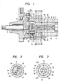
- Fig. 1 is a sectional view of an embodiment of a fuel injection pump according to the present invention
- Figs. 2 to 9 are sectional views taken along lines II-II, III-III, IV ⁇ IV, V-V, VI-VI, VII-VII, IIX-IIX and IX-IX, respectively.
- Fig. 1 showing a vertical view of a fuel injection pump for a four cylinder internal combustion engine
- the fuel injection pump is provided with a shaft 6, driven by the engine and connected to a rotor 5.
- the rotor 5 is rotatably inserted in a sleeve 18 which is fitted to a base member 16.
- the sleeve 18 and the base member 16 constitute a housing.
- the rotor 5 has an axial bore formed along an axis and plugs at both ends thereof to form a pressure chamber.
- a free piston 39 is slidably inserted and divides it into two pump chambers 24, 25.
- a stopper is provided for restricting the movement of the free piston 39 within a predetermined range.
- a feed pump 7 is provided for feeding pressurized fuel.
- the other end of the rotor 5 is connected to the shaft 6 through a coupling means.
- the base member 16 has a pair of preparatory chambers 3, 4.
- the preparatory chambers 3, 4 for measuring fuel to be fed to the pump chambers are formed in a sectional plane crossing the axis of the rotor 5 at an angle of 90° so as to extend in the perpendicular direction to the radial direction in parallel to each other.
- a free piston 14, 15 is slidably disposed thereby to divide the chamber 3, 4 into two parts.
- the preparatory chambers 3, 4 communicate with the pump chambers 24, 25 and the feed pump 7 through various passages and valves.
- Metering solenoid valves 1, 2 for measuring an amount of fuel to be injected into the preparatory chambers 3,4 are mounted on the housing so that the axes align with the preparatory chambers 3, 4 and the fuel from the solenoid valves 1, 2 enters the chambers 3, 4 directly.
- the various valves and passages formed in the rotor 5, the sleeve 18 and the base member 16 are described later.
- an expansible chamber is disposed which comprises a compression cam 26 secured to the housing 16, rollers 38 inserted recesses formed in the rotor 5, shoes 37 and plunger 36, the cam 26 has four projections corresponding to the number of the engine cylinders, and moves inwardly as the rotor 5 rotates.
- the shaft 6 has a timing gear 12 having pulse generators on the outer portions.
- a sensor 13 mounted on the housing 16 so as to face the pulse generator detects pulses from the timing gears 12 and transmits them to the solenoid valves 1, 2.
- the sleeve member 18 and base member 16 various passages are formed, and compound switching valves are formed between the sleeve 18 and the rotor 5.
- the feed pump 7, the solenoid valves 1, 2, the preparatory chambers 3, 4, the pressure chamber etc. are communicable with each other through various passages and the compound switching valves.
- the various passages and the compound switching valves are arranged as follows:
- the solenoid valve 1 and the preparatory chamber 3 are in metering fuel supply lines for injection amount control fuel, and the solenoid valve 2 and the preparatory chamber 4 are in a metering fuel supply line for injection timing control fuel.
- Fuel induction passage 8 is formed axially in the sleeve 18 from the feed pump position to VII-VII section in Fig. 7 (appears in Figs. 7, 8, 9).
- Peripheral groove 9 is formed in the periphery of the sleeve 18 in VII-VII section and communicating with said fuel induction passage 8 (Fig. 1, Fig. 7).
- Induction groove 10 is formed axially in the periphery of the sleeve 18 from VII-VII section to VI-VI section and communicates with the peripheral groove (Figs. 6, 7).
- Induction bore 11 is formed in the base member 16 and communicates with the induction groove 10 (Fig. 6).
- Discharge ports 17 are formed in the base member 16 and communicate with the preparatory chambers 3 and 4, respectively (Fig. 6).
- Discharge ports 19 are formed in the sleeve 18 and communicate with the discharge ports 10, respectively (Fig. 6).
- Discharge grooves 20 are formed in the periphery of the rotor 5 equiangularly, and communicable with the discharge ports 19 and supply passage 23.
- the discharge grooves 20 extend axially from the VI-VI section to V-V section in Fig. 5 (Figs. 6, 5).
- Discharge ports 22 are formed in the V-V section of the sleeve 18 and communicable with the discharge grooves 20, respectively (Fig. 5).
- Supply passages 23 are formed in the sleeve 18 and communicable with the discharge grooves 20 and supply grooves 28 (later described) (Fig. 6).
- the supply passage 23 is communicable with the induction bore 11 through the solenoid valve 1, 2 disposed in the induction bore 11.
- Supply ports 27 are formed in the sleeve 18, communicated with the fuel induction passage 8 and the peripheral groove 9 and communicable with the supply grooves 28 (Fig. 7).
- the supply grooves 28 are formed axially and equiangularly in the sleeve, separated from each other by 90°, extend from VII-VII section to VI-VI section, and are communicable with the discharge ports 19, the supply passages 23, the supply ports 27, and supply port 29 (Figs. 6, 7).
- the supply ports 29 are formed in the sleeve 18 and connected to supply grooves 30 and 33, respectively (Fig. 7).
- the supply groove 30 is formed in the sleeve periphery, and extend axially from VII-VII section to VIII-VIII section (Figs. 7, 8).
- Supply hole 31 is formed in the sleeve 18 and able to communicate supply holes 32 with the supply groove 30 (Fig. 8).
- Supply holes 32 are formed separated from each other by 90° in the rotor 5, and communicate with the pump chamber 25 (Fig. 1, Fig. 8).
- Supply groove 33 is formed in the sleeve 18 to extend from VII-VII section to III-III section (Fig. 1, and 3 to 7).
- Supply holes 34 are formed in the sleeve, connected to the supply groove 33 and communicable with supply holes 35, (Fig. 1, 3).
- the supply holes 35 (four) are formed equiangularly, and communicate with the pump chamber 24 (Fig. 3).
- Spill-ports 40 (four) are formed in the rotor 5, and communicate with the pump chamber 24 (Fig. 1, 4).
- Spill-passages 41 are formed in the sleeve 18, and communicate with the spill-ports 40 (Fig. 4).
- Communication passages 42 are formed in the sleeve periphery (Fig. 3, 4).
- Discharge groove 100 are formed axially in the sleeve 18 (Fig. 3 to 5).
- Delivery hole 101 is formed in the rotor 5, and communicate with the pump chamber 25 (Fig. 9).
- Delivery holes 102 (four) are formed in the sleeve and communicable with the delivery hole 101 (Fig. 9).
- Delivery ports 103 are formed in the base member 16 and communicable with the engine through pipes (not shown) (Fig. 9).
- fuel from the above-mentioned feed pump 7 is supplied to the metering solenoid valve 1 for controlling an amount of fuel to be injected into the engine and the metering solenoid valve 2 for controlling injection timing through the fuel induction passage 8, the peripheral groove 9, the induction groove 10 and the induction bore 11.
- electric pulses are delivered to the valves 1, 2 to open them, an amount of fuel corresponding to the electric pulses for opening is supplied directly into the preparatory metering chambers 3, 4 at a timing corresponding to the electric pulse.
- the timing of the valve-opening pulses, applied to the valves 1, 2 is determined by detecting signals from the timing gear 12 with the sensor 13.
- the free pistons 14 and 15 are moved left in Fig. 6, and the fuel contained in the chambers on the left of the free pistons 3, 4 is discharged into lower pressure portion (not shown) of the fuel injection pump through the discharge ports 17, the discharge ports 19, the discharge grooves 20, discharge port 22 and the discharge groove 100 whereby metering operation that the preparatory chambers 3, 4 on the right side of the free pistons 14, 15 receive fuel which has been measured is completed.
- the fuel already contained in the pump chambers 24 and 25 is pressurized by the operation of the compression cam 26.
- the metering and temporary accommodation of fuel by the solenoid valves 1, 2 and the preparatory chambers 3, 4 are effected while the compression of fuel in the pump chambers 24, 25 is carried out for injection thereof into the engine.
- the rotor 5 In order to supply the metered fuel contained in the preparatory chamber 3, 4 into the pump chambers 24, 25, the rotor 5 is rotated by 45°. At this time, the rotor 5 is shifted angularly by 45° relatively to the sleeve 18 from the position of Figs. 1 to 9. In this relative position between the rotor 5 and the sleeve 18, pressure raised by the feed pump 7 as a pressure source reaches the preparatory chamber 14, 15 on the left side of the free pistons 14,15through the fuel injection passage 8, the supply ports 27, the supply grooves 28, the discharge ports 19 and the discharge ports 17 in the mentioned order, thereby to move the free piston to the right side.
- the metered fuel contained in the preparatory chamber 3 on the right side of the free piston 14 is fed to the pump chamber 25 through the supply passages 23, the supply grooves 28, the supply ports 29, the supply groove 30, the supply hole 31 and the supply holes 32 (Fig. 6, 7, 8). Further, the metered fuel contained in the preparatory chamber 4 on the right side is fed to the pump chamber 24 through the supply passages 23, the supply grooves 28, the supply ports 29, the supply groove 33, the supply holes 34 and the supply holes 35 (Fig. 6,7,3).
- the plungers 36, the rollershoes 37 and the roller 38 are moved outward so that the chamber 24 is expanded by the volume corresponding to the amount of the fuel fed to the chamber 4, whereby the operation of supply of the metered fuel contained in the preparatory chamber 4 is carried out.
- the rotor 5 After completion of the above-mentioned fuel supply to the pump chambers 24, 25, further, the rotor 5 is rotated by 45° so that the relative position between the rotor 5 and sleeve 18 is returned to the position shown in Figs. 1 to 9. In the Figs. 1 to 9, the metering state and the compression period state are shown.
- the compression is carried out in the following manner as shown in Figs. 1 and 2, when fuel is fed to the pump chamber 24. Namely, as the rotor 5 rotates, the rollers 38 contact projections on the cam 26, whereby the rollers 38, the roller shoes 37 and the plunger 36 are pressed inside so that the fuel in the pump chamber 24 is pressurized to a high level.
- the timethefuel is pressurized is determined by the contact position between the cam 26 and the roller38.
- the contact position, that is, fuel injection timing can be controlled by an amount of the fuel fed to the pump chamber 24.
- the amount of fuel can be controlled by an amount of fuel sent from the solenoid valve 2, that is, valve opening pulse width applied to the solenoid valve 2.
- the free piston 39 is moved to the right side, and the interior of the pump chamber 25 is pressurized in turn. Therefore, the fuel in the pump chamber 25 is delivered into the combustion chamber of the engine through the delivery hole 101, the delivery holes 102, the delivery port 103, a delivery valve (not shown), a pressure pipe (not shown) and an injection valve (not shown).
- the left end of the free piston 39 is moved in the pump chamber 24 thereby to start to open the spill-port 40 which has been closed by the free piston 39.
- the fuel in the pump chamber 24 begins to be discharged through the spill ports 40, the spill passages 41 and the communication passages 42. Consequently, pressure in the pump chamber 24, in turn, pressure in the pump chamber 25 drops thereby to bring the injection of fuel into the engine to an end, and the pump chamber 24 starts to shrink by contact between the roller 38 and the projection of the cam 26, whereby the fuel discharge from the pump chamber 24 is ended. Further, in the pump chamber 25, all the amount of fuel fed into the solenoid valve 1 through the preparatory chamber 3 is fed to the engine. Therefore, the amount of fuel to be injected can be controlled precisely by opening the solenoid valve 1 according to the opening pulse width applied thereto.
- fuel passages from the solenoid valves 1, to the preparatory chambers 3,4 do not rely on passages of the compound switching valve, and the preparatory chambers 3, 4 communicate directly with the immediate downstream portions of the solenoid valves so that the fuel injection pump can be made simpler as compared with the other construction of fuel injection pump with preparatory chambers.
- the solenoid valves 1, 2 can be arranged coaxially to the preparatory chamber so that the fuel injection pump can be made more compact and stable.
Landscapes
- Engineering & Computer Science (AREA)
- Chemical & Material Sciences (AREA)
- Combustion & Propulsion (AREA)
- Mechanical Engineering (AREA)
- General Engineering & Computer Science (AREA)
- Fuel-Injection Apparatus (AREA)
- Electrical Control Of Air Or Fuel Supplied To Internal-Combustion Engine (AREA)
- High-Pressure Fuel Injection Pump Control (AREA)
Claims (4)
caractérisée en ce que les soupapes électromagnétiques (1, 2) sont disposées directement en amont des premières parties des chambres de préparation.
Applications Claiming Priority (2)
| Application Number | Priority Date | Filing Date | Title |
|---|---|---|---|
| JP57128931A JPS5920558A (ja) | 1982-07-26 | 1982-07-26 | 噴射ポンプ燃料計量供給装置 |
| JP128931/82 | 1982-07-26 |
Publications (2)
| Publication Number | Publication Date |
|---|---|
| EP0100095A1 EP0100095A1 (fr) | 1984-02-08 |
| EP0100095B1 true EP0100095B1 (fr) | 1987-05-06 |
Family
ID=14996932
Family Applications (1)
| Application Number | Title | Priority Date | Filing Date |
|---|---|---|---|
| EP83107341A Expired EP0100095B1 (fr) | 1982-07-26 | 1983-07-26 | Pompe d'injection de carburant |
Country Status (4)
| Country | Link |
|---|---|
| US (1) | US4508081A (fr) |
| EP (1) | EP0100095B1 (fr) |
| JP (1) | JPS5920558A (fr) |
| DE (1) | DE3371392D1 (fr) |
Families Citing this family (2)
| Publication number | Priority date | Publication date | Assignee | Title |
|---|---|---|---|---|
| DE3123138A1 (de) * | 1981-06-11 | 1982-12-30 | Robert Bosch Gmbh, 7000 Stuttgart | Kraftstoffeinspritzpumpe |
| JPS62182068A (ja) * | 1986-02-05 | 1987-08-10 | 旭化成株式会社 | 長尺緩衝材 |
Citations (3)
| Publication number | Priority date | Publication date | Assignee | Title |
|---|---|---|---|---|
| GB2017205A (en) * | 1978-03-22 | 1979-10-03 | Lucas Industries Ltd | Fuel Pumping Apparatus |
| EP0059943A1 (fr) * | 1981-03-11 | 1982-09-15 | Hitachi, Ltd. | Pompe d'injection de carburant pour moteurs à combustion interne |
| EP0087119A2 (fr) * | 1982-02-17 | 1983-08-31 | Hitachi, Ltd. | Pompe d'injection de carburant |
Family Cites Families (9)
| Publication number | Priority date | Publication date | Assignee | Title |
|---|---|---|---|---|
| DE1919707A1 (de) * | 1969-04-18 | 1970-11-12 | Bosch Gmbh Robert | Kraftstoffeinspritzpumpe fuer mehrzylindrige Brennkraftmaschinen |
| US3880131A (en) * | 1973-06-28 | 1975-04-29 | Bendix Corp | Fuel injection system for an internal combustion engine |
| US4185779A (en) * | 1978-01-16 | 1980-01-29 | The Bendix Corporation | Fuel injector |
| ZA791180B (en) * | 1978-03-22 | 1980-03-26 | Lucas Industries Ltd | Liquid fuel injection pump |
| GB2070151B (en) * | 1980-02-14 | 1983-09-21 | Lucas Industries Ltd | Liquid fuel injection pumping apparatus |
| DE3017276A1 (de) * | 1980-05-06 | 1981-11-12 | Robert Bosch Gmbh, 7000 Stuttgart | Kraftstoffeinspritzpumpe fuer brennkraftmaschinen |
| JPS5756660A (en) * | 1980-09-22 | 1982-04-05 | Hitachi Ltd | Fuel injection pump |
| GB2086080B (en) * | 1980-10-04 | 1984-06-13 | Lucas Industries Ltd | Control of fuel supply in ic engines |
| JPS57116139A (en) * | 1981-01-09 | 1982-07-20 | Hitachi Ltd | Emergency operating device for electrically controlled injection pump |
-
1982
- 1982-07-26 JP JP57128931A patent/JPS5920558A/ja active Pending
-
1983
- 1983-07-25 US US06/516,911 patent/US4508081A/en not_active Expired - Fee Related
- 1983-07-26 DE DE8383107341T patent/DE3371392D1/de not_active Expired
- 1983-07-26 EP EP83107341A patent/EP0100095B1/fr not_active Expired
Patent Citations (3)
| Publication number | Priority date | Publication date | Assignee | Title |
|---|---|---|---|---|
| GB2017205A (en) * | 1978-03-22 | 1979-10-03 | Lucas Industries Ltd | Fuel Pumping Apparatus |
| EP0059943A1 (fr) * | 1981-03-11 | 1982-09-15 | Hitachi, Ltd. | Pompe d'injection de carburant pour moteurs à combustion interne |
| EP0087119A2 (fr) * | 1982-02-17 | 1983-08-31 | Hitachi, Ltd. | Pompe d'injection de carburant |
Also Published As
| Publication number | Publication date |
|---|---|
| JPS5920558A (ja) | 1984-02-02 |
| EP0100095A1 (fr) | 1984-02-08 |
| DE3371392D1 (en) | 1987-06-11 |
| US4508081A (en) | 1985-04-02 |
Similar Documents
| Publication | Publication Date | Title |
|---|---|---|
| EP0643221B1 (fr) | Dispositif d'alimentation de carburant | |
| EP0048432A2 (fr) | Pompe d'injection | |
| EP0652394B1 (fr) | Soupape de commande | |
| EP0073410B1 (fr) | Pompe d'injection de combustible du type distributrice | |
| EP0413453B1 (fr) | Appareil de pompage de combustible | |
| EP0100095B1 (fr) | Pompe d'injection de carburant | |
| CA1173707A (fr) | Pompe d'injection-distribution pour moteur diesel | |
| EP0035465B1 (fr) | Pompe à combustible à distributeur rotatif | |
| CA1194374A (fr) | Dispositif de pompage de carburant | |
| JPH0350379A (ja) | 内燃機関のための燃料噴射ポンプ | |
| EP0094640B1 (fr) | Appareil de pompage pour liquide combustible | |
| US4446836A (en) | Fuel injection pumping apparatus | |
| US5613839A (en) | Variable rate pump | |
| EP0059943B1 (fr) | Pompe d'injection de carburant pour moteurs à combustion interne | |
| EP0684379B1 (fr) | Pompe distributrice d'injection de combustible | |
| US4517946A (en) | Fuel injection pump | |
| EP0232852B1 (fr) | Pompe d'injection de combustible du type distributeur | |
| EP0742364B1 (fr) | Dispositif d'alimentation en combustible | |
| CA1168530A (fr) | Pompe d'injection pour moteurs diesel | |
| EP0640760B1 (fr) | Pompe à combustible | |
| WO1985004448A1 (fr) | Restricteur de derivation pour une soupape de distribution | |
| SU1199967A1 (ru) | Распределительный топливный насос высокого давлени | |
| US3712761A (en) | Liquid fuel injection pumping apparatus | |
| JPS6157945B2 (fr) | ||
| GB2116262A (en) | A fuel injection pumping apparatus |
Legal Events
| Date | Code | Title | Description |
|---|---|---|---|
| PUAI | Public reference made under article 153(3) epc to a published international application that has entered the european phase |
Free format text: ORIGINAL CODE: 0009012 |
|
| 17P | Request for examination filed |
Effective date: 19830728 |
|
| AK | Designated contracting states |
Designated state(s): DE FR GB IT SE |
|
| GRAA | (expected) grant |
Free format text: ORIGINAL CODE: 0009210 |
|
| AK | Designated contracting states |
Kind code of ref document: B1 Designated state(s): DE FR GB IT SE |
|
| REF | Corresponds to: |
Ref document number: 3371392 Country of ref document: DE Date of ref document: 19870611 |
|
| ITF | It: translation for a ep patent filed | ||
| ET | Fr: translation filed | ||
| PLBE | No opposition filed within time limit |
Free format text: ORIGINAL CODE: 0009261 |
|
| STAA | Information on the status of an ep patent application or granted ep patent |
Free format text: STATUS: NO OPPOSITION FILED WITHIN TIME LIMIT |
|
| 26N | No opposition filed | ||
| PG25 | Lapsed in a contracting state [announced via postgrant information from national office to epo] |
Ref country code: GB Effective date: 19880726 |
|
| PG25 | Lapsed in a contracting state [announced via postgrant information from national office to epo] |
Ref country code: SE Effective date: 19880727 |
|
| GBPC | Gb: european patent ceased through non-payment of renewal fee | ||
| PG25 | Lapsed in a contracting state [announced via postgrant information from national office to epo] |
Ref country code: FR Free format text: LAPSE BECAUSE OF NON-PAYMENT OF DUE FEES Effective date: 19890331 |
|
| PG25 | Lapsed in a contracting state [announced via postgrant information from national office to epo] |
Ref country code: DE Effective date: 19890401 |
|
| REG | Reference to a national code |
Ref country code: FR Ref legal event code: ST |
|
| EUG | Se: european patent has lapsed |
Ref document number: 83107341.6 Effective date: 19890510 |