EP0100128A1 - Absorbierungsdetektoranlage - Google Patents
Absorbierungsdetektoranlage Download PDFInfo
- Publication number
- EP0100128A1 EP0100128A1 EP83201083A EP83201083A EP0100128A1 EP 0100128 A1 EP0100128 A1 EP 0100128A1 EP 83201083 A EP83201083 A EP 83201083A EP 83201083 A EP83201083 A EP 83201083A EP 0100128 A1 EP0100128 A1 EP 0100128A1
- Authority
- EP
- European Patent Office
- Prior art keywords
- frequency
- signal
- pass filter
- integrator
- low
- Prior art date
- Legal status (The legal status is an assumption and is not a legal conclusion. Google has not performed a legal analysis and makes no representation as to the accuracy of the status listed.)
- Granted
Links
Images

Classifications
-
- G—PHYSICS
- G08—SIGNALLING
- G08B—SIGNALLING SYSTEMS, e.g. PERSONAL CALLING SYSTEMS; ORDER TELEGRAPHS; ALARM SYSTEMS
- G08B13/00—Burglar, theft or intruder alarms
- G08B13/22—Electrical actuation
- G08B13/24—Electrical actuation by interference with electromagnetic field distribution
- G08B13/2402—Electronic Article Surveillance [EAS], i.e. systems using tags for detecting removal of a tagged item from a secure area, e.g. tags for detecting shoplifting
- G08B13/2405—Electronic Article Surveillance [EAS], i.e. systems using tags for detecting removal of a tagged item from a secure area, e.g. tags for detecting shoplifting characterised by the tag technology used
- G08B13/2414—Electronic Article Surveillance [EAS], i.e. systems using tags for detecting removal of a tagged item from a secure area, e.g. tags for detecting shoplifting characterised by the tag technology used using inductive tags
-
- G—PHYSICS
- G08—SIGNALLING
- G08B—SIGNALLING SYSTEMS, e.g. PERSONAL CALLING SYSTEMS; ORDER TELEGRAPHS; ALARM SYSTEMS
- G08B13/00—Burglar, theft or intruder alarms
- G08B13/22—Electrical actuation
- G08B13/24—Electrical actuation by interference with electromagnetic field distribution
- G08B13/2402—Electronic Article Surveillance [EAS], i.e. systems using tags for detecting removal of a tagged item from a secure area, e.g. tags for detecting shoplifting
- G08B13/2465—Aspects related to the EAS system, e.g. system components other than tags
- G08B13/2468—Antenna in system and the related signal processing
- G08B13/2471—Antenna signal processing by receiver or emitter
Definitions
- the invention relates to an electromagnetic detection system which, in operation, in a detection zone, by means of at least one transmission antenna coil, generates a swept-frequency interrogation field capable of being at least partly absorbed by a responder comprising a tuned circuit, if such responder is present in said detection zone, there being provided detection means coupled with said transmission antenna coil for detecting such absorption.
- Absorption takes place selectively, i.e. at a pre-determined frequency or frequency band because the responder comprises a tuned circuit. Owing to the selective absorption the energy content of the transmission circuit is modulated, which modulation can be detected by means of an envelope detector, which may be a simple diode. This envelope detector then issues a pulse in the form of the resonance curve of the tuned circuit of the responder. This form is known and so the detected pulse can be compared with the known form.
- One disadvantage of the known system is that other high-frequency signals not coming from a responder associated with the system can be detected by the transmission coil(s) and may cause the generation of a pulse at the output of the envelope detector. These signals may have frequencies located outside the sweep of the swept interrogation frequency or within this range.
- Such signals are respectively called out-band signals and in-band signals.
- a detection system of the kind described is characterized in that said detection means comprises means for eliminating spurious frequencies located outside the band of the swept frequency, said means comprising a mixer including a first input to which a signal from the transmission antenna coil is supplied, and a second input to which the output signal from a sweeping oscillator feeding said transmission antenna coil is supplied, and including an output connected with a low-pass filter.
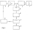
- Fig. 1 shows a known detection system as may be used, for example, for detecting theft in shops, and which is based on the absorption of energy from an interrogation field by a tuned circuit.
- the shop articles or other goods to be protected which may not be brought outside a defined area without permission, are provided with a responder with a tuned circuit 1.
- an interrogation field is generated by at least one frame antenna 2 to form a detection zone.
- the frame antenna is energized via an amplifier 3 by a known per se sweeper 4, whose frequency sweep comprises the resonance frequency of the tuned circuit 1.
- the frame antenna 2 is further connected to a circuit capable of detecting the change in voltage across the antenna, caused by the absorption of field energy by a tuned circuit l.
- This circuit comprises an envelope detector 5, an analogue filter 6, a time lock device 7 and an alarm device 8.
- Sweeper 4 is controlled by a control device 9 to provide the desired frequency sweep.
- the control device also controls the time lock device, so that it can be determined whether a detector pulse indeed occurs at the correct moment, that is to say at the moment when the swept frequency passes the resonance frequency of the tuned circuit. If this is the case, the alarm device is actuated.
- this effect can be overcome by detection with direct conversion (the homodyne principle).
- the antenna signal is supplied to a balanced mixer, and so is the transmission signal supplied by the amplifier to the antenna(s).
- the mixer forms the product of the two signals, and the frequency of the output signal is the difference between the frequency of the antenna signal and the frequency of the transmission signal.
- Out-band signals lead to relatively high frequencies of the output signal from the mixer, and can be removed in a simple manner by means of a low-pass filter.
- Fig. 2 shows diagrammatically a system arranged to suppress the effects of out-band signals and, as will be explained hereinafter, the effects of spurious in-band signals.
- Fig. 2 again shows an antenna device 2, consisting of one or more antennas, for example frame antennas, which device is fed via an amplifier 3 with the signal from a high-frequency sweeper 4, whose frequency continuously varies over a frequency range comprising the resonance frequency of the tuned circuit 1, and this in such a manner that even when there is a spread in the resonance frequency of the tuned circuit as a result of tolerances in the components, these frequencies still fall amply within the frequency sweep of the sweeper.
- an antenna device 2 consisting of one or more antennas, for example frame antennas, which device is fed via an amplifier 3 with the signal from a high-frequency sweeper 4, whose frequency continuously varies over a frequency range comprising the resonance frequency of the tuned circuit 1, and this in such a manner that even when there is a spread in the resonance frequency of the tuned circuit as a result of tolerances in the components, these frequencies still fall amply within the frequency sweep of the sweeper.
- the output signal from the amplifier is supplied via a duplexer 10 to the antenna(s).
- the duplexer is in addition, if desired via an attenuator 11, connected to a mixer 12 in order to supply the antenna signal to the mixer.
- a tuned circuit 1 is present in the detection zone created by the antenna device in the form of an interrogation field, at the moments when the swept frequency of the interrogation field passes the resonance frequency of the tuned circuit, the antenna device and the tuned circuit become magnetically coupled in such a - manner that the tuned circuit absorbs energy from the interrogation field. As a result the voltage across the antenna coil(s) is decreased.
- the voltage across the antenna coil(s) temporarily decreases each time when the field frequency passes the resonance frequency of the tuned circuit 1.
- This in practice, modulates the antenna signal in amplitude, to produce side-band frequency components relative to the field frequency.
- the mixer receives at a first input 13 a signal comprising the field frequency and two side-band frequencies.
- the mixer receives at a second input 14, via a phase compensation network 15, directly the output signal from the sweeper.
- the output signal from the mixer then comprises the side-band frequency components transformed to a carrier wave frequency of zero Herz (direct conversion).
- the output signal from the mixer may further comprise out-band signals originating from outside the system. After the direct conversion these spurious signals give rise to high-frequency signals, which are removed by means of a low-pass filter 16.
- Low-pass filter 16 is followed by a gating circuit 17, which is controlled by a control device 9 which also controls the sweeper. Gating circuit 17 is enabled by the control device each time when the swept oscillator frequency passes the resonance frequency of the tuned circuit.
- the gating circuit 17 should be conductive in the part-periods of the sine form for which angle Q is between -45° and+45° and between 135° and 225°.
- the signal passed by the gating circuit is supplied to an amplifier 18, which is adjustable to control the sensitiveness of the system.
- the output signal from the amplifier is supplied to a discriminator filter device 19, serving to separate signals from a tuned circuit 1 from spurious signals having a frequency within the sweep of the sweeper (in-band noise).
- the discriminator filter device operates as follows.
- a spurious signal for example a radio signal
- the mixer issues an output signal with a frequency that is the difference between the spurious frequency fi and the frequency of the sweeper fo.
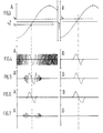
- this frequency difference will first decrease to zero Herz and then increase again (see Figs. 3A and 4A).
- the low-pass filter 16 is a barrier to signals having higher frequencies, so that the signal shown in Fig. 5A remains at the output of the mixer.
- Figs 3B, 4B and 5B show, in comparison with a spurious signal, a signal fw coming from a tuned circuit 1.
- the spurious signal will exhibit some excursions with a higher frequency than a signal coming from a responder.
- the higher-frequency excursions are separated from the low-frequency excursions.
- a low-pass filter 20 and a parallel-connected high-pass filter 21 are provided in the discriminator filter device. In this way a separation is effected between a signal from a responder and a spurious radio signal.
- Figs. 6A and 6B show the output signal from the low-pass filter 20 for a spurious signal and a signal from a responder, respectively.
- Figs. 7A and 7B show the corresponding output signals from the high-pass filter 21.
- spurious signals such as noise, pulse-shaped interference, etc.
- filters 20 and 21 are provided with rectifiers 20a and 21a.
- the two D.C. voltages are supplied to an integrator circuit 22 in such a manner that the integrator output voltage is going to increase as a result of low-frequency signals.
- Signals from the high-frequency channel. of the discriminator filter cause the integrator output voltage to decrease, however, and this in such a manner that when both signal components appear the integrator output voltage also decreases.
- the integrator is followed by a voltage comparator 23, which produces an actuating pulse to an alarm device 24 as soon as the output voltage exceeds a pre-determined threshold value.
- the rise time of the integrator is preferably such that about ten sweep periods in which a signal from a responder is received are required to actuate the alarm signal.
Landscapes
- Engineering & Computer Science (AREA)
- Physics & Mathematics (AREA)
- Signal Processing (AREA)
- Automation & Control Theory (AREA)
- Computer Security & Cryptography (AREA)
- Electromagnetism (AREA)
- General Physics & Mathematics (AREA)
- Radar Systems Or Details Thereof (AREA)
- Burglar Alarm Systems (AREA)
Applications Claiming Priority (2)
| Application Number | Priority Date | Filing Date | Title |
|---|---|---|---|
| NL8202951 | 1982-07-21 | ||
| NL8202951A NL8202951A (nl) | 1982-07-21 | 1982-07-21 | Absorptiedetectiestelsel. |
Publications (2)
| Publication Number | Publication Date |
|---|---|
| EP0100128A1 true EP0100128A1 (de) | 1984-02-08 |
| EP0100128B1 EP0100128B1 (de) | 1986-12-30 |
Family
ID=19840068
Family Applications (1)
| Application Number | Title | Priority Date | Filing Date |
|---|---|---|---|
| EP83201083A Expired EP0100128B1 (de) | 1982-07-21 | 1983-07-21 | Absorbierungsdetektoranlage |
Country Status (4)
| Country | Link |
|---|---|
| US (1) | US4686517A (de) |
| EP (1) | EP0100128B1 (de) |
| DE (1) | DE3368785D1 (de) |
| NL (1) | NL8202951A (de) |
Cited By (5)
| Publication number | Priority date | Publication date | Assignee | Title |
|---|---|---|---|---|
| EP0242901A1 (de) * | 1986-03-24 | 1987-10-28 | N.V. Nederlandsche Apparatenfabriek NEDAP | Elektromagnetische Detektionsanlage mit Falschalarmunterdrückung |
| EP0251210A1 (de) * | 1986-06-25 | 1988-01-07 | Media Security Incorporated And Associates | Sicherheitssystem zum Datenschutz |
| EP0387970A1 (de) * | 1989-03-17 | 1990-09-19 | N.V. Nederlandsche Apparatenfabriek NEDAP | Ladendiebstahlnachweissystem vom Transmissionstyp |
| EP0608961A1 (de) * | 1993-01-28 | 1994-08-03 | N.V. Nederlandsche Apparatenfabriek NEDAP | Verfahren und System zur Detektierung von Resonanzeffekten eines Etiketts in einem gewobbelten Abfragefeld mittels Einseitenbanddemodulation |
| US5373301A (en) * | 1993-01-04 | 1994-12-13 | Checkpoint Systems, Inc. | Transmit and receive antenna having angled crossover elements |
Families Citing this family (13)
| Publication number | Priority date | Publication date | Assignee | Title |
|---|---|---|---|---|
| NL8700388A (nl) * | 1987-02-17 | 1988-09-16 | Nedap Nv | Flexibele identificatielabel. |
| US5103209A (en) * | 1989-01-09 | 1992-04-07 | Checkpoint Systems, Inc. | Electronic article surveillance system with improved differentiation |
| AU631170B2 (en) * | 1989-01-09 | 1992-11-19 | Checkpoint Systems, Inc. | Electronic article surveillance system with improved differentiation |
| CH681051A5 (de) * | 1989-03-22 | 1992-12-31 | Actron Entwicklungs Ag | |
| US4975968A (en) * | 1989-10-27 | 1990-12-04 | Spatial Dynamics, Ltd. | Timed dielectrometry surveillance method and apparatus |
| US5349339A (en) * | 1992-04-07 | 1994-09-20 | Actron Entwicklungs Ag | Apparatus for the detection of labels employing subtraction of background signals |
| US5353011A (en) * | 1993-01-04 | 1994-10-04 | Checkpoint Systems, Inc. | Electronic article security system with digital signal processing and increased detection range |
| US5521600A (en) * | 1994-09-06 | 1996-05-28 | The Regents Of The University Of California | Range-gated field disturbance sensor with range-sensitivity compensation |
| US5682164A (en) * | 1994-09-06 | 1997-10-28 | The Regents Of The University Of California | Pulse homodyne field disturbance sensor |
| US5625341A (en) * | 1995-08-31 | 1997-04-29 | Sensormatic Electronics Corporation | Multi-bit EAS marker powered by interrogation signal in the eight MHz band |
| US8452868B2 (en) | 2009-09-21 | 2013-05-28 | Checkpoint Systems, Inc. | Retail product tracking system, method, and apparatus |
| US8508367B2 (en) | 2009-09-21 | 2013-08-13 | Checkpoint Systems, Inc. | Configurable monitoring device |
| CN109379150A (zh) * | 2018-11-27 | 2019-02-22 | 中国电力科学研究院有限公司 | 一种用于检测电力无线专网上行干扰的系统及方法 |
Citations (5)
| Publication number | Priority date | Publication date | Assignee | Title |
|---|---|---|---|---|
| US3798642A (en) * | 1972-09-27 | 1974-03-19 | Microlab Fxr | Recognition system |
| US3868669A (en) * | 1973-04-13 | 1975-02-25 | Knogo Corp | Reduction of false alarms in electronic theft detection systems |
| FR2384306A1 (fr) * | 1977-03-14 | 1978-10-13 | Lichtblau George | Circuit d'elimination de frequences de battement pour dispositifs electroniques de securite |
| GB1570877A (en) * | 1975-11-14 | 1980-07-09 | Nedap Nv | Identification system |
| WO1982001255A1 (en) * | 1980-09-30 | 1982-04-15 | J Vandebult | Fm/am electronic security system |
Family Cites Families (4)
| Publication number | Priority date | Publication date | Assignee | Title |
|---|---|---|---|---|
| US3810147A (en) * | 1971-12-30 | 1974-05-07 | G Lichtblau | Electronic security system |
| GB1500289A (en) * | 1974-06-03 | 1978-02-08 | Rca Corp | Homodyne communication system |
| US4023167A (en) * | 1975-06-16 | 1977-05-10 | Wahlstrom Sven E | Radio frequency detection system and method for passive resonance circuits |
| US4499564A (en) * | 1980-08-20 | 1985-02-12 | Secom Co., Ltd. | Pattern comparison ultrasonic surveillance system with noise suppression |
-
1982
- 1982-07-21 NL NL8202951A patent/NL8202951A/nl not_active Application Discontinuation
-
1983
- 1983-07-21 EP EP83201083A patent/EP0100128B1/de not_active Expired
- 1983-07-21 DE DE8383201083T patent/DE3368785D1/de not_active Expired
-
1984
- 1984-05-30 US US06/615,240 patent/US4686517A/en not_active Expired - Fee Related
Patent Citations (5)
| Publication number | Priority date | Publication date | Assignee | Title |
|---|---|---|---|---|
| US3798642A (en) * | 1972-09-27 | 1974-03-19 | Microlab Fxr | Recognition system |
| US3868669A (en) * | 1973-04-13 | 1975-02-25 | Knogo Corp | Reduction of false alarms in electronic theft detection systems |
| GB1570877A (en) * | 1975-11-14 | 1980-07-09 | Nedap Nv | Identification system |
| FR2384306A1 (fr) * | 1977-03-14 | 1978-10-13 | Lichtblau George | Circuit d'elimination de frequences de battement pour dispositifs electroniques de securite |
| WO1982001255A1 (en) * | 1980-09-30 | 1982-04-15 | J Vandebult | Fm/am electronic security system |
Cited By (5)
| Publication number | Priority date | Publication date | Assignee | Title |
|---|---|---|---|---|
| EP0242901A1 (de) * | 1986-03-24 | 1987-10-28 | N.V. Nederlandsche Apparatenfabriek NEDAP | Elektromagnetische Detektionsanlage mit Falschalarmunterdrückung |
| EP0251210A1 (de) * | 1986-06-25 | 1988-01-07 | Media Security Incorporated And Associates | Sicherheitssystem zum Datenschutz |
| EP0387970A1 (de) * | 1989-03-17 | 1990-09-19 | N.V. Nederlandsche Apparatenfabriek NEDAP | Ladendiebstahlnachweissystem vom Transmissionstyp |
| US5373301A (en) * | 1993-01-04 | 1994-12-13 | Checkpoint Systems, Inc. | Transmit and receive antenna having angled crossover elements |
| EP0608961A1 (de) * | 1993-01-28 | 1994-08-03 | N.V. Nederlandsche Apparatenfabriek NEDAP | Verfahren und System zur Detektierung von Resonanzeffekten eines Etiketts in einem gewobbelten Abfragefeld mittels Einseitenbanddemodulation |
Also Published As
| Publication number | Publication date |
|---|---|
| US4686517A (en) | 1987-08-11 |
| NL8202951A (nl) | 1984-02-16 |
| DE3368785D1 (en) | 1987-02-05 |
| EP0100128B1 (de) | 1986-12-30 |
Similar Documents
| Publication | Publication Date | Title |
|---|---|---|
| EP0100128B1 (de) | Absorbierungsdetektoranlage | |
| CA1107835A (en) | Surveillance method and system with electromagnetic carrier and plural range limiting signals | |
| US3707711A (en) | Electronic surveillance system | |
| US3895368A (en) | Surveillance system and method utilizing both electrostatic and electromagnetic fields | |
| US4551712A (en) | Electronic detection system for detecting a responder including a frequency divider | |
| US3031643A (en) | Transmission line fence burglar alarm | |
| US3314066A (en) | Method and apparatus for detecting the entrance of an object into a region being monitored | |
| US3518546A (en) | Harmonic communication and navigation system | |
| GB2078469A (en) | Improvements in surveillance systems for preventing pilferage | |
| US3182312A (en) | Vehicle detection and counting system | |
| US3863240A (en) | Electromagnetic intrusion detection system | |
| US3691559A (en) | Aircraft collision warning system | |
| US2517549A (en) | Pulse radar system for detecting moving objects | |
| US2436846A (en) | Glide path system for aircraft | |
| US2862203A (en) | Arrangement in a radar station | |
| US3958244A (en) | Transmitter output monitor | |
| US4371981A (en) | Spectral squelch | |
| NL9001414A (nl) | Radarapparaat met storingsindicator en ontvanginrichting met storingsindicator. | |
| GB1505081A (en) | System for the identification of a road vehicle travelling along a predetermined route | |
| US3257659A (en) | Counter-detection system | |
| US3800231A (en) | Doppler tracker receiver | |
| CA1225715A (en) | Field disturbance detection system | |
| US3982243A (en) | Device for transmission of information from an information emitter to an information seeker | |
| RU2138855C1 (ru) | Элемент сигнализации | |
| US2480171A (en) | Pulse receiver system for improved target tracking |
Legal Events
| Date | Code | Title | Description |
|---|---|---|---|
| PUAI | Public reference made under article 153(3) epc to a published international application that has entered the european phase |
Free format text: ORIGINAL CODE: 0009012 |
|
| AK | Designated contracting states |
Designated state(s): BE DE FR GB NL |
|
| 17P | Request for examination filed |
Effective date: 19840703 |
|
| GRAA | (expected) grant |
Free format text: ORIGINAL CODE: 0009210 |
|
| AK | Designated contracting states |
Kind code of ref document: B1 Designated state(s): BE DE FR GB NL |
|
| REF | Corresponds to: |
Ref document number: 3368785 Country of ref document: DE Date of ref document: 19870205 |
|
| ET | Fr: translation filed | ||
| PLBE | No opposition filed within time limit |
Free format text: ORIGINAL CODE: 0009261 |
|
| STAA | Information on the status of an ep patent application or granted ep patent |
Free format text: STATUS: NO OPPOSITION FILED WITHIN TIME LIMIT |
|
| 26N | No opposition filed | ||
| PGFP | Annual fee paid to national office [announced via postgrant information from national office to epo] |
Ref country code: GB Payment date: 19940624 Year of fee payment: 12 |
|
| PGFP | Annual fee paid to national office [announced via postgrant information from national office to epo] |
Ref country code: FR Payment date: 19940721 Year of fee payment: 12 |
|
| PGFP | Annual fee paid to national office [announced via postgrant information from national office to epo] |
Ref country code: DE Payment date: 19940726 Year of fee payment: 12 Ref country code: BE Payment date: 19940726 Year of fee payment: 12 |
|
| PGFP | Annual fee paid to national office [announced via postgrant information from national office to epo] |
Ref country code: NL Payment date: 19940731 Year of fee payment: 12 |
|
| PG25 | Lapsed in a contracting state [announced via postgrant information from national office to epo] |
Ref country code: GB Effective date: 19950721 |
|
| PG25 | Lapsed in a contracting state [announced via postgrant information from national office to epo] |
Ref country code: BE Effective date: 19950731 |
|
| BERE | Be: lapsed |
Owner name: N.V. NEDERLANDSCHE APPARATENFABRIEK NEDAP Effective date: 19950731 |
|
| PG25 | Lapsed in a contracting state [announced via postgrant information from national office to epo] |
Ref country code: NL Effective date: 19960201 |
|
| GBPC | Gb: european patent ceased through non-payment of renewal fee |
Effective date: 19950721 |
|
| NLV4 | Nl: lapsed or anulled due to non-payment of the annual fee |
Effective date: 19960201 |
|
| PG25 | Lapsed in a contracting state [announced via postgrant information from national office to epo] |
Ref country code: DE Effective date: 19960402 |
|
| PG25 | Lapsed in a contracting state [announced via postgrant information from national office to epo] |
Ref country code: FR Effective date: 19960430 |
|
| REG | Reference to a national code |
Ref country code: FR Ref legal event code: ST |
|
| REG | Reference to a national code |
Ref country code: FR Ref legal event code: ST |
|
| REG | Reference to a national code |
Ref country code: FR Ref legal event code: ST |