EP0100143A1 - Magasin pour des cartons plats, des feuilles prépliées etc. - Google Patents
Magasin pour des cartons plats, des feuilles prépliées etc. Download PDFInfo
- Publication number
- EP0100143A1 EP0100143A1 EP19830303584 EP83303584A EP0100143A1 EP 0100143 A1 EP0100143 A1 EP 0100143A1 EP 19830303584 EP19830303584 EP 19830303584 EP 83303584 A EP83303584 A EP 83303584A EP 0100143 A1 EP0100143 A1 EP 0100143A1
- Authority
- EP
- European Patent Office
- Prior art keywords
- cartons
- magazine
- carton
- conveyor
- cam
- Prior art date
- Legal status (The legal status is an assumption and is not a legal conclusion. Google has not performed a legal analysis and makes no representation as to the accuracy of the status listed.)
- Granted
Links
- 230000007246 mechanism Effects 0.000 claims abstract description 17
- 230000033001 locomotion Effects 0.000 claims description 44
- 238000011144 upstream manufacturing Methods 0.000 claims description 17
- 238000012546 transfer Methods 0.000 claims description 12
- 230000000694 effects Effects 0.000 claims description 4
- 239000011295 pitch Substances 0.000 claims 2
- 230000001133 acceleration Effects 0.000 description 4
- 238000013461 design Methods 0.000 description 4
- 238000006073 displacement reaction Methods 0.000 description 4
- 230000008859 change Effects 0.000 description 3
- 230000003247 decreasing effect Effects 0.000 description 3
- 230000001154 acute effect Effects 0.000 description 2
- 238000013459 approach Methods 0.000 description 2
- 230000007423 decrease Effects 0.000 description 2
- 238000000151 deposition Methods 0.000 description 2
- 238000000605 extraction Methods 0.000 description 2
- 230000000717 retained effect Effects 0.000 description 2
- 230000009471 action Effects 0.000 description 1
- 230000002411 adverse Effects 0.000 description 1
- 238000000429 assembly Methods 0.000 description 1
- 230000000712 assembly Effects 0.000 description 1
- 238000005452 bending Methods 0.000 description 1
- 238000006243 chemical reaction Methods 0.000 description 1
- 238000004891 communication Methods 0.000 description 1
- 238000012937 correction Methods 0.000 description 1
- 230000003292 diminished effect Effects 0.000 description 1
- 230000005484 gravity Effects 0.000 description 1
- 238000000034 method Methods 0.000 description 1
- 238000012986 modification Methods 0.000 description 1
- 230000004048 modification Effects 0.000 description 1
- 208000029278 non-syndromic brachydactyly of fingers Diseases 0.000 description 1
- 230000008569 process Effects 0.000 description 1
Images



Classifications
-
- B—PERFORMING OPERATIONS; TRANSPORTING
- B65—CONVEYING; PACKING; STORING; HANDLING THIN OR FILAMENTARY MATERIAL
- B65H—HANDLING THIN OR FILAMENTARY MATERIAL, e.g. SHEETS, WEBS, CABLES
- B65H3/00—Separating articles from piles
- B65H3/42—Separating articles from piles by two or more separators mounted for movement with, or relative to, rotary or oscillating bodies
-
- B—PERFORMING OPERATIONS; TRANSPORTING
- B31—MAKING ARTICLES OF PAPER, CARDBOARD OR MATERIAL WORKED IN A MANNER ANALOGOUS TO PAPER; WORKING PAPER, CARDBOARD OR MATERIAL WORKED IN A MANNER ANALOGOUS TO PAPER
- B31B—MAKING CONTAINERS OF PAPER, CARDBOARD OR MATERIAL WORKED IN A MANNER ANALOGOUS TO PAPER
- B31B2100/00—Rigid or semi-rigid containers made by folding single-piece sheets, blanks or webs
-
- B—PERFORMING OPERATIONS; TRANSPORTING
- B31—MAKING ARTICLES OF PAPER, CARDBOARD OR MATERIAL WORKED IN A MANNER ANALOGOUS TO PAPER; WORKING PAPER, CARDBOARD OR MATERIAL WORKED IN A MANNER ANALOGOUS TO PAPER
- B31B—MAKING CONTAINERS OF PAPER, CARDBOARD OR MATERIAL WORKED IN A MANNER ANALOGOUS TO PAPER
- B31B2120/00—Construction of rigid or semi-rigid containers
- B31B2120/30—Construction of rigid or semi-rigid containers collapsible; temporarily collapsed during manufacturing
-
- B—PERFORMING OPERATIONS; TRANSPORTING
- B31—MAKING ARTICLES OF PAPER, CARDBOARD OR MATERIAL WORKED IN A MANNER ANALOGOUS TO PAPER; WORKING PAPER, CARDBOARD OR MATERIAL WORKED IN A MANNER ANALOGOUS TO PAPER
- B31B—MAKING CONTAINERS OF PAPER, CARDBOARD OR MATERIAL WORKED IN A MANNER ANALOGOUS TO PAPER
- B31B50/00—Making rigid or semi-rigid containers, e.g. boxes or cartons
- B31B50/02—Feeding or positioning sheets, blanks or webs
- B31B50/04—Feeding sheets or blanks
- B31B50/06—Feeding sheets or blanks from stacks
- B31B50/062—Feeding sheets or blanks from stacks from the underside of a magazine
-
- B—PERFORMING OPERATIONS; TRANSPORTING
- B31—MAKING ARTICLES OF PAPER, CARDBOARD OR MATERIAL WORKED IN A MANNER ANALOGOUS TO PAPER; WORKING PAPER, CARDBOARD OR MATERIAL WORKED IN A MANNER ANALOGOUS TO PAPER
- B31B—MAKING CONTAINERS OF PAPER, CARDBOARD OR MATERIAL WORKED IN A MANNER ANALOGOUS TO PAPER
- B31B50/00—Making rigid or semi-rigid containers, e.g. boxes or cartons
- B31B50/74—Auxiliary operations
- B31B50/76—Opening and distending flattened articles
- B31B50/80—Pneumatically
- B31B50/804—Pneumatically using two or more suction devices on a rotating element
-
- B—PERFORMING OPERATIONS; TRANSPORTING
- B65—CONVEYING; PACKING; STORING; HANDLING THIN OR FILAMENTARY MATERIAL
- B65H—HANDLING THIN OR FILAMENTARY MATERIAL, e.g. SHEETS, WEBS, CABLES
- B65H2403/00—Power transmission; Driving means
- B65H2403/50—Driving mechanisms
- B65H2403/54—Driving mechanisms other
- B65H2403/543—Driving mechanisms other producing cycloids
Definitions
- This invention relates to apparatus for transferring articles from one station to another, and particularly, the invention relates to apparatus for feeding flat folded cartons from a magazine, opening them and depositing them into transport lugs on a continuously-moving conveyor. While the invention is particularly applicable to use with cartoners and leaflet feeders, it should be understood that the principles of the invention can be applied to other areas where articles must be transferred from station to station.
- Another objective of the present invention has been to provide a carton feeder employing a modification of a conventional hypocycloidal motion wherein the suction cups carried as part of rotating planetary elements rotate at non-uniform speeds during each revolution of the carrier, -the non-uniform speeds imparting to the cups motions which enable the cartons to be picked up from a stationary magazine and deposited into continuously-moving transport lugs.
- a rotating carrier having at least one planetary member rotatably mounted in the carrier.
- the planetary member carries at least one suction cup for picking up the carton and carries a plurality of cam follower rollers.
- a stationary, generally circular, cam is mounted adjacent the carrier for engagement with the follower rollers.
- the cam consists of a plurality of pockets of non-uniform pitch which cooperate with the rollers to cause the suction cups to engage the cartons with a conventional straight-in and straightout component of motion and thereafter to cause the suction cups to descend into the space between the lugs of the transport conveyor in a generally U-shaped path having a substantial horizontal component of motion.
- the U-shaped path permits the deposit of the carton to occur over a period of about twice the length of time which would be permitted by conventional hypocycloidal motion.
- the apparatus of the present invention permits an operation at substantially greater speeds than would be possible with a conventional hypocycloidal motion while reliably opening cartons into a tubular shape as they are brought into engagement with the transport lugs.
- Another objective of the present invention has been to provide for the erecting of the carton as it is introduced into the transport lugs with minimal or no requirement of additional elements such as guides and the like.
- This objective is attained in part by the use of the combined suction cup and channel-shaped member described and claimed in U .S. patent of Hughes, No. 4,178,839, but additionally and importantly, through the path of movement of the suction cup with respect to the transport lugs so that as the suction cups convey the cartons into the space between the transport lugs, a trailing edge of the carton is aligned with and against the trailing transport lugs and the carton is gradually opened to an erected tubular form of rectangular cross section.
- Another objective of the invention has been to provide an improved magazine which permits the loading of a very large supply of cartons upstream of the leading carton without applying any substantial pressure on the leading carton such as would require stops and the like to be sufficiently engaged to prevent the discharge of cartons due to pressure of the upstream supply and which therefore makes difficult the withdrawal of the cartons because of their being clamped behind such stops by such upstream supply pressure.
- the magazine is provided, at its discharge end, with a choke formed by two spaced parallel guides, the guides being spaced apart a distance less than the dimension between the folded edges of the carton in the magazine.
- One edge, the leading edge, of each carton in the choke will tend to slide toward the discharge end of the magazine. Sliding out of the magazine is resisted by a small detent at the discharge end of the magazine.
- the opposite edge will have its forward movement blocked by its engagement with the guide, and it is here that the pressure of all of the upstream cartons is absorbed.
- pins or rods are positioned immediately past the downstream end of the choke to engage the carton flaps to hold them lightly and only as insurance against inadvertent discharge from the magazine. As cartons are withdrawn from the magazine, the upstream cartons will slide past the choke and will be retained only lightly by the flap- engaging pins.
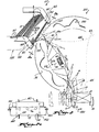
- the apparatus includes a frame 10.
- An endless transport conveyor 11 is mounted on the frame and carries a series of leading transport lugs 12 and trailing transport lugs 13 which create receptacles into which the opened carton is to be deposited.
- the cartons are indicated at 15 and are stacked in a magazine 20.
- the transfer mechanism 22 is mounted on the frame and has a rotating planetary carrier 25.
- a plurality of planet nembers 26 are rotatably mounted on the carrier 25.
- Each rotary member has a shaft 28 having fixed to it cam rollers 29.
- the cam rollers cooperate with fixed cams 30 which are mounted on the frame.
- An arm 35 is mounted on each shaft 28 and carries a suction cup 36.
- the carrier 25 is rotated in a counterclockwise direction as viewed in Fig. 1.
- the followers 29 moving along the cam 30 cause the suction cups to move in a path shown by the broken line 40.
- the suction cup moves substantially straight into the magazine to engage the leadir.g carton 15 substantially perpendicularly to the plane of the carton.
- the suction cup withdraws generally perpendicularly to the plane of the carton carrying the carton with it.
- the carton is partially open as shown in Fig. 2 at 15a through the combination of the channelshaped element 42 and the suction cup 36 as shown in .
- the suction cup In the descent of the suction cup in between the transport lugs, the suction cup follows a generally U-shaped path indicated at 45. While in the U-shaped path, the vacuum cup has a velocity component of sustantial magnitude in a direction the same as and parallel to the direction of the continuously-moving transport conveyor and provides a substantial portion of the carton cycle. For a carton having a width of two inches and a length of six inches in the direction of the transport lugs, about 145° of cycle time is available for deposit of the carton to permit the carton to be opened and deposited between the lugs. A full cartoner cycle is considered to be 360°.
- the transfer mechanism is best illustrated in the cross-sectional view of Fig. 3.
- the transfer mechanism 22 is mounted on a frame 10 fixed to the cartoner.
- the carrier 25 is mounted on a shaft 50, the shaft being supported by bearings in journal 51 of the frame 10.
- a sprocket 52 is mounted on one end of the shaft 50 and has a chain 53 connecting it via gear box 54 to the main drive of the cartoner so that it is rotated in synchronism with the components of the cartoner.
- the carrier 25 is mounted at the other end of the shaft 50.
- the carrier is formed of an inner plate 55 and an outer plate 56 which have a hub 57 sandwiched between them, the whole assembly being bolted together by a plurality of axially-extending bolts 58.
- Each planet member 26 is equiangularly and equiradially spaced around the carrier 25.
- the sleeve 61 is rotatably mounted within the plates 55 and 56 by bearings 62
- the inner tube 60 has an extension 63 to which one or more suction cup assemblies 64 are secured, three being illustrated.
- the sleeve 61 has annular flanges or supports 65 to which three equiangularly spaced outer rollers 66 are mounted and three equiangularly spaced inner roller 67 are mounted.
- the inner rollers and outer rollers are annularly spaced from each other by an angle of 60°. (One trio of these rollers is shown as 29 in Fig. 1.)
- rollers 67 ride and an outer cam track 69 on which the outer rollers 66 ride.
- the combination of six rollers cooperating with two cam tracks provides assurance that at any portion of the excursion of the carrier throughout its 360° rotation, at least two rollers will be in engagement with cam surfaces to keep the planet n.ember positively engaged with the cam surfaces.
- Vacuum is selectively applied to the suction cups between the point a.t which they pick up a carton from the magazine and the point at which they have completed their deposit of the opened carton between the transport lugs.
- the vacuum cups are connected through flexible tubes 70 to a transverse bore 71 in the shaft 28.
- the transverse bore is connected to an axial bore 72 in the inner tube 60.
- a rotary union connection 74 has a passageway 75 connected to the bore 72.
- the passageway 75 is connected via a hose to a passage 73 of to an annular ring 76 fixed to the inner plate 55.
- the passageway 73 terminates in an axial bore 77 which communicates with an arcuate channel 78 formed in an annular ring 79 which is fixed to the frame 10.
- the arcuate channel 78 has a circumferential dimension long enough to provide the communication of the vacuum to the suction cup during the period that it moves from the magazine 20 to the transport conveyor 11.
- the channel 78 is connected by a passageway 80 to a vacuum source 81.
- the chain 53 is connected to a drive sprocket 85 which is mounted on the gear box 54 which is driven in turn by a shaft 87 connected to the main cartoner drive mechanism.
- the shape of the inner and outer cams 68 and 69, respectively, is important. While different cam designs can be created to accomplish the desired functions of the present apparatus by those skilled in the art of cam design, it is critically important that the cam and follower relationship be such as to impart a non-uniform rotary motion to the orbiting planetary members as they make their excursion.
- the transfer mechanism is designed to pick a carton from a fixed magazine and while moving it into the space between continuously-moving transport lugs to open it.
- the apparatus might pick an article from a continuously-moving supply and deposit it into a fixed receptacle.
- the cam surface would be different but would not depart from the scope of the present invention.
- the cams are formed as a series of pockets 100A to 1001. Beginning with pocket 100A and viewing in a counterclockwise direction, the pitch distance between adjacent pockets increases to a maximum at a point approximated by the location 100D.
- pitch distance between adjacent pockets decreases to a minimum value in a position approximately as shown by pockets 100G and/or 100H. Further counterclockwise spacing of the pockets 100D, 100G, pitch distance between adjacent pockets increases back to the pitch distance between pockets as shown in position 100A.
- This change in pitch distances between the pockets causes the planetary members 26 to rotate at a uniform velocity associated with a normal hypocycloidal motion through arc 101; a decreasing velocity through arc 102 as the cartons are being deposited in the transport lugs; increasing velocity through arc 103 to readjust, so to speak, for some of the angular retardation that was effected through arc 102, decreasing velocity through arc 104 to the velocity level experienced through arc 101,. thus completing tne adjustment for angular retardation such that the planetary members have returned back to their original positions and therefore will retrace their same motion path upon each complete rotation of carrier 25.
- the inner cam 68 is correspondingly formed so as to cooperate with outer cam 69 in imparting to the rotating planetary member differing velocities which will be described below.
- the design of the cams is well within the skill of the cam designer, equations for the shapes of the cams being found in standard textbooks such as Mechanisms and Dynamics of Machinery, Third Edition, H. H. Mabie & F. W. Ocvirk, Publisher John Wiley & Sons, Inc. Referring to Fig. 6, there are shown a plurality of curves depicting the angular displacement, the angular velocity and the angular acceleration of the planetary member about its own axis as the carrier rotates through 360°.
- the displacement In the second portion of the excursion, 102, the displacement is on a gradually decreasing slope. The velocity decreases to a minimum value. The planetary member gradually decelerates until it reaches the end of the portion of the excursion 102 at which acceleration is again zero. During the excursion through the arc 102, the motion of the pick-up will gradually change to a U-shaped motion, which is the preferred motion, and deposit the cartons between the transport lugs in the illustrated form of the invention.
- the planetary member in the illustrated form of the invention is accelerated to increase its velocity to a maximum value as indicated on the velocity curve.
- the illustrated form of the apparatus is adapted for the transfer of cartons having centers other than five or six inch centers as, for example, a three inch center.
- This permits the same feeder to be used to perform the cartoning function on cartons which are carried on three inch centers but on the same machine frame.
- the six inch center machine can be used to run cartons from approximately one inch in length (machine direction) to five inches in length, Such a machine would be less efficient when running the smaller cartons and, hence, the company using the machine might prefer to have a three inch center machine for the smaller cartons so that they can be run closer together in the cartoning apparatus with higher speeds thus being achievable.
- the transport conveyor, the barrel loader and some associated drives would have to be changed, but the feeding mechanism could remain the same thus reducing the inventory of feeding mechanisms required by the carton machine manufacturer.
- carton center dimensions are for illustrative purposes and that the same principles would be applied to larger or smaller centers.
- the portion 45 of the curve 40 for the smaller center is desired to be narrower as depicted in the broken line 110 (Fig. 1) so as to permit proper contact of the carton with the trailing transport lug during the shorter distance that the transport lug travels on the three inch center machine.
- the carrier could run in a counterclockwise direction and change the direction of movement of the transport conveyor, thereby carrying the cartons through approximately 240° more or less from the magazine to the transport lugs.
- the system it is deemed possible to design the system so as to deposit cartons at the portion of the curve indicated at 43.
- an objective of the invention has been to provide a choke at the downstream end of the magazine which resists the pressure of the incoming cartons whether it be the pressure created by the conveyor bringing in new cartons or whether the pressure arises from gravity in the event that the magazine is vertically or otherwise oriented as contrasted to the horizontal orientation in the illustrated form of the invention.
- the magazine includes an endless horizontal conveyor 120.
- the conveyor has chains which present a series of transverse notches 121 (best illustrated in Fig. 2). These notches engage the lower edges of the cartons 15 and cause them to move forward as the conveyor is operated.
- Other conveyor arrangements are recognized as practical so long as they frictionally or otherwise engage the cartons sufficiently to cause them to move forward in the desired manner.
- An air motor 125 is provided to drive the conveyor.
- the air motor is operated by a source of air pressure 126.
- the exhaust 127 to the air motor is connected to an air valve 128.
- the air valve is opened and closed by an air switch 129 which is intermittently operated by a lever 130 having a roller 131 rotatably mounted at its free end.
- the dropping of the roller will operate the air switch which in turn opens the exhaust valve 128 permitting the air motor to operate.
- the choke portion of the magazine is indicated at 140. It consists of two parallel guides, namely, an upper guide 141 and a lower guide 142. If the guides were vertical, as they could be in some embodiments, reference could be made to an upstream guide 141 and a downstream guide 142 considered in relation to the rotation of the carrier.
- the guides present an upper surface 143 on the upper guide and 144 on the lower guide. These surfaces are parallel and are spaced apart a distance which is less than the dimension of the carton between its folded edges.
- the cartons lying between the guides lie generally in planes which are at an acute angle with respect to a line perpendicular to the surfaces 143 and 144. In the illustrated form of the invention, that angle is about 23°. That angle can be varied depending upon the width of the cartons, the attitude of the guides and the coefficient of friction between the cartons and the surfaces 143, 144.
- the choke opens up to permit cartons to be removed.
- cartons are withdrawn one by one, the lower edges of the upstream cartons will slide along the surface 144. That sliding movement is resisted only by the coefficient of friction between the cartons and the surface 144.
- the lower carton guide which supports the leading edge of the carton has a detent 150 which provides the primary resistance to the cartons sliding out of the choke along surface 144.
- the pins 145 simply provide secondary resistance to the leading cartons falling out of the magazine as they might pivot around the detent 150.
- short fingers or pins 145 engage the flexible end flaps of the cartons. As the suction cup pulls a carton from the magazine, the end flaps bend with respect to the fingers 145 to effect the release of the carton. While it is not necessary, it is preferred to have a short storage surface 151 ' on which a few, e.g., four or five, cartons which are freed of the choke rest.
- an opposite surface 152 spaced away by the dimension of the carton between its folded edges so as to prevent an inadvertent popping up of a carton over detent 150 to cause it to become loose when the leading carton is removed by the suction cup as can happen because of a vacuum effect between the leading and the next adjacent carton, machine vibration, etc.
- the cartons in the stack are in three conditions.
- the upstream portion or incoming supply are piled generally one upon each other to create a substantial pressure or force at the forwardmost carton of that group.
- Immediately downstream are the cartons in the choke. Those cartons have their upper or trailing edges placed against the surface 143 which resists the pressure of the incoming supply of cartons.
- the lower ends of the cartons in the choke are free to slide down the surface 144 except to the extent that they are impeded by the detent 150.
- the downstream group be it one or more cartons, depending upon the length of the storage surface 151, are substantially entirely free of pressure from upstream cartons.
- the next adjacent carton is free to slide along the surface 144.
- the trailing edge will move past the surface 143 of the choke and thus the entire carton will be free and available for extraction by the passing suction cup.
- FIG. 5 An alternative form of the magazine is shown in Fig. 5 and is used with a cartoner where it is desired to have the cartons lying in a horizontal plane for cooperation with known ejecting apparatus.
- the choke is depicted at 160 and the incoming supply at 161.
- the choke presents two parallel surfaces 162 and 163.
- the cartons in the choke lie at an acute angle to a line perpendicular to the surfaces 162, 163.
- the choke operates as in the previous embodiment.
- the force of the cartons in the supply 161 is in the direction of the arrows 164. That force is distributed over the cartons in the choke in such a way that the left-hand edges or leading edges 166 are free to slide and the righthand or trailing edges 167 bear against the surface 162 and are retained by it.
- a detent 168 is provided for engagement with the left-hand or leading edges of the cartons to prevent them from sliding along the surface 163.
- the upstream cartons will tend to slide along their left-hand edges toward the discharge end of the magazine until they pass the surfaces 162 and 163 and are thereby free from the pressure of the upstream cartons.
- retaining fingers or pins 170 are provided to prevent the cartons from falling through the discharge end of the carton until they are picked up by a suction cup or other ejecting mechanism.
- the pressure that the retaining fingers 170 has to resist is very slight, being only the weight of the few cartons, two or three, at the lower end of the magazine which have passed through the choke.
- the choke should be long enough that the surface 162 underlies the complete length of the cartons in the supply 161. This provides assurance that the force of the cartons in the supply will be resisted only by the surface 162. If the choke was too short, the weight of the supply will not be resisted to the maximum extent by surface 162. The remaining force would undesirably but necessarily be resisted by detent 168 and/or stops 170.
- the center of the. suction cup follows the path of the broken line curve 40.
- the suction cup rotates about its axis until it brings the lower edge of the carton into contact with the trailing transport lug at the position indicated at A.
- the suction cup imparting a complimentary component of motion to the carton with respect to the transport lug.
- This comparatively long period of time permits the carton to more gently contact and slide along the trailing transport lugs, thereby greatly reducing the violence of contact between carton and transport lugs and the likelihood of bending the carton into an L-shape as would occur if an unmodified hypocycloidal motion was imparted to the movement of the suction cups.
- This gentle action approximately doubling the time available to introduce the carton between the transport lugs, as contrasted to a unmodified hypocycloidal motion, permits the carton feeder to run at approximately twice the speed with no greater rate of opening of the cartons, as they are deposited between the carton lugs.
- the suction cups When the carton is placed between the transport lugs, the suction cups are vented to atmosphere and can move through the rest of their excursion around to the magazine. At the magazine, vacuum is reapplied and the next carton is extracted.
Landscapes
- Engineering & Computer Science (AREA)
- Mechanical Engineering (AREA)
- Supplying Of Containers To The Packaging Station (AREA)
- Making Paper Articles (AREA)
- Sheets, Magazines, And Separation Thereof (AREA)
Priority Applications (1)
| Application Number | Priority Date | Filing Date | Title |
|---|---|---|---|
| DE8484107451T DE3368029D1 (en) | 1982-07-06 | 1983-06-22 | A transfer apparatus for articles |
Applications Claiming Priority (2)
| Application Number | Priority Date | Filing Date | Title |
|---|---|---|---|
| US06/395,288 US4518301A (en) | 1982-07-06 | 1982-07-06 | Orbital feeder |
| US395288 | 1982-07-06 |
Related Child Applications (1)
| Application Number | Title | Priority Date | Filing Date |
|---|---|---|---|
| EP84107451.1 Division-Into | 1984-06-27 |
Publications (2)
| Publication Number | Publication Date |
|---|---|
| EP0100143A1 true EP0100143A1 (fr) | 1984-02-08 |
| EP0100143B1 EP0100143B1 (fr) | 1985-06-12 |
Family
ID=23562428
Family Applications (2)
| Application Number | Title | Priority Date | Filing Date |
|---|---|---|---|
| EP19830303584 Expired EP0100143B1 (fr) | 1982-07-06 | 1983-06-22 | Magasin pour des cartons plats, des feuilles prépliées etc. |
| EP19840107451 Expired EP0132617B1 (fr) | 1982-07-06 | 1983-06-22 | Appareil de transfert pour des objets |
Family Applications After (1)
| Application Number | Title | Priority Date | Filing Date |
|---|---|---|---|
| EP19840107451 Expired EP0132617B1 (fr) | 1982-07-06 | 1983-06-22 | Appareil de transfert pour des objets |
Country Status (5)
| Country | Link |
|---|---|
| US (1) | US4518301A (fr) |
| EP (2) | EP0100143B1 (fr) |
| JP (1) | JPH0777771B2 (fr) |
| CA (1) | CA1204798A (fr) |
| DE (2) | DE3360261D1 (fr) |
Cited By (2)
| Publication number | Priority date | Publication date | Assignee | Title |
|---|---|---|---|---|
| EP0134628A3 (fr) * | 1983-08-09 | 1986-07-30 | H.J. Langen & Sons Limited | Méchanisme pour ouvrir des cartons |
| US5116303A (en) * | 1990-02-03 | 1992-05-26 | Robert Bosch Gmbh | Magazine for flat articles, such as folding boxes lying flat |
Families Citing this family (41)
| Publication number | Priority date | Publication date | Assignee | Title |
|---|---|---|---|---|
| DE3413232A1 (de) * | 1984-04-07 | 1985-10-17 | Robert Bosch Gmbh, 7000 Stuttgart | Vorrichtung zum entnehmen, aufrichten und ueberfuehren von faltschachteln |
| US4697973A (en) * | 1986-01-21 | 1987-10-06 | Adolph Coors Company | Apparatus and method for handling folded cartons |
| US4856725A (en) * | 1986-04-01 | 1989-08-15 | Paper Converting Machine Company | Web winding machine and method |
| US4740129A (en) * | 1986-10-27 | 1988-04-26 | Sponseller Harold P | Slice separating and feeding apparatus and method |
| DE3637182A1 (de) * | 1986-10-31 | 1988-05-05 | Fischer Wilhelm Spezialmasch | Rotierender anleger fuer zuschnitte |
| JP2525586B2 (ja) * | 1986-12-19 | 1996-08-21 | 澁谷工業 株式会社 | カ−トン取出し装置 |
| US4889463A (en) * | 1988-04-12 | 1989-12-26 | Asc Machine Tools, Inc. | Slip sheet removal apparatus |
| US5057066A (en) * | 1988-04-28 | 1991-10-15 | Tokyo Automatic Machinery Works, Ltd. | Magazine and method of feeding articles |
| US4983154A (en) * | 1988-04-29 | 1991-01-08 | Tokyo Automatic Machinery Works, Ltd. | Carton assembling method and equipment |
| JPH02202440A (ja) * | 1989-01-31 | 1990-08-10 | Tokyo Autom Mach Works Ltd | カートン組立装置 |
| US4934682A (en) * | 1989-03-13 | 1990-06-19 | R. A. Jones & Co. Inc. | Apparatus for feeding cartons |
| IT1235919B (it) * | 1989-11-07 | 1992-12-02 | Cestind Centro Studi Ind | Apparecchiatura per alimentare singoli sbozzati ammassati appoggiati di costa in un magazzino ad elevata capacita' particolarmente per macchine confezionatrici di prodotti in generale in astucci del tipo a coperchio incerneriato a sigillo di garanzia |
| DE3941867A1 (de) * | 1989-12-19 | 1991-06-20 | Bosch Gmbh Robert | Vorrichtung zum ueberfuehren flacher gegenstaende, insbesondere faltschachteln |
| JP3302711B2 (ja) * | 1991-10-24 | 2002-07-15 | 藤森工業株式会社 | 折り畳み容器の移送装置 |
| US5234314A (en) * | 1992-01-21 | 1993-08-10 | Riverwood International Corporation | Rotary hopper transfer mechanism |
| EP0575707B1 (fr) * | 1992-05-25 | 1996-06-12 | Elpatronic Ag | Procédé pour le dépilage de feuilles uniques d'une pile de feuilles et son dispositif |
| AT398256B (de) * | 1993-01-25 | 1994-11-25 | Elbak Maschinenbau Ges M B H | Vorrichtung zum entnehmen von plattenförmigen gegenständen |
| DK0628505T3 (da) * | 1993-05-21 | 1998-02-23 | Ferag Ag | Indretning til adskillelse af stablede trykkeriprodukter |
| US5447299A (en) * | 1994-02-04 | 1995-09-05 | Riverwood International Corporation | Divider sheet for stacked products and method of supplying planar articles |
| IT1274052B (it) | 1994-10-07 | 1997-07-14 | Azionaria Costruzioni Automati | Metodo per l'espansione di astucci e per la loro alimentazione ad una linea di riempimento. |
| EP0765736B1 (fr) * | 1995-09-28 | 2001-11-14 | Langen Packaging Inc. | Dispositif d'alimentation rotatif des objets |
| US6168372B1 (en) * | 1998-10-02 | 2001-01-02 | R. A. Jones & Co. Inc. | Top load, top feed article magazine |
| IT1321149B1 (it) * | 2000-03-15 | 2003-12-30 | Baumer Srl | Metodo e sistema per trasferire fustellati in successione singola. |
| DE10034140C2 (de) * | 2000-07-13 | 2003-01-02 | Uhlmann Pac Systeme Gmbh & Co | Magazinvorrichtung für Faltschachteln bei Verpackungsmaschinen |
| DE10100968A1 (de) * | 2001-01-11 | 2002-07-18 | Rovema Gmbh | Vorrichtung zum Entnehmen flacher Gegenstände |
| DE10236069B4 (de) * | 2002-08-07 | 2004-07-08 | Uhlmann Pac-Systeme Gmbh & Co Kg | Vorrichtung für die Entnahme von flach zusammengelegten Faltschachteln aus einem Magazinschacht und deren Übergabe an einen Förderer |
| ITBO20050169A1 (it) * | 2005-03-18 | 2006-09-19 | I M A Ind Macchine Automatiche Spa | Dispositivo per l'alimentazione di fustellati ad una macchina confezionatrice |
| DE102005017962A1 (de) * | 2005-04-19 | 2006-10-26 | Iwk Verpackungstechnik Gmbh | Übergabevorrichtung in einer Verpackungsmaschine |
| DE602007004311D1 (de) * | 2006-03-10 | 2010-03-04 | Tbs Eng Ltd | Vorrichtung zur anordnung von batterieplatten |
| DE102006038656A1 (de) * | 2006-08-18 | 2008-02-21 | Khs Ag | Magazinvorrichtung |
| DE102006045478A1 (de) * | 2006-09-22 | 2008-04-10 | Emil Pester Gmbh | Faltschachtelabzug für Verpackungsmaschine |
| US7819791B1 (en) | 2007-09-28 | 2010-10-26 | Packaging Equipment Inc. | Cartoner for cartons having concave sides |
| EP2151405B1 (fr) * | 2008-08-08 | 2012-06-27 | Müller Martini Holding AG | Dispositif de chargement d'une trajectoire de traitement dotée de produits d'impression |
| ES2414383T5 (es) * | 2010-01-15 | 2016-12-12 | Graphic Packaging International, Inc. | Garra de cadena continua para cajas de cartón octogonales |
| SE534767C2 (sv) * | 2010-04-27 | 2011-12-13 | Norden Machinery Ab | Kartongmatningssystem för en transportbana samt metod för att samtidigt mata ett flertal kartonger till transportbanan |
| SE535306C2 (sv) | 2010-04-27 | 2012-06-26 | Norden Machinery Ab | Kartongmatningsanordning för ett transportband samt en metod för att mata en kartong till ett transportband |
| CN102085969B (zh) * | 2010-09-25 | 2016-03-02 | 深圳市中钞科信金融科技有限公司 | 供料系统 |
| EP2607069B1 (fr) | 2011-12-22 | 2014-02-19 | Uhlmann Pac-Systeme GmbH & Co. KG | Dispositif de transmission de boîtes pliantes |
| DE202016005874U1 (de) * | 2016-09-23 | 2016-10-19 | SOMIC Verpackungsmaschinen GmbH & Co. KG | Vorrichtung zum Zuführen einer Mehrzahl flächig aneinander anliegender, flächiger Elementen, insbesondere Kartonzuschnitten, zu einer Verpackungsvorrichtung |
| EP3326796B1 (fr) | 2016-11-29 | 2019-04-24 | UHLMANN PAC-SYSTEME GmbH & Co. KG | Dispositif de transfert de boîtes pliantes |
| WO2023018416A1 (fr) | 2021-08-12 | 2023-02-16 | R.A Jones & Co. | Moyen rotatif d'alimentation pour carton |
Citations (6)
| Publication number | Priority date | Publication date | Assignee | Title |
|---|---|---|---|---|
| US3066579A (en) * | 1961-09-18 | 1962-12-04 | Procter & Gamble | Carton retaining mechanism |
| US3386558A (en) * | 1967-05-23 | 1968-06-04 | Mead Corp | Feeder mechanism |
| US3831930A (en) * | 1972-04-14 | 1974-08-27 | Hamada Printing Press | Paper feeding apparatus for use in printing machine |
| DE2811159A1 (de) * | 1977-03-18 | 1978-09-28 | Guglielmo Martelli | Vorrichtung zur entnahme von halbsteifen folienartigen teilen aus einem magazin und zu deren ueberfuehrung auf einen foerderer |
| US4178839A (en) * | 1976-09-16 | 1979-12-18 | R. A. Jones & Co. Inc. | Carton erecting apparatus |
| US4232591A (en) * | 1979-01-22 | 1980-11-11 | Container Corporation Of America | Carton erecting apparatus |
Family Cites Families (23)
| Publication number | Priority date | Publication date | Assignee | Title |
|---|---|---|---|---|
| DE282478C (fr) * | ||||
| US1218034A (en) * | 1913-12-10 | 1917-03-06 | Borden S Condensed Milk Company | Sheet-feeding machine. |
| US1514633A (en) * | 1920-11-15 | 1924-11-11 | American Can Co | Blank-feeding mechanism |
| US1745616A (en) * | 1927-02-14 | 1930-02-04 | American Can Co | Stack holder for strip-feed presses |
| US1708441A (en) * | 1927-10-11 | 1929-04-09 | William T Cole | Vending machine |
| US2915308A (en) * | 1957-12-26 | 1959-12-01 | Julius C Matzen | Automatic feeding machines |
| FR1387198A (fr) * | 1963-12-16 | 1965-01-29 | Bull Sa Machines | Perfectionnements aux magasins d'alimentation en cartes pour machines à cartes enregistreuses |
| US3302946A (en) * | 1964-09-11 | 1967-02-07 | Thiele Eng Co | Rotary coupon placer |
| US3814000A (en) * | 1971-12-06 | 1974-06-04 | R Heisler | Apparatus for automatically feeding and erecting folded cartons |
| JPS4942983U (fr) * | 1972-07-18 | 1974-04-15 | ||
| JPS5225874B2 (fr) * | 1972-08-14 | 1977-07-11 | ||
| JPS5229823B2 (fr) * | 1972-09-05 | 1977-08-04 | ||
| CH544026A (de) * | 1972-09-21 | 1973-11-15 | Grapha Holding Ag | Vorrichtung zum Umsetzen eines Papierbogenstapels in einen Schuppenstrom |
| US3902712A (en) * | 1973-05-03 | 1975-09-02 | Baeuerle Gmbh Mathias | Envelope feeder |
| US3937458A (en) * | 1974-06-03 | 1976-02-10 | H. J. Langen & Sons Ltd. | Rotary transfer mechanism |
| US3937131A (en) * | 1974-07-19 | 1976-02-10 | Ex-Cell-O Corporation | Carton feeding apparatus |
| US4072090A (en) * | 1976-06-21 | 1978-02-07 | Heisler Raymond A | Apparatus and method for automatically feeding and erecting folded cartons |
| US4183517A (en) * | 1977-12-27 | 1980-01-15 | Harris Corporation | Apparatus and method for delivering signatures to a gatherer |
| FR2437986B1 (fr) * | 1978-10-06 | 1985-06-21 | Jagenberg Werke Ag | Machine a etiqueter pour objets et en particulier pour bouteilles |
| JPS5643838U (fr) * | 1979-09-10 | 1981-04-21 | ||
| US4285509A (en) * | 1979-11-14 | 1981-08-25 | The Mead Corporation | Feeder mechanism |
| JPS5852168Y2 (ja) * | 1980-04-25 | 1983-11-28 | 三宅 守 | 自動カ−トン機におけるサツク供給装置 |
| US4429864A (en) * | 1981-06-22 | 1984-02-07 | R. A. Jones & Co. Inc. | High speed carton feeder |
-
1982
- 1982-07-06 US US06/395,288 patent/US4518301A/en not_active Expired - Lifetime
-
1983
- 1983-05-18 CA CA000428404A patent/CA1204798A/fr not_active Expired
- 1983-06-22 EP EP19830303584 patent/EP0100143B1/fr not_active Expired
- 1983-06-22 DE DE8383303584T patent/DE3360261D1/de not_active Expired
- 1983-06-22 EP EP19840107451 patent/EP0132617B1/fr not_active Expired
- 1983-06-22 DE DE198383303584T patent/DE100143T1/de active Pending
- 1983-07-05 JP JP12225083A patent/JPH0777771B2/ja not_active Expired - Lifetime
Patent Citations (6)
| Publication number | Priority date | Publication date | Assignee | Title |
|---|---|---|---|---|
| US3066579A (en) * | 1961-09-18 | 1962-12-04 | Procter & Gamble | Carton retaining mechanism |
| US3386558A (en) * | 1967-05-23 | 1968-06-04 | Mead Corp | Feeder mechanism |
| US3831930A (en) * | 1972-04-14 | 1974-08-27 | Hamada Printing Press | Paper feeding apparatus for use in printing machine |
| US4178839A (en) * | 1976-09-16 | 1979-12-18 | R. A. Jones & Co. Inc. | Carton erecting apparatus |
| DE2811159A1 (de) * | 1977-03-18 | 1978-09-28 | Guglielmo Martelli | Vorrichtung zur entnahme von halbsteifen folienartigen teilen aus einem magazin und zu deren ueberfuehrung auf einen foerderer |
| US4232591A (en) * | 1979-01-22 | 1980-11-11 | Container Corporation Of America | Carton erecting apparatus |
Cited By (2)
| Publication number | Priority date | Publication date | Assignee | Title |
|---|---|---|---|---|
| EP0134628A3 (fr) * | 1983-08-09 | 1986-07-30 | H.J. Langen & Sons Limited | Méchanisme pour ouvrir des cartons |
| US5116303A (en) * | 1990-02-03 | 1992-05-26 | Robert Bosch Gmbh | Magazine for flat articles, such as folding boxes lying flat |
Also Published As
| Publication number | Publication date |
|---|---|
| DE100143T1 (de) | 1985-01-17 |
| EP0100143B1 (fr) | 1985-06-12 |
| EP0132617B1 (fr) | 1986-12-03 |
| US4518301A (en) | 1985-05-21 |
| EP0132617A1 (fr) | 1985-02-13 |
| CA1204798A (fr) | 1986-05-20 |
| JPH0777771B2 (ja) | 1995-08-23 |
| JPS5926833A (ja) | 1984-02-13 |
| DE3360261D1 (en) | 1985-07-18 |
Similar Documents
| Publication | Publication Date | Title |
|---|---|---|
| US4596545A (en) | Orbital feeder | |
| US4518301A (en) | Orbital feeder | |
| EP0425226B1 (fr) | Interface pour passer de l'amenée continue à l'amenée intermittente | |
| CA2062602C (fr) | Dispositif enveloppant | |
| US3386558A (en) | Feeder mechanism | |
| US3423900A (en) | Collating-inserting machine | |
| US4878337A (en) | Continuous motion tray type packaging machine | |
| US8047530B2 (en) | Rotary transfer mechanism | |
| US4491311A (en) | Apparatus for opening folded sheets using accelerating and deaccelerating spreader elements | |
| CA2134861C (fr) | Insereuse grande vitesse | |
| US3085377A (en) | Method and machine for packaging articles | |
| EP1468841B1 (fr) | Machine pour le transport et l'insertion d'enveloppes | |
| EP1177980B1 (fr) | Machine d'emballage | |
| US4032185A (en) | Internal gripper apparatus | |
| WO1989009726A1 (fr) | Procede et unite d'encartonnage vertical | |
| US2746221A (en) | Envelope transfer mechanism | |
| SU1708154A3 (ru) | Способ формировани каскадного потока печатных изделий и устройство дл его осуществлени | |
| CN108298133B (zh) | 用于传送泡罩包装的方法 | |
| CN108298303B (zh) | 用于传送泡罩包装的方法 | |
| US4902192A (en) | Article control assembly for article transfer device | |
| US5374044A (en) | Vacuum drum document handling system for an insertion device | |
| US5428944A (en) | Envelope transport, deskew and stop apparatus | |
| CA1225109A (fr) | Mecanisme orbital d'amenee | |
| EP0132417B1 (fr) | Machine pour le traitement d'emballages | |
| US3544097A (en) | Signature handling apparatus |
Legal Events
| Date | Code | Title | Description |
|---|---|---|---|
| PUAI | Public reference made under article 153(3) epc to a published international application that has entered the european phase |
Free format text: ORIGINAL CODE: 0009012 |
|
| AK | Designated contracting states |
Designated state(s): DE FR GB IT |
|
| 17P | Request for examination filed |
Effective date: 19840508 |
|
| DET | De: translation of patent claims | ||
| ITF | It: translation for a ep patent filed | ||
| GRAA | (expected) grant |
Free format text: ORIGINAL CODE: 0009210 |
|
| AK | Designated contracting states |
Designated state(s): DE FR GB IT |
|
| REF | Corresponds to: |
Ref document number: 3360261 Country of ref document: DE Date of ref document: 19850718 |
|
| ET | Fr: translation filed | ||
| PLBI | Opposition filed |
Free format text: ORIGINAL CODE: 0009260 |
|
| 26 | Opposition filed |
Opponent name: IWK VERPACKUNGSTECHNIK GMBH Effective date: 19860305 |
|
| PLBN | Opposition rejected |
Free format text: ORIGINAL CODE: 0009273 |
|
| STAA | Information on the status of an ep patent application or granted ep patent |
Free format text: STATUS: OPPOSITION REJECTED |
|
| 27O | Opposition rejected |
Effective date: 19881120 |
|
| ITTA | It: last paid annual fee | ||
| PGFP | Annual fee paid to national office [announced via postgrant information from national office to epo] |
Ref country code: FR Payment date: 19950609 Year of fee payment: 13 |
|
| PGFP | Annual fee paid to national office [announced via postgrant information from national office to epo] |
Ref country code: GB Payment date: 19950612 Year of fee payment: 13 |
|
| PGFP | Annual fee paid to national office [announced via postgrant information from national office to epo] |
Ref country code: DE Payment date: 19950617 Year of fee payment: 13 |
|
| PG25 | Lapsed in a contracting state [announced via postgrant information from national office to epo] |
Ref country code: GB Effective date: 19960622 |
|
| GBPC | Gb: european patent ceased through non-payment of renewal fee |
Effective date: 19960622 |
|
| PG25 | Lapsed in a contracting state [announced via postgrant information from national office to epo] |
Ref country code: FR Effective date: 19970228 |
|
| PG25 | Lapsed in a contracting state [announced via postgrant information from national office to epo] |
Ref country code: DE Effective date: 19970301 |
|
| REG | Reference to a national code |
Ref country code: FR Ref legal event code: ST |