EP0100263A1 - Mehrstufige Verdampfer - Google Patents
Mehrstufige Verdampfer Download PDFInfo
- Publication number
- EP0100263A1 EP0100263A1 EP83401426A EP83401426A EP0100263A1 EP 0100263 A1 EP0100263 A1 EP 0100263A1 EP 83401426 A EP83401426 A EP 83401426A EP 83401426 A EP83401426 A EP 83401426A EP 0100263 A1 EP0100263 A1 EP 0100263A1
- Authority
- EP
- European Patent Office
- Prior art keywords
- compartments
- partitions
- heating body
- evaporator according
- partition
- Prior art date
- Legal status (The legal status is an assumption and is not a legal conclusion. Google has not performed a legal analysis and makes no representation as to the accuracy of the status listed.)
- Withdrawn
Links
- 238000005192 partition Methods 0.000 claims abstract description 60
- 238000010438 heat treatment Methods 0.000 claims abstract description 41
- 238000000605 extraction Methods 0.000 claims abstract description 29
- 239000012263 liquid product Substances 0.000 claims abstract description 14
- 238000001704 evaporation Methods 0.000 claims abstract description 7
- 230000008020 evaporation Effects 0.000 claims abstract description 7
- 239000008267 milk Substances 0.000 claims abstract description 3
- 210000004080 milk Anatomy 0.000 claims abstract description 3
- 235000013336 milk Nutrition 0.000 claims abstract description 3
- 238000007789 sealing Methods 0.000 claims description 6
- 230000009194 climbing Effects 0.000 claims description 2
- 239000000047 product Substances 0.000 description 8
- 230000000694 effects Effects 0.000 description 7
- 238000009434 installation Methods 0.000 description 5
- 239000007788 liquid Substances 0.000 description 4
- 239000000463 material Substances 0.000 description 2
- 238000000638 solvent extraction Methods 0.000 description 2
- 238000010276 construction Methods 0.000 description 1
- 238000004519 manufacturing process Methods 0.000 description 1
- 238000012986 modification Methods 0.000 description 1
- 230000004048 modification Effects 0.000 description 1
- XLYOFNOQVPJJNP-UHFFFAOYSA-N water Substances O XLYOFNOQVPJJNP-UHFFFAOYSA-N 0.000 description 1
Images

Classifications
-
- B—PERFORMING OPERATIONS; TRANSPORTING
- B01—PHYSICAL OR CHEMICAL PROCESSES OR APPARATUS IN GENERAL
- B01D—SEPARATION
- B01D1/00—Evaporating
- B01D1/06—Evaporators with vertical tubes
- B01D1/10—Evaporators with vertical tubes with long tubes, e.g. Kestner evaporators
-
- B—PERFORMING OPERATIONS; TRANSPORTING
- B01—PHYSICAL OR CHEMICAL PROCESSES OR APPARATUS IN GENERAL
- B01D—SEPARATION
- B01D1/00—Evaporating
- B01D1/26—Multiple-effect evaporating
Definitions
- the present invention relates to a new evaporator for the concentration of a liquid product such as milk for example, comprising, in a heating body supplied with steam, a vertical heating surface connecting a liquid product supply chamber to be concentrated and a vapor extraction chamber created by evaporation and / or the concentrated liquid product.
- the evaporator according to the invention which is of the type recalled in the preamble to this description, is characterized in that the supply chamber, the heating body and the extraction chamber are each divided by a or several partitions in at least two independent compartments, the compartments of the supply chamber, each provided with an inlet for liquid product to be concentrated, being connected respectively to the compartments of the extraction chamber, each provided with a core of extraction, by one of the compartments of the heating body, each provided with a steam inlet and in that each compartment of the extraction chamber is connected to the steam inlet of the compartment of the heating body corresponding to another compartment of the extraction chamber.
- the heating surface can be constituted by a tubular bundle.
- the shape of the partitions may be arbitrary.
- these partitions may be substantially vertical and parallel to each other, or be substantially vertical and connected by one of their vertical edges; they may also be substantially vertical and each define a cylindrical surface or a surface of revolution, the partitions being able in this case to be coaxial.
- the side wall of the heating body and / or the partition or partitions thereof are provided with expansion means which absorb the variations in length that this wall, this or these partitions and the tube bundle can undergo during the operation of the 'evaporator.
- said partition or partitions of the heating body are fixed to the upper tube plate of the tube bundle, their lower edge is located at a sufficient distance from the lower tube plate of the tube bundle, so that it cannot bear on the latter during the deformation by expansion of the partition (s) and of the tube bundle and said lower edge cooperates with means ensuring sealing between two compartments located on either side of the partitions.
- the partitions of the heating body can expand freely and the presence on these partitions of special expansion means and delicate construction is no longer necessary.
- the implementation of the sealing means makes it possible to make the compartments of the heating body separated by partitions perfectly independent, which is essential for the operation of the multiple-effect evaporator according to the invention, including the various compartments. must be kept at different presslons
- the cores ensuring the sealing will preferably be constituted by a vertical wall fixed to the lower tubular plate of the tubular bundle and defining a surface cylindrical or a surface of revolution, this wall and the partition fit into one another so as to partially overlap, the distance separating the lower edge of the partition and the upper edge of the wall respectively from the lower tube plate and of the upper tubular plate of the tube bundle is chosen so that said partitioning and said wall form, in cooperation with the condensates intended to be pcéeafirs in those of the cheuffe body, a hydraulic seal between the two compat timents mdjecerts
- the sealing means thus defined are also of minimum size which provides a maximum heat exchange surface.
- the partition (s) of the heating body preferably advances to the lower part of this latest.
- the evaporator according to the invention may of course be of any type.
- it may be of the trickling type, the compartments of the supply chamber being situated above the heating body and the compartments of the extraction chamber being situated below said body, or even of the climbing type. , the compartments of the supply chamber being located below the heating body and the compartments of the extraction chamber being situated above said body.
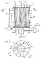
- the evaporator of FIG. 1 comprises a cylindrical heating body 1 inside which a tubular bundle 2 is disposed vertically, the upper and lower tubular plates of which are shown respectively in 3 and 4.
- a series of beam tubes for the simplicity of the drawing, there is no represented that a series of beam tubes
- tubular plate 3 Above the tubular plate 3 is formed a cylindrical supply chamber 5 and below the tubular plate 4 is arranged a cylindrical extraction chamber 6.
- the supply chamber 5 is divided by two vertical and parallel partitions 7, 8 into three compartments 9, 10, 11 into which three inlets of concentrated liquid product 12, 13, 14 penetrate respectively.
- the heating body 1 is divided into three compartments 15, 16, 17 by two vertical and parallel partitions 18, 19 located respectively in the same plane as the partitions 7, 8.
- the extraction chamber 6 is also divided into three compartments 20, 21, 22 by two vertical and parallel partitions 23, 24 located in the same plane as the partitions 18, 19.
- each of the compartments 15, 16, 17 may possibly differ from one compartment to another depending on the requirements of the treatment.
- the compartments 20, 21 are connected by their base respectively to the extraction pumps 25, 26 whose outlets are connected respectively to the inlets 13, 14.
- the extraction compartments 20, 21, 22 are connected by steam pipes 28, 29, 30 respectively to steam-liquid separators 31, 32, 33 which carry steam pipes 34 at their upper part, 35, 36, the pipes 34, 35 opening respectively into the compartments 16, 17 and the pipe 36 being connected to a condenser (not shown).
- compartment 15 As for compartment 15; it carries a steam supply 37.
- the overall operation of the evaporator thus formed is identical to that of a conventional triple-effect evaporator whose first effect would be constituted by compartments 9, 15, 20, whose second effect would be constituted by compartments 10, 16 , 21 and the third effect would be constituted by compartments 11, 17, 20.
- the product to be concentrated is introduced via the inlet 12 into the compartment 9 and it is distributed in the fraction of the tubular bundle contained in the compartment 15, by any distribution means (not shown), for example that described in the French patent. No. 1 226 700. After having passed through the tubes of this fraction and thereby undergoing a first concentration, the liquid product reaches compartment 20 from where it is taken up by pump 25 and led by inlet 13 into the compartment 10. The product is then distributed by a distribution means (not shown) in the tubular fraction contained in compartment 16 where it undergoes a greater concentration before reaching compartment 21.
- the vapor created by the evaporation of the product in the fraction of the tubular bundle contained in the compartment 15 is directed via the compartment 20, the pipes 28 and 34 and the separator 31, towards the compartment 16 where it will serve as a source. calories.
- the vapor created by the evaporation of the product in the fraction of the tubular bundle contained in compartment 16 is directed via compartment 21, the pipes 29 and 35 and the separator 32 towards compartment 17 where it will serve as source of calories.
- the steam which transfers its calories to the product to be condensed condenses in the compartments 15, 16 and 17, the condensates being withdrawn from the latter as and when they function, in known manner by extraction means such as a pump (not shown).
- the partitions 7, 8, 18, 19, 23, 24 can be constituted by simple sheets welded on the tubular plates 3, 4, on the bottom of the extraction chamber 6, on the cover of the supply chamber 5 and the side walls of these chambers 5, 6 and of the body 1, these sheets not requiring any particular qualities of resistance to pressure since the pressure prevailing in compartment 15 is generally not too different from that prevailing in compartment 16 and the pressure prevailing in the latter is usually not too different from that prevailing in compartment 17.
- FIG. 2 corresponds to that presented by the compartments of the evaporator according to FIG. 1.
- FIG. 3 shows compartments in the form of sectors 38, 39, 40, the referenced partitions 41, 42, 43 being in this vertical eye and connected by one of their vertical edges.
- FIG. 6 represents an evaporator with two concentric effects.
- This evaporator has the same elements 1 to 5 as the evaporator of FIG. 1.
- the supply chamber 5 is however divided by a vertical partition 55 of cylindrical shape, into a central cylindrical compartment 56 and an annular compartment 57 disposed concentrated around compartment 56, compartments into which two inlets of product to be concentrated respectively 58.59.
- the heating body 1 is divided into two concertric cylindrical compartments 60, 61 by a cylindrical partition 62 fixed on the upper tubular plate 3, arranged in the extension of the partition 55 and whose lower edge is located at a small distance from the lower tubular plate 4.
- the base of this partitioning 62 cooperates with means ensuring the seal between the compartments 60, 61.
- These means consist of a vertical wall 63 defining a cylinder which s 'fits into the compartment 60 so that said wall 63 and said partition 62 partially overlap.
- the distance between the lower edge of the partition 62 and the upper edge of the wall 63 respectively of the lower tubular plate 4 and of the upper tubular plate 3 is chosen on the one hand, so that said edges cannot be supported.
- the wall 63 can be produced in such a way that it is the cylinder defined by the partition 62 which fits into the cylinder defined by the wall 63 ..
- a cylindrical extraction chamber 65 is provided under the lower tabular plate 4, this chamber consisting of two independent concentric cylindrical compartments 66, 67, the central compartment 67 being higher than the other compartment 66, so that it can easily connect this compartment to a steam pipe 68 opening into a vapor-liquid separator 69, without this tubing passing through the compartment 66.
- the upper part of the separator 69 is for its part connected by a conduit 70 to a condenser.
- a steam pipe 71 connects the compartment 66 to a vapor-liquid separator 72, the upper part of which carries a steam pipe 73 opening into the compartment 60.
- the compartments 66, 67 are connected by their base respectively at the suction of the extraction pumps 74, 75, the discharge of the pump 74 being connected to the inlet 58.
- the compartment 61 is provided with a steam inlet 76 and the side wall of the heating body 1 is provided with a cylindrical expansion bellows 77.
- the compartments 56 and 57 contain distribution means capable of distributing the product to be concentrated in the fractions of tubes contained respectively in compartments 60, 61.
- the evaporators which have just been described are of the trickle type, but the invention naturally extends to evaporators of the gritpage type.
- the steam pipe 73 instead of passing through the compartment 61 could enter the compartment 60 by passing through the compartment 67 and the lower tube plate 4.
- the evaporators according to the invention could be mechanically recompressed by steam or steam thermocompression, in which case, and if we consider for example the evaporator according to FIG. 6, the pipe 73 would carry a bypass connected to the suction of a mechanical compressor or of a steam thermocompressor, whose discharge would be connected to the steam supply 76.
Landscapes
- Chemical & Material Sciences (AREA)
- Chemical Kinetics & Catalysis (AREA)
- Vaporization, Distillation, Condensation, Sublimation, And Cold Traps (AREA)
- Dairy Products (AREA)
Applications Claiming Priority (2)
| Application Number | Priority Date | Filing Date | Title |
|---|---|---|---|
| FR8212668 | 1982-07-20 | ||
| FR8212668A FR2530480B1 (fr) | 1982-07-20 | 1982-07-20 | Perfectionnement aux evaporateurs du type a multiple effet |
Publications (1)
| Publication Number | Publication Date |
|---|---|
| EP0100263A1 true EP0100263A1 (de) | 1984-02-08 |
Family
ID=9276134
Family Applications (1)
| Application Number | Title | Priority Date | Filing Date |
|---|---|---|---|
| EP83401426A Withdrawn EP0100263A1 (de) | 1982-07-20 | 1983-07-11 | Mehrstufige Verdampfer |
Country Status (3)
| Country | Link |
|---|---|
| EP (1) | EP0100263A1 (de) |
| ES (1) | ES524235A0 (de) |
| FR (1) | FR2530480B1 (de) |
Cited By (7)
| Publication number | Priority date | Publication date | Assignee | Title |
|---|---|---|---|---|
| FR2564330A1 (fr) * | 1984-05-16 | 1985-11-22 | Laguilharre Sa | Perfectionnement aux evaporateurs a flot tombant et a circulation forcee |
| FR2583651A1 (fr) * | 1985-06-21 | 1986-12-26 | Laguilharre Sa | Evaporateur monocorps pour la concentration d'au moins un produit liquide, comportant au moins deux sections d'evaporation et installation d'evaporation comprenant un tel evaporateur |
| FR2584939A1 (fr) * | 1985-07-16 | 1987-01-23 | Laguilharre Sa | Procede et installation pour l'evaporation d'un produit liquide, notamment un produit liquide incrustant |
| EP0862935B1 (de) * | 1997-01-10 | 2003-06-04 | France EVAPORATION | Vorrichtung zur Trennung von einem Gas aus einer Flüssigkeit und Anlage mit einer solchen Vorrichtung |
| WO2006029798A1 (de) * | 2004-09-17 | 2006-03-23 | Uhde Gmbh | Teillastfähiger fallfilmverdampfer und verfahren zum teillastbetrieb |
| EP2837533A1 (de) | 2013-08-15 | 2015-02-18 | Meritor Heavy Vehicle Braking Systems (UK) Limited | Verfahren zum Einstellen einer Bremse |
| EP2998606A1 (de) | 2014-09-18 | 2016-03-23 | Meritor Heavy Vehicle Braking Systems (UK) Limited | Verfahren zur Betätigung einer Bremse |
Families Citing this family (1)
| Publication number | Priority date | Publication date | Assignee | Title |
|---|---|---|---|---|
| DK180765B1 (en) * | 2018-08-20 | 2022-03-01 | Spx Flow Tech Danmark A/S Udviklingsafdeling | Falling film tubular evaporator |
Citations (10)
| Publication number | Priority date | Publication date | Assignee | Title |
|---|---|---|---|---|
| GB191028925A (en) * | 1910-12-13 | 1911-12-13 | Joseph Simon Studer | Improvements in Evaporating Apparatus. |
| GB180963A (en) * | 1920-12-24 | 1922-05-24 | Thomas Rigby | Improvements in or relating to distilling, concentrating or drying apparatus |
| FR562476A (fr) * | 1922-12-29 | 1923-11-12 | évaporateur à circulation | |
| DE441497C (de) * | 1924-04-06 | 1927-03-08 | Fraembs & Freudenberg | Stehender Umlaufverdampfer |
| DE456193C (de) * | 1926-01-16 | 1928-02-17 | Ermin Pokorny | Umlaufverdampfer |
| DE1066541B (de) * | 1957-11-26 | 1959-10-08 | Patentauswertung Vogelbusch Ge | Verdampfer mit mehrteiligem Fluessigkeitsraum |
| GB1040224A (en) * | 1965-06-11 | 1966-08-24 | Patrick Murray Proprietary Ltd | Improvements relating to vacuum pans and similar apparatus |
| DE2015235A1 (de) * | 1969-04-08 | 1970-10-22 | ||
| DE2311350A1 (de) * | 1972-04-21 | 1973-11-08 | Rudisleben Chemieanlagenbau | Mehrkammerumlaufverdampfer |
| GB1530489A (en) * | 1971-03-05 | 1978-11-01 | Bp Chem Int Ltd | Process for the removal of mercury from aqueous solutions |
-
1982
- 1982-07-20 FR FR8212668A patent/FR2530480B1/fr not_active Expired
-
1983
- 1983-07-11 EP EP83401426A patent/EP0100263A1/de not_active Withdrawn
- 1983-07-19 ES ES524235A patent/ES524235A0/es active Granted
Patent Citations (10)
| Publication number | Priority date | Publication date | Assignee | Title |
|---|---|---|---|---|
| GB191028925A (en) * | 1910-12-13 | 1911-12-13 | Joseph Simon Studer | Improvements in Evaporating Apparatus. |
| GB180963A (en) * | 1920-12-24 | 1922-05-24 | Thomas Rigby | Improvements in or relating to distilling, concentrating or drying apparatus |
| FR562476A (fr) * | 1922-12-29 | 1923-11-12 | évaporateur à circulation | |
| DE441497C (de) * | 1924-04-06 | 1927-03-08 | Fraembs & Freudenberg | Stehender Umlaufverdampfer |
| DE456193C (de) * | 1926-01-16 | 1928-02-17 | Ermin Pokorny | Umlaufverdampfer |
| DE1066541B (de) * | 1957-11-26 | 1959-10-08 | Patentauswertung Vogelbusch Ge | Verdampfer mit mehrteiligem Fluessigkeitsraum |
| GB1040224A (en) * | 1965-06-11 | 1966-08-24 | Patrick Murray Proprietary Ltd | Improvements relating to vacuum pans and similar apparatus |
| DE2015235A1 (de) * | 1969-04-08 | 1970-10-22 | ||
| GB1530489A (en) * | 1971-03-05 | 1978-11-01 | Bp Chem Int Ltd | Process for the removal of mercury from aqueous solutions |
| DE2311350A1 (de) * | 1972-04-21 | 1973-11-08 | Rudisleben Chemieanlagenbau | Mehrkammerumlaufverdampfer |
Cited By (9)
| Publication number | Priority date | Publication date | Assignee | Title |
|---|---|---|---|---|
| FR2564330A1 (fr) * | 1984-05-16 | 1985-11-22 | Laguilharre Sa | Perfectionnement aux evaporateurs a flot tombant et a circulation forcee |
| FR2583651A1 (fr) * | 1985-06-21 | 1986-12-26 | Laguilharre Sa | Evaporateur monocorps pour la concentration d'au moins un produit liquide, comportant au moins deux sections d'evaporation et installation d'evaporation comprenant un tel evaporateur |
| FR2584939A1 (fr) * | 1985-07-16 | 1987-01-23 | Laguilharre Sa | Procede et installation pour l'evaporation d'un produit liquide, notamment un produit liquide incrustant |
| EP0862935B1 (de) * | 1997-01-10 | 2003-06-04 | France EVAPORATION | Vorrichtung zur Trennung von einem Gas aus einer Flüssigkeit und Anlage mit einer solchen Vorrichtung |
| WO2006029798A1 (de) * | 2004-09-17 | 2006-03-23 | Uhde Gmbh | Teillastfähiger fallfilmverdampfer und verfahren zum teillastbetrieb |
| US7959768B2 (en) | 2004-09-17 | 2011-06-14 | Uhde Gmbh | Partial load enabled falling film evaporator and method for operating a partial load |
| EP2837533A1 (de) | 2013-08-15 | 2015-02-18 | Meritor Heavy Vehicle Braking Systems (UK) Limited | Verfahren zum Einstellen einer Bremse |
| EP3540257A1 (de) | 2013-08-15 | 2019-09-18 | Meritor Heavy Vehicle Braking Systems (UK) Limited | Verfahren zum einstellen einer bremse |
| EP2998606A1 (de) | 2014-09-18 | 2016-03-23 | Meritor Heavy Vehicle Braking Systems (UK) Limited | Verfahren zur Betätigung einer Bremse |
Also Published As
| Publication number | Publication date |
|---|---|
| FR2530480B1 (fr) | 1988-07-29 |
| FR2530480A1 (fr) | 1984-01-27 |
| ES8403733A1 (es) | 1984-04-16 |
| ES524235A0 (es) | 1984-04-16 |
Similar Documents
| Publication | Publication Date | Title |
|---|---|---|
| EP0100263A1 (de) | Mehrstufige Verdampfer | |
| FR2540739A1 (fr) | Dispositif et installations pour la distillation par evaporation en couches minces, en particulier pour hydrocarbures, et procede de mise en oeuvre de ce dispositif | |
| EP0665042A2 (de) | Luftdistillationskolonne mit einer Well cross Packung | |
| FR2655877A1 (fr) | Distributeur de fluides pour colonne d'echange de chaleur et de matiere, notamment a garnissage, et colonne munie d'un tel distributeur. | |
| FR2463801A1 (fr) | Dispositif pour le traitement de gaz de synthese obtenu par la gazeification de charbon | |
| EP0068958B1 (de) | Dampferzeuger mit einem dynamischen Dampfwasserableiter | |
| FR2929858A1 (fr) | Filtre a carburant et cartouche filtrante permettant un degazage | |
| FR2774755A1 (fr) | Condenseur a plaques brasees perfectionne et son application aux doubles colonnes de distillation d'air | |
| FR2594045A1 (fr) | Filtre auto-nettoyant, et boite a eau d'entree de condenseur de vapeur comportant un tel filtre. | |
| EP0527679A1 (de) | Traubenentsafter und Verfahren zum Entsaften von Traubenverwendung diesem Entsafter | |
| EP0032088B1 (de) | Vorrichtung zum Trennen von Flüssigkeit und Dampf aus einem Fluid-Strom und Dampferzeuger mit solchen Vorrichtungen | |
| EP0718583B1 (de) | Vorrichtung zur Zirkulation eines Fluids | |
| EP0060163B1 (de) | Vorrichtung zur Behandlung von textilen Materialien durch die Wirkung von Flüssigkeiten oder Gasen | |
| CA1118651A (fr) | Separateur-surchauffeur vertical de vapeur | |
| EP3105520B1 (de) | Säule zur trennung von luft durch kryogene destillation, lufttrennungsvorrichtung mit solch einer säule und verfahren zur herstellung solch einer säule | |
| FR2564330A1 (fr) | Perfectionnement aux evaporateurs a flot tombant et a circulation forcee | |
| FR2651645A1 (fr) | Dispositif pour l'amelioration de la qualite de la vendange par maturation ou surmaturation, en vue de la vinification. | |
| LU81954A1 (fr) | Appareil pour le dessalement de l'eau de mer | |
| BE879140R (fr) | Separateur-surchauffeur de vapeur vertical | |
| FR2676371A1 (fr) | Colonne de distillation d'air a garnissage ondule-croise. | |
| EP4388067A1 (de) | Vorrichtung und verfahren zur extraktion von pflanzenflüssigkeit | |
| FR2583651A1 (fr) | Evaporateur monocorps pour la concentration d'au moins un produit liquide, comportant au moins deux sections d'evaporation et installation d'evaporation comprenant un tel evaporateur | |
| BE445870A (fr) | Appareil pour la distillation et la concentration des liquides par utilisation de la chaleur restituée par les vapeurs qui se condensent | |
| FR2507580A1 (fr) | Citerne pour suspensions | |
| EP0415819B1 (de) | Metalldeckel für gasdichte Behälter |
Legal Events
| Date | Code | Title | Description |
|---|---|---|---|
| PUAI | Public reference made under article 153(3) epc to a published international application that has entered the european phase |
Free format text: ORIGINAL CODE: 0009012 |
|
| AK | Designated contracting states |
Designated state(s): AT BE CH DE GB IT LI LU NL SE |
|
| 17P | Request for examination filed |
Effective date: 19840719 |
|
| STAA | Information on the status of an ep patent application or granted ep patent |
Free format text: STATUS: THE APPLICATION HAS BEEN WITHDRAWN |
|
| 18W | Application withdrawn |
Withdrawal date: 19871211 |
|
| RIN1 | Information on inventor provided before grant (corrected) |
Inventor name: CIBOIT, JACQUES JEAN |