EP0100449A1 - Fauteuil roulant pour invalides - Google Patents
Fauteuil roulant pour invalides Download PDFInfo
- Publication number
- EP0100449A1 EP0100449A1 EP83106471A EP83106471A EP0100449A1 EP 0100449 A1 EP0100449 A1 EP 0100449A1 EP 83106471 A EP83106471 A EP 83106471A EP 83106471 A EP83106471 A EP 83106471A EP 0100449 A1 EP0100449 A1 EP 0100449A1
- Authority
- EP
- European Patent Office
- Prior art keywords
- cylinder
- seat
- wheelchair
- piston
- articulated
- Prior art date
- Legal status (The legal status is an assumption and is not a legal conclusion. Google has not performed a legal analysis and makes no representation as to the accuracy of the status listed.)
- Ceased
Links
- 230000006641 stabilisation Effects 0.000 claims abstract description 4
- 238000011105 stabilization Methods 0.000 claims abstract description 4
- 239000000725 suspension Substances 0.000 claims description 3
- 230000000087 stabilizing effect Effects 0.000 claims description 2
- 230000009194 climbing Effects 0.000 abstract description 2
- 230000008719 thickening Effects 0.000 description 3
- 0 CCC(C1)C(C2)(C2(*)C2)C2([*+]C)*1IC Chemical compound CCC(C1)C(C2)(C2(*)C2)C2([*+]C)*1IC 0.000 description 2
- 230000001960 triggered effect Effects 0.000 description 2
- 241001295925 Gegenes Species 0.000 description 1
- 238000010276 construction Methods 0.000 description 1
- 230000001276 controlling effect Effects 0.000 description 1
- 238000006073 displacement reaction Methods 0.000 description 1
- 238000000034 method Methods 0.000 description 1
- 230000001105 regulatory effect Effects 0.000 description 1
Images

Classifications
-
- A—HUMAN NECESSITIES
- A61—MEDICAL OR VETERINARY SCIENCE; HYGIENE
- A61G—TRANSPORT, PERSONAL CONVEYANCES, OR ACCOMMODATION SPECIALLY ADAPTED FOR PATIENTS OR DISABLED PERSONS; OPERATING TABLES OR CHAIRS; CHAIRS FOR DENTISTRY; FUNERAL DEVICES
- A61G5/00—Chairs or personal conveyances specially adapted for patients or disabled persons, e.g. wheelchairs
- A61G5/06—Chairs or personal conveyances specially adapted for patients or disabled persons, e.g. wheelchairs with obstacle mounting facilities, e.g. for climbing stairs, kerbs or steps
- A61G5/061—Chairs or personal conveyances specially adapted for patients or disabled persons, e.g. wheelchairs with obstacle mounting facilities, e.g. for climbing stairs, kerbs or steps for climbing stairs
-
- A—HUMAN NECESSITIES
- A61—MEDICAL OR VETERINARY SCIENCE; HYGIENE
- A61G—TRANSPORT, PERSONAL CONVEYANCES, OR ACCOMMODATION SPECIALLY ADAPTED FOR PATIENTS OR DISABLED PERSONS; OPERATING TABLES OR CHAIRS; CHAIRS FOR DENTISTRY; FUNERAL DEVICES
- A61G5/00—Chairs or personal conveyances specially adapted for patients or disabled persons, e.g. wheelchairs
- A61G5/06—Chairs or personal conveyances specially adapted for patients or disabled persons, e.g. wheelchairs with obstacle mounting facilities, e.g. for climbing stairs, kerbs or steps
- A61G5/068—Chairs or personal conveyances specially adapted for patients or disabled persons, e.g. wheelchairs with obstacle mounting facilities, e.g. for climbing stairs, kerbs or steps with extensible supports pushing upwards, e.g. telescopic legs
-
- Y—GENERAL TAGGING OF NEW TECHNOLOGICAL DEVELOPMENTS; GENERAL TAGGING OF CROSS-SECTIONAL TECHNOLOGIES SPANNING OVER SEVERAL SECTIONS OF THE IPC; TECHNICAL SUBJECTS COVERED BY FORMER USPC CROSS-REFERENCE ART COLLECTIONS [XRACs] AND DIGESTS
- Y10—TECHNICAL SUBJECTS COVERED BY FORMER USPC
- Y10S—TECHNICAL SUBJECTS COVERED BY FORMER USPC CROSS-REFERENCE ART COLLECTIONS [XRACs] AND DIGESTS
- Y10S280/00—Land vehicles
- Y10S280/10—Stair climbing chairs
Definitions
- the invention relates to a wheelchair for the disabled, the suspension of a pair of wheels can be adjusted in a vertical direction relative to the chassis by a piston-cylinder arrangement, with a seat articulated on a chassis so that the seat is in its horizontal position at different inclinations of the chassis can maintain and with a central control unit for pneumatic control both the adjustment of the wheel bearings and the adjustment of the seat.
- the invention has for its object to design a wheelchair for the disabled so that the disabled in the wheelchair is basically able to go up or down stairs with this wheelchair without the help of another person, with an auxiliary or accompanying person without Perhaps only the task should be to exercise a safety function against psychologically crossing the individual steps too quickly for psychological reasons.
- the wheelchair according to the invention is characterized in that the chassis has two frames lying one above the other at a distance in parallel, on the lateral longitudinal spars for the vertical adjustment of eight wheelchair wheels combined into four wheel groups, vertical piston-cylinder units are articulated in such a way that the frame with the piston-cylinder units in the lateral projection are adjustable in the manner of a parallelogram linkage, with pneumatic cylinders being articulated between the longitudinal bars to stabilize or fixing the relative positions between the upper and lower frames, and that the wheelchair wheels are driven by motors powered by a battery pack .
- the wheelchair is assigned safety, regulating and control devices as described in the subclaims.
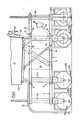
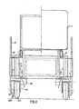
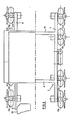
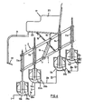
- the drawings show in different views a schematically represented wheelchair for the disabled.
- the frame of this wheelchair consists of two superimposed frames 1 and 2, in particular of square tube.
- the lower frame 1 consists of two longitudinal spars 3 and 4 running parallel to the direction of travel of the wheelchair and two parallel transverse spars 5 and 6, which are fastened to the latter to form a central rectangular frame part at a distance from the ends of the longitudinal spars 3 and 4.
- the upper frame 2 preferably has the same shape as the lower frame, i. H. the upper frame consists of two parallel longitudinal bars 7 and 8, which are connected by cross bars 9 and 10.
- the shape of the upper frame 2 and thus also the shape of the lower frame result in particular from FIG. 3.
- the cylinders 11a to 11h and the corresponding piston-cylinder units are used for vertical adjustment of pneumatic tires 12a to 12h, the storage of which is described below.
- Pneumatic cylinders 13 and 14 are articulated between the longitudinal spars 3 and 7 on the one hand and 4 and 8 on the other, which serve to stabilize or fix the relative position between the upper and lower frames.
- a seat 17 is pivotally mounted on the upper frame 2 by means of two bearing blocks 15, 16 fastened to the longitudinal bars 7 and 8 respectively.
- To stabilize the seat 17 are arranged on both long sides of the frame handlebars 18 and 19, which are articulated on the one hand on the longitudinal bars 3, 4 of the lower frame 1 and on the other hand on the underside of the seat 17.
- the length of the handlebars 18, 19 and the position of the upper and lower pivot points are coordinated so that regardless of the position of the two frames 1 and 2, the same relative position of the seat is always guaranteed relative to a horizontal reference plane, as can be seen from the Figures 1 and 4 results.
- Other devices preferably in the form of pneumatic cylinders, can also be provided for stabilizing the seat in its horizontal position.
- the seat 17 consists essentially of a square tube frame 20, to which 21 footrests 22 are attached via a linkage, and a seat shell 23.
- a travel switch (not shown) and a steering device (also not shown) are mounted on the seat 17.
- Basic further components of the wheelchair according to the invention are a battery pack 24 which is rotatably attached to the upper frame 2, a compressed air container 25 rigidly mounted on the lower frame 1 with an associated compressor 26 and a steering system (not shown in detail) for controlling the turning of the individual wheel groups.
- One on the rear of the seat 17 attached level control device 27 with an associated control device is used to maintain the predetermined relative position of the seat 17 relative to the horizontal reference plane and to control the application of compressed air to the individual cylinder units 11a to 11h and 13, 14.
- the wheels are assigned horizontally movable contact brackets 28a to 28h which, on the one hand, have lower ground contacts 29a to 29h and, on the other hand, can actuate side contacts (not shown) by horizontal displacement.
- An electric drive motor 30a to 30h is assigned to each wheel 12a to 12h.
- the drive motors are connected to the battery pack 24 by means of lines, not shown.
- the sequence of functions for driving the wheelchair according to the invention up the stairs is as follows: the drive motors 30a to 30h drive the wheels 12a to 12h backwards at low speed.
- the contact brackets 29d, 29h of the rear pair of wheels 12d, 12h hit the first kick I and are adjusted in the horizontal direction and thereby actuate the side contacts
- microprocessors of all wheel sets integrated in the level control device and the control unit 27 are activated, on the one hand all drive motors 30a to 30h and on the other hand, with the exception of the cylinders 11d, 11h, to pressurize all other cylinders 11a to 11e in such a way that the associated pistons and thus the wheels 12a to 12g are extended downwards, as a result of which the wheelset comprising the wheels 12d and 12h raised together with frames 1 and 2 until the assigned contact brackets 28d and 28h are relieved, ie no longer abut the kick I.
- an locking system is provided in order to lock all cylinders 11a to 11h and the pneumatic cylinders 13 and 14 in the respective position.
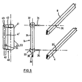
- FIGS 5 and 6 show in an exploded view the mounting or suspension of the individual wheels including the piston-cylinder units articulated on the longitudinal spars.
- the individual piston-cylinder unit 11 consists of a cylinder 31 which is provided with radially projecting thickenings 32 and 33 at its upper and lower ends is. At these thickened portions 32 and 33, stub axles 34 and 35 are fastened, which can preferably be hollow, in order to connect the upper and lower ends of the cylinder 31 to the compressed air container 25 by means of compressed air lines, not shown in detail.
- the two longitudinal spars 8 and 4 are provided with bearing bores 36 for receiving the stub axles 34 and 35, respectively.
- the piston rod 38 protruding from the cylinder 31 has a threaded section 39 at its lower end.
- a parallel guide element 40 is pushed onto the cylinder 31 between the radial thickenings 32 and 33.
- at least one of the two thickenings 32 or 33 is detachably attached to the cylinder 31.
- the parallel guide element 4o consists of a first pipe section 41 encompassing the cylinder 31, which is rigidly connected by means of a web 41 ′ and lower and upper trapezoidal stiffening plates 42 to a second pipe section 43 running parallel to the first pipe section 41.
- a steering bracket 53 is attached laterally.
- the second pipe section 43 serves for axially displaceable mounting of the parallel guide pipe 44 shown in FIG. 6, which is secured against rotation relative to the second pipe section 43.
- a cross bracket 45 is attached, to which a bearing cheek 46 is attached, which in turn runs parallel to the parallel guide tube 44.
- the crossbar 45 is provided with an upwardly open threaded bore 52 into which the threaded portion 39 of the piston rod 38 is screwed.
- both the parallel guide tube 44 and the bearing cheek 46 there are bearing bushes 47 and 48 for receiving the axle of a wheel 12.
- the cheek 46 is provided with a further bearing bore 49 for fastening the drive motor 3o, which is not described in detail Common gear elements shown are used to drive the wheel 12.
- a contact box 50 is preferably fastened in the area of the bearing bush 47, which serves with horizontally lying guide bores 51 for a contact bracket 28, which carries the bottom contact 29 already described above on its underside.
- the contact bracket 28 can be displaced in the horizontal direction against an elastic biasing force relative to the contact box 5o, in order to be able to actuate the side contacts arranged within the contact box 5o in the manner already described above.
- the piston rod 38 When compressed air is applied to the piston-cylinder unit 11, the piston rod 38 is either retracted or extended, as a result of which a correspondingly directed force is transmitted to the crossbar attached to the parallel guide tube 44.
- the parallel guide tube 44 is adjusted in the vertical direction within the second tube section 43, and thus also the wheel 12 mounted between the lower end of the parallel guide tube 44 and the bearing cheek 46.
- a pressure switch 54 is assigned to the second pipe section 43 and thus to the parallel guide pipe 44 (see FIGS. 2, 5 and 7).
- the pressure switch 54 fastened laterally in the region of a wall opening of the second pipe section 43 consists of a cylinder housing 55 in which a plunger 56 is slidably mounted.
- This plunger 56 is loaded on one side via a pressure plate 57 by a spring 58, which exerts a force on the plunger 56 in such a direction that a pressure ram 59 arranged on the other plunger cables is displaceable in an opening 61 of a cylinder cover 60 is stored, is extended so far from the cylinder that it is pressed through the above-mentioned wall opening of the second pipe section 43 into the locking and locking position against the parallel guide pipe 44.
- a compressed air line 62 which is also connected to the compressed air container 25, opens into the cylinder space of the cylinder 55 facing the cylinder cover 6o.
- compressed air supply to the plunger 56 of the associated pressure switch 54 is also required in order to move the pressure plunger 59 against the force of the spring 58 from the position inserted into the second pipe section 43 and locking the parallel guide pipe 44 can.
- the parallel guide tube 44 has reached an end position again, the compressed air supply to the plunger 56 is interrupted, so that the pressure ram 59 is then moved back into its position locking the parallel guide tube under the influence of the force of the spring 58.
- the pressure switch 54 thus fulfills the purpose of preventing uncontrolled vertical adjustments of the individual wheels in the event of faults in the compressed air system.
- a steering system or steering linkage engages in a manner not belonging to the invention individual steering straps 53 of the parallel guide elements 4o.
- the individual parallel guide element 40 is rotated with its first tube section 41 around the axis of the cylinder 11, which results in a corresponding pivoting movement of the second tube section 43.
- This pivoting movement is followed by the parallel guide tube 44 secured against rotation within the second tube section, which results in a corresponding change in the running or steering position of the individual wheel 12.
Landscapes
- Health & Medical Sciences (AREA)
- Life Sciences & Earth Sciences (AREA)
- Animal Behavior & Ethology (AREA)
- General Health & Medical Sciences (AREA)
- Public Health (AREA)
- Veterinary Medicine (AREA)
- Handcart (AREA)
Applications Claiming Priority (2)
| Application Number | Priority Date | Filing Date | Title |
|---|---|---|---|
| DE3225354A DE3225354C2 (de) | 1982-07-07 | 1982-07-07 | Rollstuhl für Behinderte |
| DE3225354 | 1982-07-07 |
Publications (1)
| Publication Number | Publication Date |
|---|---|
| EP0100449A1 true EP0100449A1 (fr) | 1984-02-15 |
Family
ID=6167830
Family Applications (1)
| Application Number | Title | Priority Date | Filing Date |
|---|---|---|---|
| EP83106471A Ceased EP0100449A1 (fr) | 1982-07-07 | 1983-07-02 | Fauteuil roulant pour invalides |
Country Status (5)
| Country | Link |
|---|---|
| US (1) | US4569409A (fr) |
| EP (1) | EP0100449A1 (fr) |
| JP (1) | JPS5964045A (fr) |
| DE (1) | DE3225354C2 (fr) |
| ES (1) | ES523946A0 (fr) |
Cited By (6)
| Publication number | Priority date | Publication date | Assignee | Title |
|---|---|---|---|---|
| GB2201926A (en) * | 1987-03-04 | 1988-09-14 | Monticolombi C G R | Improvements in or relating to a stair-climbing device |
| EP0156807B1 (fr) * | 1983-09-09 | 1991-02-06 | HESTER, Robert | Vehicule et son procede de fonctionnement |
| GB2325903A (en) * | 1997-06-06 | 1998-12-09 | Robert George Hester | Kerb mounting wheeled conveyance |
| WO2001053137A1 (fr) * | 2000-01-17 | 2001-07-26 | Elsteel Danmark A/S | Dispositif de transport et procede permettant de commande un dispositif de transport |
| CN109363844A (zh) * | 2018-12-13 | 2019-02-22 | 西安交通大学 | 一种障碍跨越控制装置及控制方法 |
| EP3679912A2 (fr) | 2019-01-09 | 2020-07-15 | Ammann, Gerda | Fauteuil roulant permettant de surmonter les obstacles |
Families Citing this family (39)
| Publication number | Priority date | Publication date | Assignee | Title |
|---|---|---|---|---|
| JPS62117558A (ja) * | 1985-11-18 | 1987-05-29 | 東邦機工株式会社 | 階段の昇降自在な車椅子装置 |
| IL98207A (en) * | 1991-05-22 | 1994-08-26 | Israel Aircraft Ind Ltd | Wheelchair with apparatus for assisting travel on a surface not suitable for wheeled travel |
| US5507358A (en) * | 1993-06-04 | 1996-04-16 | Kabushiki Kaisha Daikin Seisakusho | Stair climbing vehicle |
| US5562172A (en) * | 1994-01-06 | 1996-10-08 | Mick; Jeffrey | Wheeled vehicle arrangement for distributing agricultural materials in fields having undulations such as soft walled levees and the like |
| US6003624A (en) * | 1995-06-06 | 1999-12-21 | University Of Washington | Stabilizing wheeled passenger carrier capable of traversing stairs |
| JPH09309469A (ja) * | 1996-05-23 | 1997-12-02 | Exedy Corp | 階段昇降車 |
| US6276704B1 (en) * | 1997-09-23 | 2001-08-21 | Charles J. Suiter | Adjustable wheelchair having a tilting and reclining seat |
| GB2346852B (en) | 1998-07-31 | 2001-06-13 | Ferno Washington | Chairs |
| DE19955199C1 (de) * | 1999-11-16 | 2001-06-13 | Karlsruhe Forschzent | Treppensteigendes Fahrzeug |
| US6695084B2 (en) * | 2001-02-22 | 2004-02-24 | Peter J. Wilk | Personal hovercraft with stairway climbing |
| CN1582873B (zh) * | 2003-08-22 | 2010-04-28 | 贾荣显 | 气动助力可上下楼梯的轮椅车 |
| US7246671B2 (en) * | 2005-01-10 | 2007-07-24 | Michael Goren | Stair-climbing human transporter |
| WO2007079346A2 (fr) * | 2005-12-30 | 2007-07-12 | Olsen Christopher J | Ensembles roue articulée et véhicules qui en sont équipés |
| TW200843992A (en) * | 2007-05-02 | 2008-11-16 | Univ Nat Chiao Tung | Carrier with barrier-overpassing |
| TW200844406A (en) * | 2007-05-02 | 2008-11-16 | Univ Nat Chiao Tung | Sensing apparatus |
| RU2347706C1 (ru) * | 2007-08-20 | 2009-02-27 | Дмитрий Александрович Иосселиани | Тележка хозяйственная повышенной проходимости |
| DE102009052215A1 (de) | 2009-11-06 | 2011-05-12 | Medvetskiy, Oleksandr | Der Handzweiradkarren oder der Koffer mit der Einrichtung für die Überwindung der engen und tiefen Hindernisse |
| DE202010001115U1 (de) | 2010-01-20 | 2010-06-17 | Medvetskiy, Oleksandr | Der Handzweiradkarren oder der Koffer mit der Einrichtung für die Überwindung der engen und tiefen Hindernisse |
| US8418787B2 (en) | 2011-01-10 | 2013-04-16 | King Fahd University Of Petroleum And Minerals | Stair climbing apparatus |
| CN102730097A (zh) * | 2011-04-14 | 2012-10-17 | 牛晓蓉 | 多用机动楼梯台阶车 |
| CN102319153B (zh) * | 2011-06-23 | 2014-03-26 | 耿冬 | 手动爬楼车 |
| ES2417979B1 (es) * | 2011-09-24 | 2014-10-30 | Bayron Sicilia Acosta | Mecanismo con Brazo-Rampa Para Subir y Bajar Escaleras |
| US8764027B1 (en) | 2013-01-28 | 2014-07-01 | Michael Della Polla | Slab dolly |
| CN104207899B (zh) * | 2014-03-27 | 2016-08-24 | 刘继伦 | 爬楼梯轮椅 |
| CN104546327A (zh) * | 2015-01-20 | 2015-04-29 | 王宝金 | 一种折叠型平移式电动爬楼轮椅 |
| US9937968B2 (en) | 2015-07-13 | 2018-04-10 | Michael Goren | Stackable vehicle |
| US10202141B2 (en) * | 2015-07-13 | 2019-02-12 | Hurdler Motors | Vehicle, vehicle drive assembly and vehicle steering assembly |
| CA2999862C (fr) | 2015-09-25 | 2025-05-20 | The United States Government As Represented By The Department Of Veterans Affairs | Fauteuil roulant améliorant la mobilité |
| DE102015012755A1 (de) | 2015-10-01 | 2017-04-06 | Andreas Wulff | Laufstuhl |
| DE202015006899U1 (de) | 2015-10-01 | 2016-02-12 | Andreas Wulff | Laufstuhl |
| MX2018006147A (es) * | 2015-11-23 | 2018-09-17 | Quantum Robotic Systems Inc | Dispositivo para cruzar escaleras. |
| JP6055981B1 (ja) * | 2016-01-29 | 2017-01-11 | 株式会社コスモテック | 階段昇降電動車椅子 |
| CN106742880B (zh) * | 2016-12-28 | 2019-07-19 | 中铁工程装备集团有限公司 | 一种摆动式罐体移动装置 |
| CN108502045B (zh) * | 2018-04-04 | 2020-06-19 | 罗冯涛 | 行走机构 |
| CN109512593B (zh) * | 2018-11-19 | 2020-05-08 | 潘柏翰 | 一种适应爬楼的自平衡轮椅 |
| CN111388221B (zh) * | 2020-04-27 | 2024-09-24 | 孙磊 | 一种智能升降式爬楼轮椅 |
| ES2950779R1 (es) * | 2020-10-18 | 2024-02-28 | Liberdade De Movimentos Unipessoal Lda | Silla de ruedas / camilla |
| CN113116648B (zh) * | 2021-04-13 | 2023-04-25 | 聊城大学 | 一种缓震爬楼越障装置及轮椅 |
| CN113175165A (zh) * | 2021-05-07 | 2021-07-27 | 安徽锦允新材料科技有限公司 | 一种辅助轮椅爬升的智能家居楼梯结构 |
Citations (9)
| Publication number | Priority date | Publication date | Assignee | Title |
|---|---|---|---|---|
| US3231036A (en) * | 1961-05-15 | 1966-01-25 | Appenrodt Richard | Stair climbing invalid carriages |
| US3269478A (en) * | 1965-12-06 | 1966-08-30 | Donald E Joslyn | Stair climbing wheel chair |
| US3438641A (en) * | 1966-03-31 | 1969-04-15 | Bartholomew M Bradley | Stair climbing wheelchair |
| US3554309A (en) * | 1968-10-10 | 1971-01-12 | Lucas L Abercrombie | Power-operated load transporting device |
| US3592282A (en) * | 1969-09-12 | 1971-07-13 | Robert L Soileau | Stair-traversing wheelchair apparatus |
| DE2524717A1 (de) * | 1975-06-04 | 1976-12-16 | Walter Schmidt | Von hand zu bewegender wagen oder karren zum befahren von treppen |
| US4200161A (en) * | 1976-02-10 | 1980-04-29 | Penington George W Jr | Stairway climbing device |
| US4222449A (en) * | 1978-06-08 | 1980-09-16 | Feliz Jack M | Step-climbing wheel chair |
| GB2043554A (en) * | 1979-02-02 | 1980-10-08 | Biddle Eng Co Ltd | Motorised wheelchairs |
Family Cites Families (2)
| Publication number | Priority date | Publication date | Assignee | Title |
|---|---|---|---|---|
| FR2232475A1 (en) * | 1973-06-06 | 1975-01-03 | Tyszkiewicz Stefan | Baggage trolley or invalid chair - telescopic legs and lever system maintain platform level on gradient or steps |
| DE2741323A1 (de) * | 1977-03-10 | 1978-09-14 | Werner Klaus Konzack | Raederfahrzeug |
-
1982
- 1982-07-07 DE DE3225354A patent/DE3225354C2/de not_active Expired
-
1983
- 1983-07-02 EP EP83106471A patent/EP0100449A1/fr not_active Ceased
- 1983-07-05 US US06/511,162 patent/US4569409A/en not_active Expired - Fee Related
- 1983-07-07 JP JP58122494A patent/JPS5964045A/ja active Pending
- 1983-07-07 ES ES523946A patent/ES523946A0/es active Granted
Patent Citations (9)
| Publication number | Priority date | Publication date | Assignee | Title |
|---|---|---|---|---|
| US3231036A (en) * | 1961-05-15 | 1966-01-25 | Appenrodt Richard | Stair climbing invalid carriages |
| US3269478A (en) * | 1965-12-06 | 1966-08-30 | Donald E Joslyn | Stair climbing wheel chair |
| US3438641A (en) * | 1966-03-31 | 1969-04-15 | Bartholomew M Bradley | Stair climbing wheelchair |
| US3554309A (en) * | 1968-10-10 | 1971-01-12 | Lucas L Abercrombie | Power-operated load transporting device |
| US3592282A (en) * | 1969-09-12 | 1971-07-13 | Robert L Soileau | Stair-traversing wheelchair apparatus |
| DE2524717A1 (de) * | 1975-06-04 | 1976-12-16 | Walter Schmidt | Von hand zu bewegender wagen oder karren zum befahren von treppen |
| US4200161A (en) * | 1976-02-10 | 1980-04-29 | Penington George W Jr | Stairway climbing device |
| US4222449A (en) * | 1978-06-08 | 1980-09-16 | Feliz Jack M | Step-climbing wheel chair |
| GB2043554A (en) * | 1979-02-02 | 1980-10-08 | Biddle Eng Co Ltd | Motorised wheelchairs |
Cited By (6)
| Publication number | Priority date | Publication date | Assignee | Title |
|---|---|---|---|---|
| EP0156807B1 (fr) * | 1983-09-09 | 1991-02-06 | HESTER, Robert | Vehicule et son procede de fonctionnement |
| GB2201926A (en) * | 1987-03-04 | 1988-09-14 | Monticolombi C G R | Improvements in or relating to a stair-climbing device |
| GB2325903A (en) * | 1997-06-06 | 1998-12-09 | Robert George Hester | Kerb mounting wheeled conveyance |
| WO2001053137A1 (fr) * | 2000-01-17 | 2001-07-26 | Elsteel Danmark A/S | Dispositif de transport et procede permettant de commande un dispositif de transport |
| CN109363844A (zh) * | 2018-12-13 | 2019-02-22 | 西安交通大学 | 一种障碍跨越控制装置及控制方法 |
| EP3679912A2 (fr) | 2019-01-09 | 2020-07-15 | Ammann, Gerda | Fauteuil roulant permettant de surmonter les obstacles |
Also Published As
| Publication number | Publication date |
|---|---|
| US4569409A (en) | 1986-02-11 |
| ES8403717A1 (es) | 1984-04-16 |
| DE3225354C2 (de) | 1984-04-26 |
| JPS5964045A (ja) | 1984-04-11 |
| DE3225354A1 (de) | 1984-01-19 |
| ES523946A0 (es) | 1984-04-16 |
Similar Documents
| Publication | Publication Date | Title |
|---|---|---|
| DE3225354C2 (de) | Rollstuhl für Behinderte | |
| DE2807519C2 (de) | Fahr- und Schreitwerk | |
| EP0416539B1 (fr) | Dispositif d'accès pour véhicules automobiles, en particulier pour autobus | |
| DE2807517A1 (de) | Radaufhaengung | |
| EP0466065B1 (fr) | Véhicule de transport de charges | |
| DE2527100A1 (de) | Gelaendegaengiges fahrzeug | |
| DE2317824A1 (de) | Sitz fuer schlepper und andere fahrzeuge | |
| DE2521623B2 (de) | Bodenabstützung für mobile Baumaschinen | |
| EP3473506B1 (fr) | Dispositif support pour un véhicule | |
| DE2636656A1 (de) | Verkehrssystem mit fahrbahnrinnen und darauf spurfuehrbaren strassengaengigen fahrzeugen | |
| EP0678443B1 (fr) | Train de roulement, notamment pour machines de travail mobiles et véhicules | |
| EP0429033B1 (fr) | Escalier pour passagers d'avions | |
| DE60218731T2 (de) | Rollstuhl | |
| EP0617945A2 (fr) | Lit, en particulier lit de malades et/ou de soins | |
| DE3123145A1 (de) | "personen-befoerderungsfahrzeug" | |
| DE8913983U1 (de) | Umkehrbares Fahrzeug auf einer Führungsbahn | |
| DE102004019040A1 (de) | Treppensteiger zum Selbststeigen, adaptierbar an Handrollstühlen | |
| DE3422255A1 (de) | Fahrwerk fuer einen rollstuhl | |
| CH634984A5 (en) | Wheelchair | |
| WO2005097033A1 (fr) | Fauteuil roulant a entrainement par roues medianes, notamment fauteuil roulant a fonction d'elevation | |
| DE2722605A1 (de) | Selbstfahrende stuetzeinrichtung | |
| DE602004004389T2 (de) | Fahrzeug für Behinderte | |
| EP0816279A1 (fr) | Cric de véhicule pour manoeuvrer | |
| DE3618477A1 (de) | Vorrichtung fuer den seitlichen zugang zum fahrerhaus von lastkraftwagen | |
| DE2419553A1 (de) | Kraftangetriebener rollstuhl |
Legal Events
| Date | Code | Title | Description |
|---|---|---|---|
| PUAI | Public reference made under article 153(3) epc to a published international application that has entered the european phase |
Free format text: ORIGINAL CODE: 0009012 |
|
| AK | Designated contracting states |
Designated state(s): AT BE CH FR GB IT LI LU NL SE |
|
| 17P | Request for examination filed |
Effective date: 19840711 |
|
| STAA | Information on the status of an ep patent application or granted ep patent |
Free format text: STATUS: THE APPLICATION HAS BEEN REFUSED |
|
| 18R | Application refused |
Effective date: 19860316 |