EP0100525A2 - Alignment assembly - Google Patents
Alignment assembly Download PDFInfo
- Publication number
- EP0100525A2 EP0100525A2 EP19830107403 EP83107403A EP0100525A2 EP 0100525 A2 EP0100525 A2 EP 0100525A2 EP 19830107403 EP19830107403 EP 19830107403 EP 83107403 A EP83107403 A EP 83107403A EP 0100525 A2 EP0100525 A2 EP 0100525A2
- Authority
- EP
- European Patent Office
- Prior art keywords
- assembly
- aperture
- throughbore
- plunger
- plate
- Prior art date
- Legal status (The legal status is an assumption and is not a legal conclusion. Google has not performed a legal analysis and makes no representation as to the accuracy of the status listed.)
- Withdrawn
Links
- 239000002245 particle Substances 0.000 claims abstract description 12
- 238000000034 method Methods 0.000 description 6
- 238000004458 analytical method Methods 0.000 description 2
- 238000010894 electron beam technology Methods 0.000 description 2
- RYGMFSIKBFXOCR-UHFFFAOYSA-N Copper Chemical compound [Cu] RYGMFSIKBFXOCR-UHFFFAOYSA-N 0.000 description 1
- 230000004075 alteration Effects 0.000 description 1
- 229910052802 copper Inorganic materials 0.000 description 1
- 239000010949 copper Substances 0.000 description 1
- 238000003754 machining Methods 0.000 description 1
- 238000012986 modification Methods 0.000 description 1
- 230000004048 modification Effects 0.000 description 1
- 238000007493 shaping process Methods 0.000 description 1
- 238000004611 spectroscopical analysis Methods 0.000 description 1
- 239000000126 substance Substances 0.000 description 1
- 239000013076 target substance Substances 0.000 description 1
- 238000003466 welding Methods 0.000 description 1
Images
Classifications
-
- H—ELECTRICITY
- H01—ELECTRIC ELEMENTS
- H01J—ELECTRIC DISCHARGE TUBES OR DISCHARGE LAMPS
- H01J49/00—Particle spectrometers or separator tubes
- H01J49/02—Details
- H01J49/04—Arrangements for introducing or extracting samples to be analysed, e.g. vacuum locks; Arrangements for external adjustment of electron- or ion-optical components
Definitions
- the present invention generally relates to an alignment assembly and, in particular, relates to such an assembly useful for externally aligning an element located in an ultra-high vacuum.
- the resultant signal from the collector assembly is then processed to provide a useful output signal indicative, or representative, of the elemental composition of the substance.
- the positioning, or alignment, of the collector assembly with the charged particles passing through the charged particle analyzer is the positioning, or alignment, of the collector assembly with the charged particles passing through the charged particle analyzer.
- the diameter of the particle beam, i.e. the incident beam, which liberated charged particles from the surface of the sample was relatively large and alignment of the beam with the analyzer was accomplished by, inter alia, deflecting the beam along its axis.
- object of the present invention to provide an alignment assembly which is quite accurate and requires only a relatively short time to achieve alignment.
- an alignment assembly having a plate with a plurality of radial throughbores containing means for positioning and securing the element of a charged particle analyzer being aligned.
- the present invention generally relates to any charged particle spectroscopic instrument,-the following description pertains to an electron spectroscope, in particular, an Auger electron spectroscope.
- An Auger electron spectroscopic instrument generally indicated at (10) in Figure 1, embodying the principles of the present invention, includes an electron beam source (12), having beam control elements including: a beam blanking element (14), a condenser lens (16), first beam steering plates (18), a variable objective aperture (20), second beam steering plates (22), and a fixed objective lens (24).
- the instrument (10) further includes an Auger electron analyzer (26) including, in this embodiment, a cylindrical mirror analyzer,(28), a collector assembly (30) and an alignment assembly (32).
- ultra-high vacuum As known in the art, the above elements are encased within the interior of a housing (34) which, during operation, is pumped down to an ultra-high vacuum (herein the term “ultra-high vacuum” is used to designate a pressure of less than about 10 -9 torr).
- the electron beam source can be of a conventional design, for example, such as that described in U.S. Patent No. 4,205,226, the entirety of which is incorporated by reference herein. Further, the conventional beam focusing and shaping elements discussed above are also described sufficiently therein and further description thereof is not believed to be warranted for a complete understanding of the present invention.
- the departure from the conventional instrument which is the subject of the present invention is the provision of the alignment assembly (32) between the target side (36) and the beam source side (38) of the collector assembly (30).
- the alignment assembly(32), as shown in Figure 2, includes a flange plate (40) having an aperture (42) therethrough.
- the aperture (42) is circular and coaxial with the flange plate (40) and has a diameter of about 4 cm and which loosely accepts the collector assembly (30) therewithin.
- the flange plate (40) further includes a plurality of spaced-apart throughbores (44) extending from the perimeter (46) of the flange plate (40) and communicating with the aperture (42).
- the throughbores (44) all lie in the same plane, which plane is substantially perpendicular to the axis of the beam path.
- each throughbore (44) includes a plunger (48) extendable into, and retractable from, the aperture (42) by a push rod (50) controllable external the perimeter (46) of the flange plate (40).
- Each push rod (50) extends through a bellows (52) within the throughbore (44), which bellows (52) is capable of sustaining an ultra-high vacuum thereacross.
- One such bellows (52) is manufactured and marketed as part number 321-4-X-2 by CAJON Company of Solon, Ohio.
- the flange plate (40) has an outside diameter of about 25 cm and a thickness of about 2.5 cm.
- Each of the throughbores (44) includes a comparatively wider portion (54) which extends inwardly from the perimeter (46) and a comparatively narrower portion (56) which exits into the aperture (42).
- a plunger retaining shoulder (58) is thus formed within the throughbore (44) at the interface.
- the comparatively wider portion (54) has a diameter of about 1.2 cm and the comparatively narrower portion (56) has a diameter of about 0.25 cm.
- the plunger (48) includes a head section,(60) having a diameter comparatively larger than the diameter of the narrower portion (56), which diameter is cooperatively compatible with movement within the wider portion (54), which head section (60), when the plunger (48) is fully extended, rests upon shoulder (58).
- the plunger (48) also includes a contact rod (62) extending from the head section (60) and extending through the comparatively narrower portion (56) of the throughbore.
- the push rod (50) contacts the head section (60) at one end (64) thereof and extends outwardly therefrom.
- the push rod (50) includes a threaded portion (66) at the other end (68) thereof, which threaded portion (66) is threaded into a threaded bore (70) of a flange (72) affixed to the perimeter (46) of the flange plate (40).
- the push rod (50) by means of a screwdriver, for example, can be urged toward the aperture (42) or withdrawn therefrom.
- the push rods (50) are used in conjunction with the plunger (48) as a means for positioning and securing the collector assembly (30) within the housing (34).
- two adjacent throughbores (44A) are provided with plungers (48) each being urged toward the aperture (42) by means of a spring (74).
- the throughbores (44A) are sealed, for example, by known techniques such as welding, to maintain the desired ultra-high vacuum therewithin.
- the springs (74) are capable of exerting a force between 10 to 50 pounds.
- the spring loaded plungers (48) provide sufficient counterforce to the adjustable plungers, i.e., those protruding from the throughbores (44), to allow both alignment of the collector assembly (30) but also sufficient counterforce to secure the assembly (30) in the aligned position.
- means (76) are included for retaining the collector assembly (30) in the direction parallel to the beam axis.
- the means (76) can be implemented by use of a plurality of Z springs.
- the collector assembly (30) can be angularly aligned with the beam axis by adjusting the plungers (48) from outside, or external to, the ultra-high vacuum.
- the throughbores (44) have a uniform diameter over the entire distance thereof.
- the plunger (48) is rigidly affixed to the push rod (50).
- a bracket (78) having a pair of guidearms (80) affixed thereto is provided such that the guide arms (80) extend into the aperture (42).
- the guide arms (80) are provided with guide holes (82) through which the contact rod (62) of the plunger (48) is passed.
- the axes of the guide holes (82) are aligned with the axis of the throughbore (44).
- the flange plate (40) is configured to include mounting wall (84) extending beyond the throughbores (44) and into the aperture (42).
- the wall (84) has a reduced thickness compared to the thickness of the flange plate (40), which is cooperatively dimensioned such that the guide holes (82), are axially aligned with the throughbore (44) when the bracket (78) is rigidly affixed to the wall (84).
- the flange plate (40) can be configured using well known machining techniques.
- the instrument (10) is assembled and provided with a target, for example, 0 a copper target, and a 3Kev beam having a diameter between 100A-100 micrometers is directed thereat.
- the push rods (50) are adjusted until the collector assembly (30) is receiving the maximum reflected electrons, i.e., the collector assembly (30) is centered on the elastic peak of liberated electrons.
- the entire procedure can be easily accomplished in 5 to 10 minutes and the alignment is 2 to 3 times more accurate than conventional systems.
Landscapes
- Chemical & Material Sciences (AREA)
- Analytical Chemistry (AREA)
- Analysing Materials By The Use Of Radiation (AREA)
- Other Investigation Or Analysis Of Materials By Electrical Means (AREA)
- Electron Tubes For Measurement (AREA)
Abstract
An alignment assembly for externally aligning an element, which element being positioned within an ultra-high vacuum, of a charged particle analyzer includes a flange plate having a plurality of throughbores therein each opening onto an aperture within which the element is aligned and secured.
Description
- The present invention generally relates to an alignment assembly and, in particular, relates to such an assembly useful for externally aligning an element located in an ultra-high vacuum.
- In the general field of charged particle spectroscopy, charged particles liberated from a target substance impinge upon a collector assembly which is adapted to produce a signal responsive thereto.
- The resultant signal from the collector assembly is then processed to provide a useful output signal indicative, or representative, of the elemental composition of the substance.
- Of primary importance to the accuracy of such an analysis is the positioning, or alignment, of the collector assembly with the charged particles passing through the charged particle analyzer. In early work in this field, the diameter of the particle beam, i.e. the incident beam, which liberated charged particles from the surface of the sample was relatively large and alignment of the beam with the analyzer was accomplished by, inter alia, deflecting the beam along its axis.
- As the art progressed alignment of the collector became more difficult and the various elements of not only the beam generating gun but also the analyzer had to be fabricated to extreme accuracy with comespondingly small tolerances. One conventional electron spectroscope is described in U.S. Patent No. 4,205,226 issued to the present inventor on May 27, 1980 and assigned to the present assignee. Therein an internal collector alignment mechanism is described. However, the alignment procedure thereof requires about four hours as the initial instrument misalignment must first be determined, the ultra-high vacuum broken and then the collector assembly adjusted. Thereafter, the unit is reassembled, the ultra-high vacuum reestablished and the alignment checked. Often this procedure must be repeated to achieve the requisite alignment accuracy.
- Further, since the development of the art has resulted in smaller beam diameters, it has become increasingly impractical to employ beam deflection for alignment of the analyzer elements. This impracticality results not only from the extraordinary expense of achieving greater and greater mechanical accuracies, but also from the fact that excessive beam aberrations are introduced from relatively minor deflections of the smaller beams.
- Accordingly, it is on=; object of the present invention to provide an alignment assembly which is quite accurate and requires only a relatively short time to achieve alignment.
- This object is accomplished, at least in part, by an alignment assembly having a plate with a plurality of radial throughbores containing means for positioning and securing the element of a charged particle analyzer being aligned.
- Other objects and advantages will become apparent to those skilled in the charged particle analysis field from the accompanying detailed description, the following claims and the drawing appended thereto. The drawing, not drawn to scale, includes:
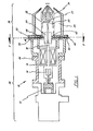
- Figure 1, which is a sectional pictorial view of an instrument including a charged particle analyzer embodying the principles of the present invention;
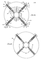
- Figure 2A, which is a cross-sectional view of the analyzer shown in Figure 1 taken along the line 2-2 thereof;
- Figure 2B, which is a cross-sectional view depicting another embodiment of the present invention; and
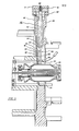
- Figure 3, which is another sectional view of a portion of an analyzer.
- Although the present invention generally relates to any charged particle spectroscopic instrument,-the following description pertains to an electron spectroscope, in particular, an Auger electron spectroscope.
- An Auger electron spectroscopic instrument, generally indicated at (10) in Figure 1, embodying the principles of the present invention, includes an electron beam source (12), having beam control elements including: a beam blanking element (14), a condenser lens (16), first beam steering plates (18), a variable objective aperture (20), second beam steering plates (22), and a fixed objective lens (24). The instrument (10) further includes an Auger electron analyzer (26) including, in this embodiment, a cylindrical mirror analyzer,(28), a collector assembly (30) and an alignment assembly (32).
- As known in the art, the above elements are encased within the interior of a housing (34) which, during operation, is pumped down to an ultra-high vacuum (herein the term "ultra-high vacuum" is used to designate a pressure of less than about 10-9torr).
- The electron beam source can be of a conventional design, for example, such as that described in U.S. Patent No. 4,205,226, the entirety of which is incorporated by reference herein. Further, the conventional beam focusing and shaping elements discussed above are also described sufficiently therein and further description thereof is not believed to be warranted for a complete understanding of the present invention.
- The departure from the conventional instrument which is the subject of the present invention is the provision of the alignment assembly (32) between the target side (36) and the beam source side (38) of the collector assembly (30).
- In the preferred embodiment, the alignment assembly(32), as shown in Figure 2, includes a flange plate (40) having an aperture (42) therethrough. Preferably, the aperture (42) is circular and coaxial with the flange plate (40) and has a diameter of about 4 cm and which loosely accepts the collector assembly (30) therewithin. The flange plate (40) further includes a plurality of spaced-apart throughbores (44) extending from the perimeter (46) of the flange plate (40) and communicating with the aperture (42). In the preferred embodiment, there are four throughbores (44) equally spaced about the perimeter (46). Of course, as will be readily apparent from the description below, as few as three throughbores (44) would also suffice. Preferably, although not necessarily, the throughbores (44) all lie in the same plane, which plane is substantially perpendicular to the axis of the beam path.
- In this embodiment, each throughbore (44) includes a plunger (48) extendable into, and retractable from, the aperture (42) by a push rod (50) controllable external the perimeter (46) of the flange plate (40). Each push rod (50) extends through a bellows (52) within the throughbore (44), which bellows (52) is capable of sustaining an ultra-high vacuum thereacross. One such bellows (52) is manufactured and marketed as part number 321-4-X-2 by CAJON Company of Solon, Ohio.
- In one specific embodiment, the flange plate (40) has an outside diameter of about 25 cm and a thickness of about 2.5 cm. Each of the throughbores (44) includes a comparatively wider portion (54) which extends inwardly from the perimeter (46) and a comparatively narrower portion (56) which exits into the aperture (42). A plunger retaining shoulder (58) is thus formed within the throughbore (44) at the interface. Preferably, the comparatively wider portion (54) has a diameter of about 1.2 cm and the comparatively narrower portion (56) has a diameter of about 0.25 cm.
- In this embodiment, the plunger (48) includes a head section,(60) having a diameter comparatively larger than the diameter of the narrower portion (56), which diameter is cooperatively compatible with movement within the wider portion (54), which head section (60), when the plunger (48) is fully extended, rests upon shoulder (58). The plunger (48) also includes a contact rod (62) extending from the head section (60) and extending through the comparatively narrower portion (56) of the throughbore.
- The push rod (50) contacts the head section (60) at one end (64) thereof and extends outwardly therefrom. Preferably, the push rod (50) includes a threaded portion (66) at the other end (68) thereof, which threaded portion (66) is threaded into a threaded bore (70) of a flange (72) affixed to the perimeter (46) of the flange plate (40). Thus, the push rod (50), by means of a screwdriver, for example, can be urged toward the aperture (42) or withdrawn therefrom.
- In practice, the push rods (50) are used in conjunction with the plunger (48) as a means for positioning and securing the collector assembly (30) within the housing (34).
- In an alternative embodiment, shown in Figure 2B two adjacent throughbores (44A) are provided with plungers (48) each being urged toward the aperture (42) by means of a spring (74). Further, the throughbores (44A) are sealed, for example, by known techniques such as welding, to maintain the desired ultra-high vacuum therewithin. Preferably, the springs (74) are capable of exerting a force between 10 to 50 pounds. Thus, in this embodiment the spring loaded plungers (48) provide sufficient counterforce to the adjustable plungers, i.e., those protruding from the throughbores (44), to allow both alignment of the collector assembly (30) but also sufficient counterforce to secure the assembly (30) in the aligned position.
- As shown in Figure 3, means (76) are included for retaining the collector assembly (30) in the direction parallel to the beam axis. The means (76) can be implemented by use of a plurality of Z springs. Thus, the collector assembly (30) can be angularly aligned with the beam axis by adjusting the plungers (48) from outside, or external to, the ultra-high vacuum.
- As shown in the embodiment of Figure 3, the throughbores (44) have a uniform diameter over the entire distance thereof. In such an arrangement the plunger (48) is rigidly affixed to the push rod (50). Further, to maintain, or enhance, the alignment of the plunger (48) a bracket (78) having a pair of guidearms (80) affixed thereto is provided such that the guide arms (80) extend into the aperture (42). The guide arms (80) are provided with guide holes (82) through which the contact rod (62) of the plunger (48) is passed. Preferably, the axes of the guide holes (82) are aligned with the axis of the throughbore (44). In one particular arrangement, the flange plate (40) is configured to include mounting wall (84) extending beyond the throughbores (44) and into the aperture (42). The wall (84) has a reduced thickness compared to the thickness of the flange plate (40), which is cooperatively dimensioned such that the guide holes (82), are axially aligned with the throughbore (44) when the bracket (78) is rigidly affixed to the wall (84). The flange plate (40) can be configured using well known machining techniques.
- The preferred procedure of alignment is discussed below. The instrument (10) is assembled and provided with a target, for example, 0 a copper target, and a 3Kev beam having a diameter between 100A-100 micrometers is directed thereat. The push rods (50) are adjusted until the collector assembly (30) is receiving the maximum reflected electrons, i.e., the collector assembly (30) is centered on the elastic peak of liberated electrons. The entire procedure can be easily accomplished in 5 to 10 minutes and the alignment is 2 to 3 times more accurate than conventional systems.
- Although the present invention has been described herein by means of a preferred embodiment, it will be understood that other configurations and modifications can be made without departing from the spirit and scope of the present invention which is deemed limited only by the appended claims and the reasonable interpretation thereof.
Claims (12)
1. Assembly for aligning an element of a charged particle analyzer, said assembly comprising:
a plate having an aperture therethrough, said aperture being sized so as to loosely accept said element ;
a plurality of radial throughbores extending from the perimeter of said plate and communicating with said aperture;
means, extending through said throughbores, for positioning and securing said element within said aperture;
an ultra-high vacuum seal associated with, and located within, each said throughbore whereby an ultra-high vacuum is sustainable across said throughbore.
2. Assembly as claimed in claim 1 wherein:
each said throughbore includes a comparatively wider portion extending inwardly from the perimeter of said plate and a comparatively narrower portion exiting into said aperture, a shoulder being formed at the interface of said portions.
3. Assembly as claimed in claims 1 or 2 wherein:
said positioning means including a plunger and a push rod, one end of said plunger being extendable into, and retractable from, said aperture, via manipulation of said push rod, one end of said push rod extending beyond the end of said seal proximate the perimeter of said plate.
4. Assembly as claimed in claim 3 wherein:
said one end of said push rod carries external threads and extends into an internally threaded aperture of a positioning flange.
5. Assembly as claimed in claim 4 therein:
said positioning flange being rigidly affixed to said plate and axially aligned with said throughbore.
6. Assembly as claimed in claim 3 wherein:
said plunger includes a head section having a diameter comparatively larger tha n the diameter of said comparatively narrower portion of said throughbore.
7. Assembly as claimed in claims 1 or 2 wherein:
a number of said throughbores, but no more than half, include spring loaded plungers therein, said number of said throughbores being sealed near the perimeter of said plate, said plungers extending into said aperture.
8. Assembly as claimed in claim 7 wherein:
each of said spring loaded plungers is opposed to a throughbore having a plunger and a push rod.
9. Assembly as claimed in claims 1 or 2 wherein:
, said ultra-high vacuum seal includes a bellows capable of sustaining an ultra-high vacuum of at least 10-9 torr.
10. Assembly as claimed in claim 1 further comprising:
means associated with each throughbore and extending into said aperture, for guiding said positioning and securing means.
11. Assembly as claimed in claim 10 wherein:
said positioning and securing means includes a plunger, said plunger being extendable into and retractable from said aperture; and said guiding means includes a pair of guide arms, each arm having a guide hole therethrough through which said plunger passes.
12. Assembly as claimed in claim 11 further comprising:
a wall, integral with said plate and having a reduced thickness compared thereto, extending into said aperture, said wall being co-operatively dimensioned with said guiding means such that when said guiding means is affixed to said wall said guiding holes are axially aligned with said throughbore.
Applications Claiming Priority (2)
| Application Number | Priority Date | Filing Date | Title |
|---|---|---|---|
| US40493282A | 1982-08-02 | 1982-08-02 | |
| US404932 | 1999-09-24 |
Publications (1)
| Publication Number | Publication Date |
|---|---|
| EP0100525A2 true EP0100525A2 (en) | 1984-02-15 |
Family
ID=23601618
Family Applications (1)
| Application Number | Title | Priority Date | Filing Date |
|---|---|---|---|
| EP19830107403 Withdrawn EP0100525A2 (en) | 1982-08-02 | 1983-07-27 | Alignment assembly |
Country Status (2)
| Country | Link |
|---|---|
| EP (1) | EP0100525A2 (en) |
| JP (1) | JPS5925154A (en) |
Cited By (1)
| Publication number | Priority date | Publication date | Assignee | Title |
|---|---|---|---|---|
| EP2400525A3 (en) * | 2010-06-25 | 2012-03-28 | Hitachi High-Technologies Corporation | Mass spectrometer |
-
1983
- 1983-07-07 JP JP58122461A patent/JPS5925154A/en active Pending
- 1983-07-27 EP EP19830107403 patent/EP0100525A2/en not_active Withdrawn
Cited By (2)
| Publication number | Priority date | Publication date | Assignee | Title |
|---|---|---|---|---|
| EP2400525A3 (en) * | 2010-06-25 | 2012-03-28 | Hitachi High-Technologies Corporation | Mass spectrometer |
| US8669518B2 (en) | 2010-06-25 | 2014-03-11 | Hitachi High-Technologies Corporation | Mass spectrometer |
Also Published As
| Publication number | Publication date |
|---|---|
| JPS5925154A (en) | 1984-02-09 |
Similar Documents
| Publication | Publication Date | Title |
|---|---|---|
| US4330208A (en) | Process and apparatus for regulating the impact of a light beam on a target | |
| US6320194B1 (en) | Portable high resolution scanning electron microscope column using permanent magnet electron lenses | |
| EP0196958B1 (en) | Electron beam test probe for integrated-circuit testing | |
| Allyn et al. | Analyzer system capable of determining energy and direction of charged particles in ultrahigh vacuum | |
| US4563769A (en) | X-Ray generator device | |
| JPH03504059A (en) | High resolution plasma mass spectrometer | |
| US3783280A (en) | Method and apparatus for charged particle spectroscopy | |
| US4358680A (en) | Charged particle spectrometers | |
| US4544845A (en) | Electron gun with a field emission cathode and a magnetic lens | |
| US4870283A (en) | Electric multipole lens | |
| US5091645A (en) | Selectable-resolution charged-particle beam analyzers | |
| US3949221A (en) | Double-focussing mass spectrometer | |
| US4487469A (en) | Mounting socket for a proximity switch | |
| US4296323A (en) | Secondary emission mass spectrometer mechanism to be used with other instrumentation | |
| JP4523594B2 (en) | Particle optics device | |
| Skoczylas et al. | A proposed modular imaging system for photoelectron and electron probe microscopy with aberration correction, and for mirror microscopy and low-energy electron microscopy | |
| US4050037A (en) | Laser beam alignment | |
| JPS6334844A (en) | Ion analysis method and device for insulating materials | |
| US4829178A (en) | Apparatus for surface analysis | |
| US5920073A (en) | Optical system | |
| US4101778A (en) | Rod-shaped specimen holder for an optical corpuscular-beam apparatus | |
| GB2118361A (en) | Scanning electron beam apparatus | |
| JPS5925154A (en) | Alignment device for charged particle analyzer elements | |
| DE3127441C2 (en) | ||
| US3419717A (en) | Manipulator for accurately positioning specimens within an electron microscope or an electron diffraction camera |
Legal Events
| Date | Code | Title | Description |
|---|---|---|---|
| PUAI | Public reference made under article 153(3) epc to a published international application that has entered the european phase |
Free format text: ORIGINAL CODE: 0009012 |
|
| AK | Designated contracting states |
Designated state(s): DE FR GB |
|
| STAA | Information on the status of an ep patent application or granted ep patent |
Free format text: STATUS: THE APPLICATION HAS BEEN WITHDRAWN |
|
| 18W | Application withdrawn |
Withdrawal date: 19850515 |
|
| RIN1 | Information on inventor provided before grant (corrected) |
Inventor name: GERLACH, ROBERT L. |