EP0100559A1 - Procédé et dispositif de fabrication de tuyaux en matière plastique - Google Patents
Procédé et dispositif de fabrication de tuyaux en matière plastique Download PDFInfo
- Publication number
- EP0100559A1 EP0100559A1 EP83107706A EP83107706A EP0100559A1 EP 0100559 A1 EP0100559 A1 EP 0100559A1 EP 83107706 A EP83107706 A EP 83107706A EP 83107706 A EP83107706 A EP 83107706A EP 0100559 A1 EP0100559 A1 EP 0100559A1
- Authority
- EP
- European Patent Office
- Prior art keywords
- mandrel
- hose
- onto
- strip
- adjacent
- Prior art date
- Legal status (The legal status is an assumption and is not a legal conclusion. Google has not performed a legal analysis and makes no representation as to the accuracy of the status listed.)
- Withdrawn
Links
- 239000004033 plastic Substances 0.000 title claims abstract description 14
- 238000004519 manufacturing process Methods 0.000 title claims abstract description 13
- 238000000034 method Methods 0.000 title claims description 15
- 239000000463 material Substances 0.000 claims abstract description 10
- 238000004804 winding Methods 0.000 claims abstract description 6
- 238000001125 extrusion Methods 0.000 claims description 8
- 238000003466 welding Methods 0.000 claims description 7
- 239000004020 conductor Substances 0.000 claims description 6
- 238000001816 cooling Methods 0.000 claims description 6
- 238000007788 roughening Methods 0.000 claims description 2
- 239000012809 cooling fluid Substances 0.000 claims 1
- 238000007599 discharging Methods 0.000 claims 1
- 238000011144 upstream manufacturing Methods 0.000 claims 1
- 239000000428 dust Substances 0.000 description 4
- 239000004568 cement Substances 0.000 description 3
- 239000011796 hollow space material Substances 0.000 description 3
- 230000003014 reinforcing effect Effects 0.000 description 3
- 239000002131 composite material Substances 0.000 description 2
- 239000002826 coolant Substances 0.000 description 2
- XLYOFNOQVPJJNP-UHFFFAOYSA-N water Substances O XLYOFNOQVPJJNP-UHFFFAOYSA-N 0.000 description 2
- 238000005273 aeration Methods 0.000 description 1
- 230000009172 bursting Effects 0.000 description 1
- 230000000295 complement effect Effects 0.000 description 1
- 239000000498 cooling water Substances 0.000 description 1
- 230000008021 deposition Effects 0.000 description 1
- 238000009792 diffusion process Methods 0.000 description 1
- 238000005516 engineering process Methods 0.000 description 1
- 239000012530 fluid Substances 0.000 description 1
- 230000001939 inductive effect Effects 0.000 description 1
- 239000007788 liquid Substances 0.000 description 1
- 230000013011 mating Effects 0.000 description 1
- 238000002844 melting Methods 0.000 description 1
- 230000008018 melting Effects 0.000 description 1
Images

Classifications
-
- B—PERFORMING OPERATIONS; TRANSPORTING
- B29—WORKING OF PLASTICS; WORKING OF SUBSTANCES IN A PLASTIC STATE IN GENERAL
- B29C—SHAPING OR JOINING OF PLASTICS; SHAPING OF MATERIAL IN A PLASTIC STATE, NOT OTHERWISE PROVIDED FOR; AFTER-TREATMENT OF THE SHAPED PRODUCTS, e.g. REPAIRING
- B29C53/00—Shaping by bending, folding, twisting, straightening or flattening; Apparatus therefor
- B29C53/56—Winding and joining, e.g. winding spirally
- B29C53/58—Winding and joining, e.g. winding spirally helically
- B29C53/78—Winding and joining, e.g. winding spirally helically using profiled sheets or strips
-
- B—PERFORMING OPERATIONS; TRANSPORTING
- B29—WORKING OF PLASTICS; WORKING OF SUBSTANCES IN A PLASTIC STATE IN GENERAL
- B29C—SHAPING OR JOINING OF PLASTICS; SHAPING OF MATERIAL IN A PLASTIC STATE, NOT OTHERWISE PROVIDED FOR; AFTER-TREATMENT OF THE SHAPED PRODUCTS, e.g. REPAIRING
- B29C53/00—Shaping by bending, folding, twisting, straightening or flattening; Apparatus therefor
- B29C53/80—Component parts, details or accessories; Auxiliary operations
- B29C53/82—Cores or mandrels
- B29C53/821—Mandrels especially adapted for winding and joining
- B29C53/825—Mandrels especially adapted for winding and joining for continuous winding
- B29C53/827—Mandrels especially adapted for winding and joining for continuous winding formed by several elements rotating about their own axes
Definitions
- the present invention relates to the manufacturing of plastic hoses and more specifically to a process and an apparatus for such a maufacturing.
- the strip is spirally wound onto a mandrel, whereas downstream positioned dragging means take care of the removal of the hose from the mandrel as it is formed.
- a reinforcing member is embedded into the pipe wall, the reinforcing member being of a more rigid material, possibly coextruded with the material forming the afore said strip and which will form the wall of the final hose.
- Such a strip is wound around a rotating mandrel, the outer surface of which is formed by the cylindrical surface defined by a number of shafts which are mounted in a skew position with respect to the axis of said cylindrical surface, said shafts being driven into rotation around their own axis.
- the normal hoses namely hoses without reinforcing spiral core
- their manufacturing comprises the extrusion of a strip, essentially shaped as a narrow and deep U, and the spiral winding of the strip, often already cooled down, the adjacent turns being fused for instance by means of a cement and of a hot air jet, causing a partial and surface limited melting of the two lenghts of strip to be welded.
- Such a technology gives place to several problems and drawbacks both from the point of view of the thus obtained hose and from that of the manufacturing process and apparatus.
- thes hose having the aspect of a number of hollow ribs which are positioned in a crosswise manner with respect to the axis of the hose may show weakness at the welding areas which may lead to failures especially in the presence of water or air under pressure.
- the hose has a relevant axial compressibility whereby during the use, namely when air or a liquid under pressure flows within the hose and an abrupt pressure variation takes place, the lenght of the hose can abruptly vary and by a not negligible amount.
- the main pupose of the present invention is that of providing a process and an apparatus for the manufacturing of plastic hoses by which the above mentioned problems and drawbacks are essentially done away with.
- a more specific purpose of the present invention is that of providing a process and apparatus by which is is possible to continuously manufacture plastic hoses in which the possibility of deposition of dust and foreign material within the hose is essentially reduced and which are essentially not compressible in the axial direction.
- a further purpose of the present invention is that of providing a process and an apparatus by which improved plastic hoses can be manufactured.
- the apparatus according to the invention comprising an extrusion head capable of extruding a strip comprising in its cross-section at least one U shaped hollow rib and two side fins which can be overlapped to form with the fins of adjacent strips the continuous wall of a pipe, and a mandrel onto which said strip is spirally woud, said mandrel comprising a number of shafts each concomitanly rotating around its axis, said shafts being positioned so as to define a cylindrical envelope surface and being skewed with respect to the said cylindrical surface, characterized in that each said shaft has a surface portion provided with cross finnings capable of mating said U shaped hollow space of said rib of said extruded strip, said finnings being positioned so that the finnings of adjacent shafts follow the spiral winding lines of said strip onto said mandrel, and further characterized in that at the end remote from said finnings said shafts terminate in circumferential means capable of generating an adjustable friction between the pipe being formed and the
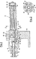
- the apparatus of the present invention comprises a frame 10, from which the forming mandrel 11 protrudes horizontally in a cantilevered fashion, whereas rearwardly a driving shaft 12 is mounted, being journalled in a cover casing 13 and driven into rotation from a pinion 14 which is in turn driven by a driving motor or gearing not shown.
- Suitable bearings 15 support the shaft 15 in its rotation.
- the shaft 12 is provided with a ring gear 16 meshed with a pinion 17, fastened to the rear end of a shaft 18.
- a hollow space 19 is provided in the frame 10, it being sealingly crossed by the shafts 18, the space 19 being connected through a fitting 20 with a cooling water feed.
- each shaft 18 is hollow and, at the hollow space 19, is provided with ports 21 through which water or other cooling medium enters the shafts 18, flowing throghout their length, and being then collected through the ducts 25, formed in the head part 26, in a central header 22 by which it is returned to an outlet fitting 23.
- the shafts 18 are positioned around a central support, which in the specific case in the header 22 ,so as to define a cylindrical envelope surface 24. At the same time the shafts 18 are skewed with respect to the axis of the cylindrical surface 24.
- a sleeve 32 for instance of rubber, is mounted at the end of the mandrel 11 .
- the sleeve 32 is in form of an expandable element in an adjustable manner, so as to be aligned or protrude by the desired height with respect to the surface 24 of the mandrel 11.
- Each shaft 18, in the fore part, namely that close to the frame 10, is provided with disks 27 which are positioned in a cross-wise manner with respect to the axis of the shaft and thus inclined therewith with respect to the axis of the mandrel 11.
- the disks 27 of adjacent shafts 18 are aligned according to planes which essentially define a spiral path with respect to the axis of the mandrel 11.
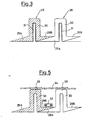
- the srrip being extruded generally indicated by reference 28, comprises two fins 29A and 29B and a U shaped rib 30, the internal space of which is indicated by the reference 31.
- the cavities 31 find support in the disks 17 for the whole distance necessary in order that the welding of the fins takes place and the pipe takes its, form without deformation of the ribs 28. Obviously it contributes to the strength uniformity of the final hose.
- the helicoidal motion of the pipe along the mandrel 11 ensures that the cavities 31 are disengaged from the disks 27 as the pipe advances.
- the necessary friction resistance can be generated in a different manner, such as for instance by roughening the surface of the end member 26 of the mandrel 11.
- the hose comprises also the electrical connection, between the energy soure positioned at one end and a whatsover tool or device mounted at the opposite end.
- a ribbon 34 is spirally wound outwardly of the rib 28 to close the spaces remaining between each rib and the adjacent one, whereby although the functionality of the hose is maintained unchganed the entry of dust and/or dirt between the ribs is avoided and the hose is prevented from being bent more than the working radius.
- the ribbon 34 is wound onto the top of the rib 28 and has a width greater than the distance between the mid-lines of two adjacent ribs, so as to close the cavity outwardly remaining between two adjacent ribs.
- the apparatus shall comprise means , per se known, for the . feed'ing of the conductor 33 and/or of the ribbon 34 in the desired and suitable position onto the mandrel 11.
Landscapes
- Engineering & Computer Science (AREA)
- Mechanical Engineering (AREA)
- Shaping Of Tube Ends By Bending Or Straightening (AREA)
Applications Claiming Priority (2)
| Application Number | Priority Date | Filing Date | Title |
|---|---|---|---|
| IT22756/82A IT1152336B (it) | 1982-08-06 | 1982-08-06 | Procedimento ed apparecchiatura per la fabbricazione di tubi flessibili in materiale plastico |
| IT2275682 | 1982-08-06 |
Publications (1)
| Publication Number | Publication Date |
|---|---|
| EP0100559A1 true EP0100559A1 (fr) | 1984-02-15 |
Family
ID=11200077
Family Applications (1)
| Application Number | Title | Priority Date | Filing Date |
|---|---|---|---|
| EP83107706A Withdrawn EP0100559A1 (fr) | 1982-08-06 | 1983-08-04 | Procédé et dispositif de fabrication de tuyaux en matière plastique |
Country Status (2)
| Country | Link |
|---|---|
| EP (1) | EP0100559A1 (fr) |
| IT (1) | IT1152336B (fr) |
Cited By (1)
| Publication number | Priority date | Publication date | Assignee | Title |
|---|---|---|---|---|
| EP0526382A1 (fr) * | 1991-06-03 | 1993-02-03 | Dimitris Th. Tsingopoulos | Dispositif et procédé pour fabriquer des tuyaux flexibles renforcés |
Citations (2)
| Publication number | Priority date | Publication date | Assignee | Title |
|---|---|---|---|---|
| DE2308418B2 (de) * | 1972-06-21 | 1976-04-08 | Petzetakis, Aristovoulos George, Moschaton, Piräus (Griechenland) | Verfahren und vorrichtung zum herstellen eines insbesondere grosskalibrigen rohres aus thermoplastischem kunststoff |
| US3997382A (en) * | 1972-02-29 | 1976-12-14 | Kakuichi Mfg. Co., Ltd. | Method of and apparatus for manufacturing reinforced flexible tubes |
-
1982
- 1982-08-06 IT IT22756/82A patent/IT1152336B/it active
-
1983
- 1983-08-04 EP EP83107706A patent/EP0100559A1/fr not_active Withdrawn
Patent Citations (2)
| Publication number | Priority date | Publication date | Assignee | Title |
|---|---|---|---|---|
| US3997382A (en) * | 1972-02-29 | 1976-12-14 | Kakuichi Mfg. Co., Ltd. | Method of and apparatus for manufacturing reinforced flexible tubes |
| DE2308418B2 (de) * | 1972-06-21 | 1976-04-08 | Petzetakis, Aristovoulos George, Moschaton, Piräus (Griechenland) | Verfahren und vorrichtung zum herstellen eines insbesondere grosskalibrigen rohres aus thermoplastischem kunststoff |
Cited By (1)
| Publication number | Priority date | Publication date | Assignee | Title |
|---|---|---|---|---|
| EP0526382A1 (fr) * | 1991-06-03 | 1993-02-03 | Dimitris Th. Tsingopoulos | Dispositif et procédé pour fabriquer des tuyaux flexibles renforcés |
Also Published As
| Publication number | Publication date |
|---|---|
| IT8222756A0 (it) | 1982-08-06 |
| IT1152336B (it) | 1986-12-31 |
Similar Documents
| Publication | Publication Date | Title |
|---|---|---|
| EP0134987B1 (fr) | Dispositif pour fabriquer un tuyau en matière plastique à enroulement hélicoidal | |
| KR860000805B1 (ko) | 주름진 튜우브의 제조방법 및 장치 | |
| US2502638A (en) | Method of extruding plastics in tubular form and wrapping the tubing | |
| US4033808A (en) | Apparatus for the production of hollow bodies, especially large-diameter ducts from thermoplastic synthetic resin | |
| US3917500A (en) | Method for the production of hollow bodies, especially large-diameter ducts from thermoplastic synthetic resin | |
| CA1136816A (fr) | Procede et appareillage pour l'extrusion de tubes plastiques a parois composites | |
| US2630157A (en) | Method of making reinforced suction cleaner hose | |
| US4006599A (en) | Plastic drain pipe and apparatus for producing the same | |
| US4528148A (en) | Method and apparatus for forming grooves in an optical fiber support | |
| CA1108042A (fr) | Rouleau presseur et methode de guipage de tuyaux en acier avec une bande thermoplastique | |
| EP0100559A1 (fr) | Procédé et dispositif de fabrication de tuyaux en matière plastique | |
| EP0500216B1 (fr) | Intérieur démontable pour une couvre-joint tubulaire de retrait et méthode et appareil pour production similaire | |
| EP0385479B1 (fr) | Dispositif de fabrication de tuyaux possédant une nervure hélicoidale | |
| JPH0262755B2 (fr) | ||
| IE37763L (en) | Pipe formed from helically wound hollow element | |
| JP2000046256A (ja) | コルゲ―ト管及びその製造方法 | |
| JPH0737081B2 (ja) | 合成樹脂管の製造方法および製造装置 | |
| US3966104A (en) | Apparatus for severing reinforced elastomeric conduit | |
| JP2567669B2 (ja) | 合成樹脂螺旋管の製造装置 | |
| CN116867633A (zh) | 由热塑性材料生产盘管的方法和设备 | |
| US4470793A (en) | Extruder for extruding pasta in the form of a thin continuous strip | |
| CN219381543U (zh) | 一种塑料挤出机 | |
| KR20040099720A (ko) | 관 이음구와 그 성형 장치 및 방법 | |
| CN218948477U (zh) | 一种中空壁缠绕管生产设备 | |
| JP4422859B2 (ja) | 合成樹脂成形体の押出成形方法およびホースの成形方法 |
Legal Events
| Date | Code | Title | Description |
|---|---|---|---|
| PUAI | Public reference made under article 153(3) epc to a published international application that has entered the european phase |
Free format text: ORIGINAL CODE: 0009012 |
|
| AK | Designated contracting states |
Designated state(s): AT BE CH DE FR GB LI LU NL SE |
|
| STAA | Information on the status of an ep patent application or granted ep patent |
Free format text: STATUS: THE APPLICATION IS DEEMED TO BE WITHDRAWN |
|
| 18D | Application deemed to be withdrawn |
Effective date: 19850123 |