EP0100560A2 - Shaped member forming the playing lines of tennis courts - Google Patents
Shaped member forming the playing lines of tennis courts Download PDFInfo
- Publication number
- EP0100560A2 EP0100560A2 EP83107716A EP83107716A EP0100560A2 EP 0100560 A2 EP0100560 A2 EP 0100560A2 EP 83107716 A EP83107716 A EP 83107716A EP 83107716 A EP83107716 A EP 83107716A EP 0100560 A2 EP0100560 A2 EP 0100560A2
- Authority
- EP
- European Patent Office
- Prior art keywords
- plug
- profile piece
- webs
- line profile
- line
- Prior art date
- Legal status (The legal status is an assumption and is not a legal conclusion. Google has not performed a legal analysis and makes no representation as to the accuracy of the status listed.)
- Granted
Links
- XLYOFNOQVPJJNP-UHFFFAOYSA-N water Substances O XLYOFNOQVPJJNP-UHFFFAOYSA-N 0.000 claims abstract description 19
- 238000009434 installation Methods 0.000 abstract description 5
- 238000004873 anchoring Methods 0.000 abstract description 3
- 239000002956 ash Substances 0.000 description 5
- 239000000463 material Substances 0.000 description 5
- 238000004140 cleaning Methods 0.000 description 3
- 238000010276 construction Methods 0.000 description 3
- 230000015572 biosynthetic process Effects 0.000 description 2
- 239000002893 slag Substances 0.000 description 2
- 235000002918 Fraxinus excelsior Nutrition 0.000 description 1
- 230000006978 adaptation Effects 0.000 description 1
- 238000005056 compaction Methods 0.000 description 1
- 230000000694 effects Effects 0.000 description 1
- 238000011010 flushing procedure Methods 0.000 description 1
- 230000008595 infiltration Effects 0.000 description 1
- 238000001764 infiltration Methods 0.000 description 1
- 238000003780 insertion Methods 0.000 description 1
- 230000037431 insertion Effects 0.000 description 1
- 238000012423 maintenance Methods 0.000 description 1
- 238000004519 manufacturing process Methods 0.000 description 1
- 239000002689 soil Substances 0.000 description 1
- 239000002352 surface water Substances 0.000 description 1
Images


Classifications
-
- A—HUMAN NECESSITIES
- A63—SPORTS; GAMES; AMUSEMENTS
- A63C—SKATES; SKIS; ROLLER SKATES; DESIGN OR LAYOUT OF COURTS, RINKS OR THE LIKE
- A63C19/00—Design or layout of playing courts, rinks, bowling greens or areas for water-skiing; Covers therefor
- A63C19/06—Apparatus for setting-out or dividing courts
- A63C19/065—Line markings, e.g. tapes; Methods therefor
-
- E—FIXED CONSTRUCTIONS
- E01—CONSTRUCTION OF ROADS, RAILWAYS, OR BRIDGES
- E01C—CONSTRUCTION OF, OR SURFACES FOR, ROADS, SPORTS GROUNDS, OR THE LIKE; MACHINES OR AUXILIARY TOOLS FOR CONSTRUCTION OR REPAIR
- E01C13/00—Pavings or foundations specially adapted for playgrounds or sports grounds; Drainage, irrigation or heating of sports grounds
- E01C13/02—Foundations, e.g. with drainage or heating arrangements
-
- E—FIXED CONSTRUCTIONS
- E01—CONSTRUCTION OF ROADS, RAILWAYS, OR BRIDGES
- E01F—ADDITIONAL WORK, SUCH AS EQUIPPING ROADS OR THE CONSTRUCTION OF PLATFORMS, HELICOPTER LANDING STAGES, SIGNS, SNOW FENCES, OR THE LIKE
- E01F9/00—Arrangement of road signs or traffic signals; Arrangements for enforcing caution
- E01F9/50—Road surface markings; Kerbs or road edgings, specially adapted for alerting road users
- E01F9/576—Traffic lines
- E01F9/578—Traffic lines consisting of preformed elements, e.g. tapes, block-type elements specially designed or arranged to make up a traffic line
-
- E—FIXED CONSTRUCTIONS
- E02—HYDRAULIC ENGINEERING; FOUNDATIONS; SOIL SHIFTING
- E02B—HYDRAULIC ENGINEERING
- E02B11/00—Drainage of soil, e.g. for agricultural purposes
- E02B11/005—Drainage conduits
Definitions
- the invention relates to a line profile piece for tennis courts, with a cover strip forming the line and plug bars located underneath.
- Tennis courts usually have a three-layer structure. Under a cover layer of mostly reddish ash and with a thickness of approx. 2.5 cm there is a dynamic layer of relatively coarse slag with a thickness of 4-6 cm and underneath this a base layer made of gravel with a thickness of 1o - 2o cm.
- the generic, known line profile pieces are in no way suitable for solving the problem of such surface residual water removal.
- the plug bars located on the underside of their cover strips only have an anchoring function. With them, the line profile pieces, instead of the previous nailing of simple cover strips, are anchored in the cover layer and the dynamic layer, into which the plug-in bars are pressed during installation.
- the present invention has for its object to provide a line profile piece of the generic type, which is able to collect residual surface water remaining in the line area.
- the solution according to the invention is that the line profile piece is designed with a bottom as a closed hollow profile and the lateral plug-in webs and the cover strip are provided with water passage slots.
- an embodiment is also quite useful in which the bottom area of the closed hollow profile is also provided with water passage slots without lateral connections to drainage systems, which leads to a relatively rapid infiltration of the collected water underground, especially since the closed hollow profile normally comes close to the Base layer is approaching and in this layer area there is no longer any compaction which significantly impairs the seepage.
- Such a line profile piece can also be easily retrofitted into existing tennis courts. It can be easily removed for thorough cleaning and then reinserted. If the line profile piece freezes up once, it is simply rolled in again with the ash material. A level alignment of such a line profile piece is also completely problem-free, as is the covering with fresh ash material if necessary.
- the installation and maintenance tasks are so simple that they can be easily carried out by the site manager.
- the price increase compared to conventional line profile pieces without a water-collecting effect is also very low.
- the profile piece has a cover strip 1 with its upper side formed by a corresponding design, to which two plug-in webs 2 are formed on the underside, which at least in their lower areas are provided with anchoring ribs 3 on the outside are provided.
- the profile piece is designed as a closed hollow profile in that a bottom bar 4 is detachably arranged between the two plug bars 3.
- the bottom bar 4 is designed as an insertion bar and in the plug bars 3 are located opposite one another in FIG Different height receiving grooves 5 are provided, in each of which the bottom bar 4 can be inserted at the desired height.
- the bottom bar 4 is arranged at such a height that it lies at most up to the ballast base layer after installation, but the bottom bar 4 does not need to be pressed into the base layer during installation.
- the lateral plug-in webs 2 and the cover strip 1 forming the line are provided with narrow, elongated water passage slots 6 which are dimensioned so narrow that the ashes of the cover layer cannot essentially pass through.
- the line profile piece can be removed from the floor for cleaning purposes. Particularly good cleaning is ensured by the possibility of removing the bottom bar 4.
- the baseline of a tennis court is formed from such a line profile piece, there is the possibility of creating connections to the existing drainage or drainage system of the court at the lateral corners, so that despite the relatively small volume of the hollow profile, considerable amounts of residual water are drained from the baseline area can.
- the rear T-line of the square is formed in this way.
- the bottom rail 4 is also expediently provided with water passage slits through which the collected residual water can then seep into the ground, in particular into the highly water-permeable ballast base layer.
- the line profile piece is particularly easy to manufacture. It consists of a closed, one-piece hollow profile, again with the cover strip 1, lateral plug-in webs 2 and a base which is now designed as a base part 4 'tapering downwards in a wedge shape.
- the wedge-shaped bottom region 4 ' is expedient, as are the plug-in webs 2 and the cover strip 1, with water passage slots 4.
- FIG. 3 shows a further embodiment variant of the line profile piece according to FIG.
- small downward-pointing clamping webs 1a are formed under the top of the cover strip 1, which have outward-facing locking lugs 1b, for which 2 receiving grooves 2a are provided in the inner edge region of the lateral webs. After assembly, the clamping webs 1a thus lie within the lateral webs 2.
Landscapes
- Engineering & Computer Science (AREA)
- Civil Engineering (AREA)
- Structural Engineering (AREA)
- Architecture (AREA)
- General Engineering & Computer Science (AREA)
- Life Sciences & Earth Sciences (AREA)
- Agronomy & Crop Science (AREA)
- Mechanical Engineering (AREA)
- Road Paving Structures (AREA)
- Coating Apparatus (AREA)
- Golf Clubs (AREA)
- Toys (AREA)
Abstract
Das Linienprofilstück für Tennisplätze hat an der Oberseite eine die Linie bildende Deckleiste (1), an der unterseitig zwei Steckstege (2) vorgesehen sind, die Verankerungsrippen (3) haben können. Durch eine Bodenleiste (4) zwischen den Steckstegen (2) ist das Profilstück als geschlossenes Hohlprofil ausgebildet. Die Steckstege (2) sind so lang und die Bodenleiste (4) ist in einer solchen Höhenlage angeordnet, daß letztere nach dem Einbau bis höchstens an die Schotter-Tragschicht des Tennisplatzes heranreicht. Die Steckstege (2) und die Deckleiste (1) sind mit schmalen länglichen Wasserdurchlaßschlietzen (6) versehen. Ein solches Linienprofilstück kann leicht in einem Tennistennenplatz verlegt werden und ist in der Lage, insbesondere im Grundlinienbereich das Wasser aus kleinen Restpfützem aufzunehmen und gegebenenfalls bei seitlichem Dränageanschluß auch abzuführen.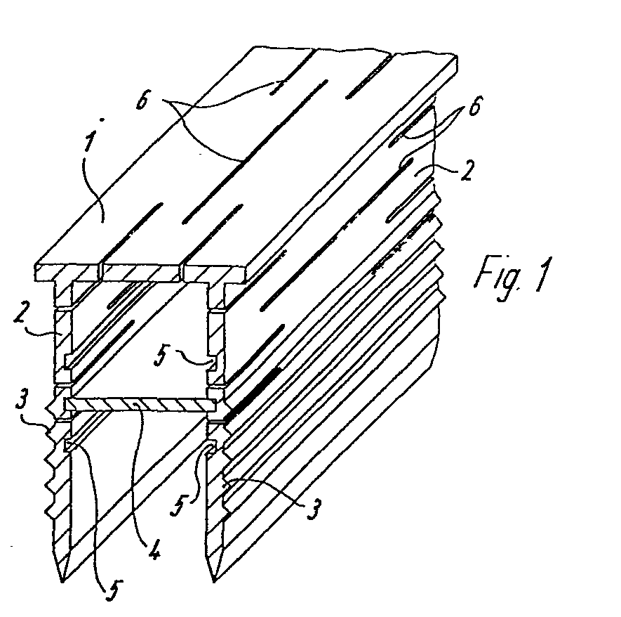
Description
Die Erfindung betrifft ein Linienprofilstück für Tennisplätze, mit einer die Linie bildenden Deckleiste und darunter befindlichen Steckstegen.The invention relates to a line profile piece for tennis courts, with a cover strip forming the line and plug bars located underneath.
Tennistennenplätze haben üblicherweise einen dreischichtigen Aufbau. Unter einer Deckschicht aus meist rötlicher Asche und in einer Stärke von ca. 2,5 cm befindet sich eine dynamische Schicht aus relativ grober Schlacke in einer Stärke von 4-6 cm und unter dieser eine Tragschicht aus Schotter in einer Stärke von 1o--2o cm.Tennis courts usually have a three-layer structure. Under a cover layer of mostly reddish ash and with a thickness of approx. 2.5 cm there is a dynamic layer of relatively coarse slag with a thickness of 4-6 cm and underneath this a base layer made of gravel with a thickness of 1o - 2o cm.
Bei schon länger bespielten Plätzen läßt sich nun immer wieder beobachten, daß nach Regenfällen gerade im Bereich der Grundlinie das Regenwasser nicht oder nur sehr langsam versickert, so daß der Platz nach dem Regen wegen dieser relativ kleinen Restpfützen insbesondere im Grundlinienbereich noch nicht wieder bespielt werden kann. Die Erscheinung ist darauf zurückzuführen, daß im normalen Spielbetrieb das Deckschichtmaterial gerade im Bereich der Grundlinie besonders verdichtet wird und daß infolge des normalerweise gerade hier sehr starken Verschleißes am Deckschichtmaterial besonders viel Feinanteile anfallen, die die Deckschicht in besonderem Maße verdichten. Darüberhinaus kommt es in diesem Bereich auch im besonderen Maße zu einer Muldenbildung, was die Pfützenbildung auch noch begünstigt. Vergleichbare Erscheinungen treten auch häufig noch im Bereich der T-Linien auf, insbesondere nach einer hohen Platzbelastung mit Doppelspielen.In the case of places that have been used for a long time, it can now be observed again and again that after rainfalls, especially in the area of the baseline, the rainwater does not seep away or only very slowly, so that the place cannot be used again after the rain because of these relatively small puddles, especially in the baseline area . The phenomenon is due to the fact that, in normal play, the cover layer material is particularly compacted, particularly in the area of the baseline, and that as a result of the wear on the cover layer material, which is usually very strong here, a particularly large amount of fines are produced, which particularly affect the cover layer Compact dimensions. In addition, trough formation occurs to a particular extent in this area, which also favors puddle formation. Comparable phenomena also often occur in the area of the T-lines, especially after a lot of space with double games.
Die gattungsgemäßen, vorbekannten Linienprofilstücke sind in keiner Weise dazu geeignet, das Problem einer derartigen Oberflächenrestwasserbeseitigung zu lösen. Die an der Unterseite ihrer Deckleisten befindlichen Steckstege haben ausschließlich eine Verankerungsfunktion. Mit ihnen werden - die Linienprofilstücke, anstelle des früheren Vernagelns einfacher Deckleisten, in der Deckschicht und der dynamischen Schicht verankert, in die die Steckstege beim Verlegen hineingedrückt werden.The generic, known line profile pieces are in no way suitable for solving the problem of such surface residual water removal. The plug bars located on the underside of their cover strips only have an anchoring function. With them, the line profile pieces, instead of the previous nailing of simple cover strips, are anchored in the cover layer and the dynamic layer, into which the plug-in bars are pressed during installation.
Es ist andererseits allgemein im Sportstättenbau bekannt, entsprechend ihres Funktionszweckes großvolumige Dränagerohre, die bis tief in die Tragschichten hinein verlegt werden, oberseitig mit bündig zum Sportstättenbelag im übrigen liegenden Deckelelementen zu versehen, die beispielsweise bei Teilbereichen von Laufbahnen auch Linienfunktion haben können. Es ist dabei auch vorgeschlagen worden, derartige Dränagerohre im Linienbereich von Tennisplätzen zu verlegen und sie in ihrem oberen Bereich mit einer im Verhältnis zu ihrer Querdimension schmalen schlitzartigen Öffnung zu versehen, auf die dann eine Deckleiste gesetzt werden kann, die oberseitig als Linie ausgestaltet ist und die auch mit Wasserdurchlaßschlitzen versehen sein kann.On the other hand, it is generally known in sports facility construction to provide large-volume drainage pipes, which are laid deep into the base layers, with top cover elements that are flush with the sports facility surface and that can also have a line function, for example, in partial areas of running tracks. It has also been proposed to lay such drainage pipes in the line area of tennis courts and to narrow them in their upper area in relation to their transverse dimension to provide slot-like opening, on which a cover strip can then be placed, which is configured as a line on the upper side and which can also be provided with water passage slots.
Abgesehen davon, daß vorhandene Tennisplätze nicht nachträglich sinnvoll mit derartigen Dränagerohren versehen werden können, weil dieses ein Aufgraben des Platzs bis tief in die Tragschicht hinein erfordern würde, wäre auch die Neuanlage von Tennisplätzen mit derartigen die Liniendeckleiste tragenden Dränagerohren sehr kostenaufwendig. Die verschiedenen Aufbauschichten der Plätze werden nämlich maschinell aufgebracht und ein ausgelegtes Dränagerohr wäre dabei so störend, daß es immer noch kostengünstiger wäre, die Schichten erst vollständig ohne Dränagerohr aufzubringen und sie dann im Linienbereich zum Verlegen des Dränagerohres wieder aufzugraben. Ein derartiges Dränagerohr führt naturgemäß auch zu einer schnellen Beseitigung des Restwassers insbesondere im Grundlinienbereich eines Tennisplatzes, hat jedoch in erster Linie die Funktion einer schnellen und vollständigen Flächenentwässerung insgesamt und dient entsprechend der Dränierung in großeren Dränage- und Abflußleitungssystemen der Abfuhr von sich ausgehend von einer wasserundurchlässigen Bodenschicht hochstauendem Bodenwasser.In addition to the fact that existing tennis courts cannot be meaningfully provided with such drainage pipes because this would require digging the court deep into the base course, the creation of new tennis courts with such drainage pipes carrying the line cover strip would also be very expensive. The various construction layers of the squares are applied by machine and a drainage pipe designed would be so annoying that it would still be more cost-effective to apply the layers completely without a drainage pipe and then dig them up again in the line area to lay the drainage pipe. Such a drainage pipe naturally also leads to a quick removal of the residual water, especially in the baseline area of a tennis court, but primarily has the function of a quick and complete drainage of the entire area and serves, in accordance with the drainage in larger drainage and drainage pipe systems, for the drainage from an impermeable layer Bottom layer of impounded soil water.
Problematisch ist bei der Verwendung derartiger, bis tief in die Tragschicht reichender Dränagerohre im Tennisplatzbau auch, daß keinerlei Angleichung der Niveaulage der Linie an spätere Höhenveränderungen der Deckschicht, die durch Abnutzung und Wiederauftrag neuen Materiales auftreten können, möglich ist. Wenn darüberhinaus im Winter bei starken Frösten der Boden so tief friert, daß das Dränagerohr selbst aus dem Boden hochkommt, ist eine einfache Wiederherstellung praktisch unmöglich. Der Tennisplatz muß in den betroffenen Bereichen wiederum bis tief in die Tragschicht hinein aufgegraben werden. Sollte ferner ein derartiges Dränegerohr einmal sich so stark zugesetzt haben, daß auch die an sich problemlose Spülung des Rohrsystemes nicht mehr weiterhilft, würde erneut der sehr komplizierte und arbeitsaufwendige Ausbau mit womöglich nachträglichem Wiedereinbau erforderlich.Another problem with the use of such drainage pipes reaching deep into the base layer in tennis court construction is that there is no adjustment of the level of the line to subsequent changes in the height of the cover layer caused by wear and reapplication new material can occur is possible. In addition, if the ground freezes so deeply in strong frosts in winter that the drainage pipe itself comes up from the ground, simple restoration is practically impossible. The tennis court must again be dug deep into the base layer in the affected areas. In addition, if such a drainage tube had become so clogged that even the flushing of the pipe system, which was problem-free, would no longer help, the very complicated and labor-intensive removal with possibly subsequent reinstallation would be necessary.
Der vorliegenden Erfindung liegt die Aufgabe zugrunde, ein Linienprofilstück der gattungsgemäßen Art zu schaffen, das in der Lage ist, im Linienbereich verbleibendes Oberflächenrestwasser zu sammeln.The present invention has for its object to provide a line profile piece of the generic type, which is able to collect residual surface water remaining in the line area.
Die erfindungsgemäße Lösung besteht darin, daß das Linienprofilstück mit einem Boden als geschlossenes Hohlprofil ausgebildet ist und die seitlichen Steckstege sowie die Deckleiste mit Wasserdurchlaßschlitzen versehen sind.The solution according to the invention is that the line profile piece is designed with a bottom as a closed hollow profile and the lateral plug-in webs and the cover strip are provided with water passage slots.
Durch diese Ausgestaltung ist unterhalb der die Linie bildenden Deckleiste ein kleiner Hohlkörper geschaffen, der im Hinblick auf die übliche Länge bzw. Tiefe der Steckstege nach dem Verlegen allenfalls bis an die Schotter-Tragschicht heranreicht, dessen Volumen aber andererseits völlig ausreicht, Restwasser im Linienbereich aus dem angrenzenden stark verdichteten Deckschichtbereich aufzunehmen und in sich zu sammeln, so daß der Platz insgesamt sehr viel schneller wieder bespielbar ist. Schließt man, was ohne weiteres möglich ist, ein derartiges Linienprofilstück, das beispielsweise die Grundlinie eines Tennisplatzes bildet, seitlich an etwaig vorhandene Dränage- oder Abflußsysteme an, kann das gesammtelte Wasser nach dort abgegeben werden. In einem solchen Fall kann ein derartiges Linienprofilstück trotz des kleinen Hohlkörpervolumens doch erhebliche Restwassermengen schnell beseitigen. Es ist andererseits aber auch eine Ausführungsform durchaus brauchbar, bei der man ohne seitliche Anschlüsse an Abflußsysteme den Bodenbereich des geschlossenen Hohlprofiles ebenfalls mit Wasserdurchlaßschlitzen versieht, was zu einem relativ schnellen Versickern des gesammelten Wassers im Untergrund führt, zumal das geschlossene Hohlprofil normalerweise bis dicht an die Tragschicht heranreicht und in diesem Schichtbereich ein das Versickern erheblich beeinträchtigendes Verdichten nicht mehr auftritt.With this design, a small hollow body is created below the cover strip forming the line, which in view of the usual length or depth of the plug-in webs reaches after the laying at most up to the ballast base layer, but whose volume is completely sufficient on the other hand, residual water in the line area the adjacent heavily compacted deck Record layer area and collect in itself, so that the space can be used much faster again. If, as is readily possible, such a line profile piece, which for example forms the baseline of a tennis court, is laterally connected to any existing drainage or drainage systems, the collected water can be discharged there. In such a case, despite the small volume of the hollow body, such a line profile piece can quickly remove considerable amounts of residual water. On the other hand, however, an embodiment is also quite useful in which the bottom area of the closed hollow profile is also provided with water passage slots without lateral connections to drainage systems, which leads to a relatively rapid infiltration of the collected water underground, especially since the closed hollow profile normally comes close to the Base layer is approaching and in this layer area there is no longer any compaction which significantly impairs the seepage.
Ein derartiges Linienprofilstück kann auch völlig problemlos nachträglich in bestehende Tennisplätze verlegt werden. Es kann zur gründlichen Reinigung problemlos herausgenommen werden und danach wieder eingelegt werden. Friert das Linienprofilstück einmal hoch, wird es einfach mit dem Aschenmaterial wieder eingewalzt. Eine Niveauausrichtung eines derartigen Linienprofilstückes ist ebenfalls völlig problemlos, ebenso im Bedarfsfall die Andeckung mit frischem Aschenmaterial. Die Verlege- und die Wartungsarbeften sind so einfach, daß sie vom Platzwart der Anlage problemlos durchzuführen sind. Auch ist die Verteuerung gegenüber den herkömmlichen Linienprofilstücken ohne wassersammelnde Wirkung nur sehr gering.Such a line profile piece can also be easily retrofitted into existing tennis courts. It can be easily removed for thorough cleaning and then reinserted. If the line profile piece freezes up once, it is simply rolled in again with the ash material. A level alignment of such a line profile piece is also completely problem-free, as is the covering with fresh ash material if necessary. The installation and maintenance tasks are so simple that they can be easily carried out by the site manager. The price increase compared to conventional line profile pieces without a water-collecting effect is also very low.
Weitere bevorzugte Ausgestaltungen derartiger Linienprofilstücke, die insbesondere deren zweckmäßige bauliche Ausgestaltung betreffen, sind in den Unteransprüchen gekennzeichnet.Further preferred configurations of such line profile pieces, which relate in particular to their expedient structural configuration, are characterized in the subclaims.
Ausführungsbeispiele derartiger Linienprofilstücke werden nachstehend unter Bezugnahme auf die Zeichnung näher beschrieben.Embodiments of such line profile pieces are described below with reference to the drawing.
Es zeigen
Figur 1 eine perspektivische, teilweise geschnittene Darstellung eines derartigen Linienprofilstückes,Figur 2 ein weiteres Ausführungsbeispiel in entsprechender Darstellung,Figur 3 ein drittes Ausführungsbeispiel in entsprechender Teildarstellung.
- FIG. 1 shows a perspective, partially sectioned illustration of such a line profile piece,
- FIG. 2 shows another exemplary embodiment in a corresponding representation,
- Figure 3 shows a third embodiment in a corresponding partial representation.
Bei dem in Figur 1 dargestellten Linienprofilstück für Tennentennisplätze weist das Profilstück eine mit ihrer Oberseite durch eine entsprechende Ausgestaltung die Linie bildende Deckleiste 1 auf, an die unterseitig zwei Steckstege 2 angeformt sind, die zumindest in ihren unteren Bereichen außenseitig mit Verankerungsrippen 3 versehen sind. Bei diesem Ausführungsbeispiel ist das Profilstück dadurch als geschlossenes Hohlprofil ausgebildet, daß zwischen den beiden Steckstegen 3 eine Bodenleiste 4 lösbar angeordnet ist. Die Bodenleiste 4 ist bei diesem Ausführungsbeispiel als Einschubleiste ausgebildet und in den Steckstegen 3 sind einander gegenüberliegend in verschiedenen Höhenlagen Aufnahmenuten 5 vorgesehen, in die jeweils die Bodenleiste 4 in der gewünschten Höhenlage eingeschoben werden kann. Auf diese Art und Weise ist eine leichte Anpassung an verschiedene Schichthöhen der Tennisplätze bezüglich ihrer dynamischen Schlackeschicht und ihrer aus Asche bestehenden Deckschicht möglich. Die Bodenleiste 4 wird jeweils in einer solchen Höhenlage angeordnet, daß sie nach dem Einbau bis höchstens an die Schotter-Tragschicht heranreichend liegt, die Bodenleiste 4 aber beim Einbau nicht etwa noch in die Tragschicht hineingedrückt zu werden braucht.In the line profile piece for tennis tennis places shown in FIG. 1, the profile piece has a
Die seitlichen Steckstege 2 und die die Linie bildende - Deckleiste 1 sind mit schmalen länglichen Wasserdurchlaßschlitzen 6 versehen, die so eng bemessen sind, daß auch die Asche der Deckschicht im wesentlichen nicht hindurchtreten kann. Zu Reinigungszwecken kann das Linienprofilstück aus dem Boden herausgenommen werden. Ein besonders gutes Reinigen ist durch die Möglichkeit der Herausnahme der Bodenleiste 4 gewährleistet.The lateral plug-in
Bildet man beispielsweise die Grundlinie eines Tennisplatzes aus einem derartigen Linienprofilstück, besteht die Möglichkeit, an den seitlichen Ecken Anschlüsse an das vorhandene Dränage- oder Abflußsystem des Platzes zu schaffen, so daß trotz des relativ kleinen Volumens des Hohlprofiles doch beträchtliche Oberflächenrestwassermengen aus dem Grundlinienbereich abgeführt werden können. Das gleiche gilt, wenn die hintere T-Linie des Platzes derart ausgebildet wird.If, for example, the baseline of a tennis court is formed from such a line profile piece, there is the possibility of creating connections to the existing drainage or drainage system of the court at the lateral corners, so that despite the relatively small volume of the hollow profile, considerable amounts of residual water are drained from the baseline area can. The same applies if the rear T-line of the square is formed in this way.
Sollen derartige seitliche Anschlüsse an Dränage-und Abflußsysteme nicht vorgesehen werden, wird zweckmäßig auch noch die Bodenleiste 4 mit Wasserdurchlaßschlitzen versehen, durch die hindurch dann das gesammelte Restwasser in den Boden, insbesondere in die gut wasserdurchlässige Schotter-Tragschicht hinein versickern kann.If such lateral connections to drainage and drainage systems are not to be provided, the
Bei dem in Figur 2 dargestellten Ausführungsbeispiel ist das Linienprofilstück besonders einfach herstellbar. Es besteht aus einem geschlossenen einstückigen Hohlprofil, wiederum mit der Deckleiste 1, seitlichen Steckstegen 2 und einem Boden, der jetzt als sich keilförmig nach unten verjüngender Bodenteil 4' ausgebildet ist. Hierdurch wird das Eindrücken des Linienprofilstückes in den Boden, also durch die Deckschicht und durch die dynamische Schicht, besonders begünstigt. Der keilförmige Bodenbereich 4' ist zweckmäßig, ebenso wie die Steckstege 2 und die Deckleiste 1, mit Wasserdurchlaßschlitzen 4 versehen.In the embodiment shown in Figure 2, the line profile piece is particularly easy to manufacture. It consists of a closed, one-piece hollow profile, again with the
Die Figur 3 zeigt eine weitere Ausführungsvariante des Linienprofilstückes nach Figur 2. Bei auch hier mit den Steckstegen 2 einstückigem, zweckmäßig wiederum keilförmigen Bodenbereich ist hier die Deckleiste 1 lösbar mit den oberen Randbereichen der Seitenstege 2 verbunden. Hierzu sind unter die Oberseite der Deckleiste 1 kleine nach unten weisende Klemmstege 1a angeformt, die nach außen weisende Rastnasen 1b haben, für die im Innenrandbereich der seitlichen Stege 2 Aufnahmenuten 2a vorgesehen sind. Nach der Montage liegen somit die Klemmstege 1a innerhalb der seitlichen Stege 2.FIG. 3 shows a further embodiment variant of the line profile piece according to FIG. For this purpose, small downward-pointing
Claims (7)
Priority Applications (1)
| Application Number | Priority Date | Filing Date | Title |
|---|---|---|---|
| AT83107716T ATE28129T1 (en) | 1982-08-04 | 1983-08-04 | LINE PROFILE FOR TENNIS COURTS. |
Applications Claiming Priority (2)
| Application Number | Priority Date | Filing Date | Title |
|---|---|---|---|
| DE3229045 | 1982-08-04 | ||
| DE19823229045 DE3229045A1 (en) | 1982-08-04 | 1982-08-04 | LINE PROFILE PIECE FOR TENNIS COURTS |
Publications (3)
| Publication Number | Publication Date |
|---|---|
| EP0100560A2 true EP0100560A2 (en) | 1984-02-15 |
| EP0100560A3 EP0100560A3 (en) | 1984-12-19 |
| EP0100560B1 EP0100560B1 (en) | 1987-07-08 |
Family
ID=6170061
Family Applications (1)
| Application Number | Title | Priority Date | Filing Date |
|---|---|---|---|
| EP83107716A Expired EP0100560B1 (en) | 1982-08-04 | 1983-08-04 | Shaped member forming the playing lines of tennis courts |
Country Status (3)
| Country | Link |
|---|---|
| EP (1) | EP0100560B1 (en) |
| AT (1) | ATE28129T1 (en) |
| DE (1) | DE3229045A1 (en) |
Cited By (3)
| Publication number | Priority date | Publication date | Assignee | Title |
|---|---|---|---|---|
| FR2691726A1 (en) * | 1992-05-29 | 1993-12-03 | Scores | Soft tennis court made of synthetic material - has drainage layer and surface with hexagonal section honeycomb layer between filled with dry or wet compacted pozzolana or zeolite |
| KR100823455B1 (en) | 2007-04-12 | 2008-04-21 | 권세혁 | Playground Line Indicator |
| WO2017212060A1 (en) * | 2016-06-09 | 2017-12-14 | De Denkfabriek Bvba | Method for producing a grate for a drain |
Families Citing this family (1)
| Publication number | Priority date | Publication date | Assignee | Title |
|---|---|---|---|---|
| CH720020A1 (en) * | 2022-09-08 | 2024-03-15 | Joseph Tennisplatzbau Ag | Line system for marking lines, especially for artificial turf pitches or sand-filled artificial turf pitches. |
Family Cites Families (9)
| Publication number | Priority date | Publication date | Assignee | Title |
|---|---|---|---|---|
| BE386883A (en) * | ||||
| DE256705C (en) * | ||||
| DE1578706A1 (en) * | 1966-05-12 | 1970-08-27 | Wilhelm Bader Appbau | Profile rail for permanent marking of the playing field |
| GB1184664A (en) * | 1966-12-15 | 1970-03-18 | Althon Contracting Ltd | An Improvement in or relating to Road and Land Drainage. |
| DE1943002A1 (en) * | 1969-08-23 | 1971-04-22 | Helmut Graap | Marking bar for tennis courts or the like. |
| DE2347869C2 (en) * | 1973-09-22 | 1982-08-12 | Klaus 7550 Rastatt Werner | Prefabricated component for a drainage channel |
| DE2506705A1 (en) * | 1975-02-18 | 1976-08-19 | Nordrohr Werke Kg | Sectioned drainage gutter for building into ground - comprises gutter component inserted in composite top edge and sidewall component |
| US4218059A (en) * | 1978-06-23 | 1980-08-19 | Eiden Sidney W | Field marker |
| EP0056238B1 (en) * | 1981-01-08 | 1984-07-25 | Otto geb. Herfeld, Heide | Drainage apparatus for sports fields |
-
1982
- 1982-08-04 DE DE19823229045 patent/DE3229045A1/en not_active Withdrawn
-
1983
- 1983-08-04 AT AT83107716T patent/ATE28129T1/en not_active IP Right Cessation
- 1983-08-04 EP EP83107716A patent/EP0100560B1/en not_active Expired
Cited By (3)
| Publication number | Priority date | Publication date | Assignee | Title |
|---|---|---|---|---|
| FR2691726A1 (en) * | 1992-05-29 | 1993-12-03 | Scores | Soft tennis court made of synthetic material - has drainage layer and surface with hexagonal section honeycomb layer between filled with dry or wet compacted pozzolana or zeolite |
| KR100823455B1 (en) | 2007-04-12 | 2008-04-21 | 권세혁 | Playground Line Indicator |
| WO2017212060A1 (en) * | 2016-06-09 | 2017-12-14 | De Denkfabriek Bvba | Method for producing a grate for a drain |
Also Published As
| Publication number | Publication date |
|---|---|
| DE3229045A1 (en) | 1984-02-09 |
| ATE28129T1 (en) | 1987-07-15 |
| EP0100560A3 (en) | 1984-12-19 |
| EP0100560B1 (en) | 1987-07-08 |
Similar Documents
| Publication | Publication Date | Title |
|---|---|---|
| DE69928530T2 (en) | PAVERS | |
| DE4416943C2 (en) | Development of a movement area for horses, especially for a riding arena | |
| DE3632620A1 (en) | Noise-reducing roadway paving (roadsurface) | |
| EP1291325A2 (en) | Drainage body segment for making a drain for collecting surface water | |
| DE3133420A1 (en) | LIMITING ELEMENT | |
| DE3617471A1 (en) | Preform made of concrete for dewatering structures | |
| DE3326109C2 (en) | Cobblestone | |
| DE4428482C2 (en) | Gutter stone | |
| EP0100560A2 (en) | Shaped member forming the playing lines of tennis courts | |
| DE69601306T2 (en) | DRAINAGE SYSTEM FOR ROADS | |
| DE3536409A1 (en) | Purpose-made block for channelling away surface water from earth-type coverings, and process for the production thereof | |
| DE19602414C2 (en) | Device for collecting and trickling surface water | |
| DE202008013316U1 (en) | Drainage system for surface water | |
| DE8222036U1 (en) | Line profile piece for tennis courts | |
| EP1234913A2 (en) | Drainage channel | |
| DE8124673U1 (en) | LIMITING ELEMENT FOR LIMITING OR SEPARATING DIFFERENT AREAS, IN PARTICULAR OUTDOORS | |
| EP0979327B1 (en) | Shaped block, especially a concrete block | |
| DE19847672C1 (en) | One-piece drainage component for installation beneath edge area of road surface has load accommodation points, which define locating surface on one side of component | |
| CH153142A (en) | Street gutter. | |
| AT230927B (en) | Shaped stone for transverse channels on hillside paths | |
| DE29609029U1 (en) | Artificial stone element | |
| DE29809590U1 (en) | Drainage device for paved surfaces and structures | |
| DE19735608A1 (en) | Grouting for floor slabs on balconies etc. | |
| AT367820B (en) | DRAINAGE ELEMENT FOR DRAINAGE OF THE EARTH | |
| AT520177B1 (en) | Drywall and intermediate stone therefor |
Legal Events
| Date | Code | Title | Description |
|---|---|---|---|
| PUAI | Public reference made under article 153(3) epc to a published international application that has entered the european phase |
Free format text: ORIGINAL CODE: 0009012 |
|
| AK | Designated contracting states |
Designated state(s): AT BE CH FR GB IT LI LU NL SE |
|
| 17P | Request for examination filed |
Effective date: 19840529 |
|
| PUAL | Search report despatched |
Free format text: ORIGINAL CODE: 0009013 |
|
| AK | Designated contracting states |
Designated state(s): AT BE CH FR GB IT LI LU NL SE |
|
| GRAA | (expected) grant |
Free format text: ORIGINAL CODE: 0009210 |
|
| AK | Designated contracting states |
Kind code of ref document: B1 Designated state(s): AT BE CH FR GB IT LI LU NL SE |
|
| PG25 | Lapsed in a contracting state [announced via postgrant information from national office to epo] |
Ref country code: IT Free format text: LAPSE BECAUSE OF FAILURE TO SUBMIT A TRANSLATION OF THE DESCRIPTION OR TO PAY THE FEE WITHIN THE PRESCRIBED TIME-LIMIT;WARNING: LAPSES OF ITALIAN PATENTS WITH EFFECTIVE DATE BEFORE 2007 MAY HAVE OCCURRED AT ANY TIME BEFORE 2007. THE CORRECT EFFECTIVE DATE MAY BE DIFFERENT FROM THE ONE RECORDED. Effective date: 19870708 Ref country code: BE Effective date: 19870708 |
|
| REF | Corresponds to: |
Ref document number: 28129 Country of ref document: AT Date of ref document: 19870715 Kind code of ref document: T |
|
| PG25 | Lapsed in a contracting state [announced via postgrant information from national office to epo] |
Ref country code: SE Effective date: 19870731 |
|
| PG25 | Lapsed in a contracting state [announced via postgrant information from national office to epo] |
Ref country code: LU Free format text: LAPSE BECAUSE OF NON-PAYMENT OF DUE FEES Effective date: 19870831 |
|
| ET | Fr: translation filed | ||
| PLBE | No opposition filed within time limit |
Free format text: ORIGINAL CODE: 0009261 |
|
| STAA | Information on the status of an ep patent application or granted ep patent |
Free format text: STATUS: NO OPPOSITION FILED WITHIN TIME LIMIT |
|
| 26N | No opposition filed | ||
| PGFP | Annual fee paid to national office [announced via postgrant information from national office to epo] |
Ref country code: FR Payment date: 19890630 Year of fee payment: 7 Ref country code: CH Payment date: 19890630 Year of fee payment: 7 |
|
| PGFP | Annual fee paid to national office [announced via postgrant information from national office to epo] |
Ref country code: NL Payment date: 19890831 Year of fee payment: 7 Ref country code: GB Payment date: 19890831 Year of fee payment: 7 Ref country code: AT Payment date: 19890831 Year of fee payment: 7 |
|
| PG25 | Lapsed in a contracting state [announced via postgrant information from national office to epo] |
Ref country code: GB Effective date: 19900804 Ref country code: AT Effective date: 19900804 |
|
| PG25 | Lapsed in a contracting state [announced via postgrant information from national office to epo] |
Ref country code: LI Effective date: 19900831 Ref country code: CH Effective date: 19900831 |
|
| PG25 | Lapsed in a contracting state [announced via postgrant information from national office to epo] |
Ref country code: NL Effective date: 19910301 |
|
| GBPC | Gb: european patent ceased through non-payment of renewal fee | ||
| NLV4 | Nl: lapsed or anulled due to non-payment of the annual fee | ||
| PG25 | Lapsed in a contracting state [announced via postgrant information from national office to epo] |
Ref country code: FR Effective date: 19910430 |
|
| REG | Reference to a national code |
Ref country code: CH Ref legal event code: PL |
|
| REG | Reference to a national code |
Ref country code: FR Ref legal event code: ST |