EP0100567A1 - Récipient en matière plastique, moule à injection et procédé de fabrication de ce récipient - Google Patents
Récipient en matière plastique, moule à injection et procédé de fabrication de ce récipient Download PDFInfo
- Publication number
- EP0100567A1 EP0100567A1 EP83200971A EP83200971A EP0100567A1 EP 0100567 A1 EP0100567 A1 EP 0100567A1 EP 83200971 A EP83200971 A EP 83200971A EP 83200971 A EP83200971 A EP 83200971A EP 0100567 A1 EP0100567 A1 EP 0100567A1
- Authority
- EP
- European Patent Office
- Prior art keywords
- container
- crate
- mould
- core
- plastic container
- Prior art date
- Legal status (The legal status is an assumption and is not a legal conclusion. Google has not performed a legal analysis and makes no representation as to the accuracy of the status listed.)
- Granted
Links
Images

Classifications
-
- B—PERFORMING OPERATIONS; TRANSPORTING
- B65—CONVEYING; PACKING; STORING; HANDLING THIN OR FILAMENTARY MATERIAL
- B65D—CONTAINERS FOR STORAGE OR TRANSPORT OF ARTICLES OR MATERIALS, e.g. BAGS, BARRELS, BOTTLES, BOXES, CANS, CARTONS, CRATES, DRUMS, JARS, TANKS, HOPPERS, FORWARDING CONTAINERS; ACCESSORIES, CLOSURES, OR FITTINGS THEREFOR; PACKAGING ELEMENTS; PACKAGES
- B65D21/00—Nestable, stackable or joinable containers; Containers of variable capacity
- B65D21/02—Containers specially shaped, or provided with fittings or attachments, to facilitate nesting, stacking, or joining together
- B65D21/0209—Containers specially shaped, or provided with fittings or attachments, to facilitate nesting, stacking, or joining together stackable or joined together one-upon-the-other in the upright or upside-down position
- B65D21/0213—Containers presenting a continuous stacking profile along the upper or lower edge of at least two opposite side walls
-
- B—PERFORMING OPERATIONS; TRANSPORTING
- B29—WORKING OF PLASTICS; WORKING OF SUBSTANCES IN A PLASTIC STATE IN GENERAL
- B29C—SHAPING OR JOINING OF PLASTICS; SHAPING OF MATERIAL IN A PLASTIC STATE, NOT OTHERWISE PROVIDED FOR; AFTER-TREATMENT OF THE SHAPED PRODUCTS, e.g. REPAIRING
- B29C45/00—Injection moulding, i.e. forcing the required volume of moulding material through a nozzle into a closed mould; Apparatus therefor
- B29C45/17—Component parts, details or accessories; Auxiliary operations
- B29C45/26—Moulds
-
- B—PERFORMING OPERATIONS; TRANSPORTING
- B29—WORKING OF PLASTICS; WORKING OF SUBSTANCES IN A PLASTIC STATE IN GENERAL
- B29L—INDEXING SCHEME ASSOCIATED WITH SUBCLASS B29C, RELATING TO PARTICULAR ARTICLES
- B29L2031/00—Other particular articles
- B29L2031/712—Containers; Packaging elements or accessories, Packages
- B29L2031/7134—Crates, e.g. for bottles
Definitions
- This invention relates to a plastic container or crate, comprising upright side walls extending between reinforced outwardly directed upper edges and a'bottom.
- Said plastic containers also called crates in case their walls are provided with openings, are generally known.
- containers are provided, which can be stacked upon one another and are embodied in an almost identical manner but with a different height.
- Low and high plastic containers are used for different purposes, containers having a height thereinbetween being used for yet another purpose.
- Series of similar containers may advantageously be injection-moulded by one and the same mould, only the "side slides" of the mould having to be exchanged in case another height is desired.
- Said known technique is e.g. disclosed in Netherlands patent application 7908265.
- the present invention aims to provide series of plastic containers or crates manufactured by one and the same injection mould, and having various different heights, without the aforementioned disadvantage arising of sharp edges in containers or crates having a height lower than the highest ones.
- a plastic container or crate of the type as described above which is characterized in that at least at the inner side of the container or crate, the walls or portions thereof are provided with a step extending into the circumferential direction of the container or crate and up to the corners of same, at which step - as seen in the upright direction of the walls - those portions at the upper edge above the step are under an angle with respect to the bottom, differing from the similar angle of the wall portions beneath said step at the bottom of the container.
- plastic containers or crates the walls of which comprise one or more steps extending into the circumferential direction, are known in the art. Said known steps then exclusively serve to reinforce the substantially flat walls of the respective products.
- the wall portions beneath and above the steps hereby always have one and the same "release" angle with respect to the bottom.
- the circumference of the bottom is so adapted to the inner circumference of the upper edge of the container or crate that a stacking operation can be effected.
- These known containers or crates do, however, not allow for an employment of lower ones, as stacking them would be impossible, due to the fact that the circumferential dimension of the bottom would no longer fit into the inner circumference of a lower container because of the identical extension of the wall portions below and beneath the steps.
- the wall portions above a lower step - as seen in upright direction - preferably extend in a counterwise direction to the wall portions beneath the lower step.
- the plastic container or crate according to the invention is therefore so embodied that, with respect to the "release" position of the wall portions between a step and the bottom of the container or crate respectively, the wall portions above this step possess an "anti-release” position.
- the particular conception of the present invention is therefore also based upon the insight that a container or crate having an "anti-release” portion may also be disengaged from the respective mould core without any damages occurring.
- the invention in another respect relates to an injection mould for manufacturing a plastic container or crate in accordance with the invention.
- an injection-mould comprising a base plate for forming the bottom of the container, a core cooperating with said base plate for forming the inside of the container or crate and side slides co-operating with said core for forming the side walls of the container, crate respectively.
- said injection mould is characterised in that the mould core is provided in circumferential direction, with a plurality of steps extending in a spaced manner, the mould division always being situated above the respective step between the core and the top portion of the side slides which are adapted for that purpose.
- One and the same mould core provided with steps for manufacturing a series of containers or crates with differing heights therefore comprises a plurality of sets of side slides having mutually differing heights, the height of each set of side slides at a respective step being adapted to the mould division above said step. This results in the fact that, notwithstanding the height of a container or crate of a series, said series no longer comprises any container or crate having a sharp inner edge.
- the invention also relates to a method for manufacturing a plastic container or crate according to the invention while employing an injection-mould in accordance with the invention.
- Said novel method consists in that, independent of a given height of a container or crate to be manufactured, always one and the same mould core is used, whilst dependent on the height of the container or crate to be manufactured, side slides adapted for that purpose are used with the said mould core. Depending upon the desired height a given and sheeted set of side slides is employed.
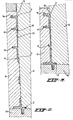
- Fig. 1 is a vertical section of a side wall of a plastic container or crate at the zone of the grip. Part of the adjoining side wall is as yet visible in an outer view.
- the plastic container or crate comprises upright side walls 3 extending between the reinforced outwardly directed upper edges 1 and a bottom 2.
- the walls or portions thereof are at least at the inner side of the container or crate provided with a step extending into the circumferential direction of the container.
- Two steps referenced 4 are shown in section in fig. 1.
- a similar step 4a is provided near the upper edge of the container or crate, mostly in the form of a rounding to prevent a sharp edge directed towards the interior of the container or crate of being provided at the upper edge of the some.
- step or rounding 4a is known per se.
- the portions above the steps 4, so the portions at the upper edge, are - as seen in the upright direction of the walls - disposed with respect to bottom 2, under an angle differing from the angle of the wall portions beneath those steps and the bottom of the container, for a purpose to be described hereinafter.
- the dot-dash lines 5 in fig. 1 illustrate the supplementary planes. Said planes extend parallel to the plane of bottom 2.
- the wall portion between bottom 2 and the first step 4 is a release portion, that is to say that this portion can be drawn from a mould core without any problems, due to the inclination of the wall on a shrinkage of the injected material. It has been found that the angle of this wall portion with respect to the plane of bottom 2 or the plane as depicted by lines 5, is approximately 90 + 3°.
- the wall portion at the upper edge towards the step disposed therebeneath has a different angle, for example 90 - 3°. The same feature applies to the wall portion between the two steps.
- Wall portions above a lower step in the container wall consequently extend in the upright direction counterwise to wall portions beneath a lower step 4. It will be obvious from the angles as described, that the opposite walls of the container with their portions situated above the lower step 4 converge with respect to one another in a direction towards the upper edge 1 of said container.
- the wall portions between one step 4 and the bottom 2 of the container extend in a "releasing" manner, whilst the wall portions above said step extend in an "anti-releasing" manner.
- the step at the inner side of the container extends in a manner curved or inclined with respect to the plane of the wall, as is depicted by angle a.
- the steps 4 in the walls 3 at the inner side of the container also extend at the outer side of the container and merge into a rib 6 projecting from the wall.
- a container or crate comprising walls or wall portions, as illustrated in fig. 1, is particularly suitable to be manufactured inalower embodiment also, by one and the same mould. The measures as described hereinbefore, therefore apply in particular to containers or crates to be mutually stacked and having different heights but also to containers or crates to be stacked and having other heights.
- Fig. 2 illustrates the same wall section analogous to fig. 1, and provided immediately after having injection-moulded plastic material into a mould.
- the steps 4 are provided in the mould core 9.
- Said mould core 9 have a height such, that a container of fig. 1 can also be produced by means of the former.
- Fig. 2 only illustrates a vertical section of part of the lower portion of the mould core 9.
- an injection-mould with a base plate 10 for forming the bottom of the container said base plate 10, in conjunction with a core 9, forming the inner side of the container, side slides co- operating with said core and being laterally removed from the core after the injection-moulding operation so engaging the side walls, that the manufactured container can be drawn from the core after having drawn core 9 and base plate 10 from one another.
- the mould core 9 is provided, in its circumferential direction, with a plurality of steps 4 extending at distance from one another, the mould division referenced 12, between the core 9 and the top part of the side slides 11 being as a result, always posit ⁇ med above the respective step, for which purpose the slides 11 are adapted.
- One and the same mould core 9 provided with steps therefore comprises a plurality of sets of side slides 11 having mutually differing heights, the height of each set of side slides being adapted to a respective step 4 with the mould division 12 positioned above said step.
- Fig. 3 only illustrates the lower part of the mould core 9 and a side slide 11 the division 12 of which being positoned just above the lower step 4. From this it follows that the mould core is in this case adapted to manufacture a very low container or crate the upper edge 1 of which is positioned relatively near the bottom 2.
- the upper edge 1a is situated at one of the steps 4, obviously the same situation is attained as at step 4a in fig. 1, eliminating the occurence of a sharp edge at the upper edge of the container or crate.
- a filler 15 can be screwed upon the mould core at said opening 13.
- Said filler 15 has a chamfered top side 16 to obtain an inclined edge 17, so also eliminating the presence of a sharp edge caused by the mould division.
Landscapes
- Engineering & Computer Science (AREA)
- Mechanical Engineering (AREA)
- Manufacturing & Machinery (AREA)
- Rigid Containers With Two Or More Constituent Elements (AREA)
- Moulds For Moulding Plastics Or The Like (AREA)
- Injection Moulding Of Plastics Or The Like (AREA)
- Details Of Rigid Or Semi-Rigid Containers (AREA)
- Stackable Containers (AREA)
- Containers Having Bodies Formed In One Piece (AREA)
Priority Applications (1)
| Application Number | Priority Date | Filing Date | Title |
|---|---|---|---|
| AT83200971T ATE31276T1 (de) | 1982-07-02 | 1983-06-29 | Kunststoffbehaelter, spritzguss, matrize und verfahren zu ihrer herstellung. |
Applications Claiming Priority (2)
| Application Number | Priority Date | Filing Date | Title |
|---|---|---|---|
| NL8202669A NL8202669A (nl) | 1982-07-02 | 1982-07-02 | Kunststofbak alsmede spuitgietmatrijs en werkwijze voor het vervaardigen van deze kunststofbak. |
| NL8202669 | 1982-07-02 |
Publications (2)
| Publication Number | Publication Date |
|---|---|
| EP0100567A1 true EP0100567A1 (fr) | 1984-02-15 |
| EP0100567B1 EP0100567B1 (fr) | 1987-12-09 |
Family
ID=19839963
Family Applications (1)
| Application Number | Title | Priority Date | Filing Date |
|---|---|---|---|
| EP83200971A Expired EP0100567B1 (fr) | 1982-07-02 | 1983-06-29 | Récipient en matière plastique, moule à injection et procédé de fabrication de ce récipient |
Country Status (4)
| Country | Link |
|---|---|
| EP (1) | EP0100567B1 (fr) |
| AT (1) | ATE31276T1 (fr) |
| DE (1) | DE3374854D1 (fr) |
| NL (1) | NL8202669A (fr) |
Cited By (1)
| Publication number | Priority date | Publication date | Assignee | Title |
|---|---|---|---|---|
| WO1989012005A1 (fr) * | 1988-06-09 | 1989-12-14 | Robert Bosch Gmbh | Recipient empilable pour magasins |
Citations (5)
| Publication number | Priority date | Publication date | Assignee | Title |
|---|---|---|---|---|
| US2843291A (en) * | 1956-03-12 | 1958-07-15 | Stopps Alfred Leslie | Bin |
| FR2135329A1 (fr) * | 1971-05-05 | 1972-12-15 | Ind Onderneming | |
| FR2235058A1 (en) * | 1973-06-28 | 1975-01-24 | Wavin Bv | Plastic trays, stackable on top of each other - rigid construction to prevent sagging from one tray into the other |
| FR2409212A1 (fr) * | 1977-11-18 | 1979-06-15 | Sibec Sarl | Boite pour appats vivants |
| EP0028869A1 (fr) * | 1979-11-12 | 1981-05-20 | Wavin B.V. | Caisse ou plateau en matière plastique et moule à injection pour la fabrication de la caisse ou du plateau en matière plastique |
-
1982
- 1982-07-02 NL NL8202669A patent/NL8202669A/nl not_active Application Discontinuation
-
1983
- 1983-06-29 AT AT83200971T patent/ATE31276T1/de active
- 1983-06-29 DE DE8383200971T patent/DE3374854D1/de not_active Expired
- 1983-06-29 EP EP83200971A patent/EP0100567B1/fr not_active Expired
Patent Citations (5)
| Publication number | Priority date | Publication date | Assignee | Title |
|---|---|---|---|---|
| US2843291A (en) * | 1956-03-12 | 1958-07-15 | Stopps Alfred Leslie | Bin |
| FR2135329A1 (fr) * | 1971-05-05 | 1972-12-15 | Ind Onderneming | |
| FR2235058A1 (en) * | 1973-06-28 | 1975-01-24 | Wavin Bv | Plastic trays, stackable on top of each other - rigid construction to prevent sagging from one tray into the other |
| FR2409212A1 (fr) * | 1977-11-18 | 1979-06-15 | Sibec Sarl | Boite pour appats vivants |
| EP0028869A1 (fr) * | 1979-11-12 | 1981-05-20 | Wavin B.V. | Caisse ou plateau en matière plastique et moule à injection pour la fabrication de la caisse ou du plateau en matière plastique |
Cited By (1)
| Publication number | Priority date | Publication date | Assignee | Title |
|---|---|---|---|---|
| WO1989012005A1 (fr) * | 1988-06-09 | 1989-12-14 | Robert Bosch Gmbh | Recipient empilable pour magasins |
Also Published As
| Publication number | Publication date |
|---|---|
| DE3374854D1 (en) | 1988-01-21 |
| NL8202669A (nl) | 1984-02-01 |
| EP0100567B1 (fr) | 1987-12-09 |
| ATE31276T1 (de) | 1987-12-15 |
Similar Documents
| Publication | Publication Date | Title |
|---|---|---|
| US3448888A (en) | Denestable container cover | |
| US3632016A (en) | Cover interlocking preventive device | |
| US4076123A (en) | Disposable plastic lid | |
| US3391815A (en) | Bottle case | |
| US5592766A (en) | Container lid/closure with printed closure insert | |
| US3321104A (en) | Coin fed lid | |
| US3353707A (en) | Nestable container | |
| US5791509A (en) | Uniform stacking cup lid | |
| US6685049B1 (en) | Thin wall closure for use with a container | |
| US4905833A (en) | Nestable and stackable container | |
| US4102453A (en) | Nesting and stacking container | |
| US6059114A (en) | Container | |
| US3664272A (en) | Stackable pallet constructions | |
| US3419182A (en) | Reinforced milk crate | |
| US3390808A (en) | Milk crate | |
| CA2655462C (fr) | Caisse a claire-voie pouvant etre empilee | |
| US3220631A (en) | Display tray | |
| US4379508A (en) | Nesting tray with stacking keyed interlock | |
| US3586205A (en) | Transport container from plastics with cover | |
| US4364476A (en) | Plastic lid with stacking separation means | |
| US3341060A (en) | Milk crate | |
| EP0100567B1 (fr) | Récipient en matière plastique, moule à injection et procédé de fabrication de ce récipient | |
| EP3580132B1 (fr) | Récipient en plastique thermoformé | |
| US3445034A (en) | Plastic crate with metal stacking ear | |
| EP0028869B1 (fr) | Caisse ou plateau en matière plastique et moule à injection pour la fabrication de la caisse ou du plateau en matière plastique |
Legal Events
| Date | Code | Title | Description |
|---|---|---|---|
| PUAI | Public reference made under article 153(3) epc to a published international application that has entered the european phase |
Free format text: ORIGINAL CODE: 0009012 |
|
| AK | Designated contracting states |
Designated state(s): AT BE CH DE FR GB IT LI LU NL SE |
|
| 17P | Request for examination filed |
Effective date: 19840808 |
|
| GRAA | (expected) grant |
Free format text: ORIGINAL CODE: 0009210 |
|
| AK | Designated contracting states |
Kind code of ref document: B1 Designated state(s): AT BE CH DE FR GB IT LI LU NL SE |
|
| PG25 | Lapsed in a contracting state [announced via postgrant information from national office to epo] |
Ref country code: NL Effective date: 19871209 Ref country code: LI Effective date: 19871209 Ref country code: IT Free format text: LAPSE BECAUSE OF FAILURE TO SUBMIT A TRANSLATION OF THE DESCRIPTION OR TO PAY THE FEE WITHIN THE PRESCRIBED TIME-LIMIT;WARNING: LAPSES OF ITALIAN PATENTS WITH EFFECTIVE DATE BEFORE 2007 MAY HAVE OCCURRED AT ANY TIME BEFORE 2007. THE CORRECT EFFECTIVE DATE MAY BE DIFFERENT FROM THE ONE RECORDED. Effective date: 19871209 Ref country code: CH Effective date: 19871209 Ref country code: BE Effective date: 19871209 Ref country code: AT Effective date: 19871209 |
|
| REF | Corresponds to: |
Ref document number: 31276 Country of ref document: AT Date of ref document: 19871215 Kind code of ref document: T |
|
| PG25 | Lapsed in a contracting state [announced via postgrant information from national office to epo] |
Ref country code: SE Effective date: 19871231 |
|
| REF | Corresponds to: |
Ref document number: 3374854 Country of ref document: DE Date of ref document: 19880121 |
|
| ET | Fr: translation filed | ||
| REG | Reference to a national code |
Ref country code: CH Ref legal event code: PL |
|
| NLV1 | Nl: lapsed or annulled due to failure to fulfill the requirements of art. 29p and 29m of the patents act | ||
| PG25 | Lapsed in a contracting state [announced via postgrant information from national office to epo] |
Ref country code: GB Effective date: 19880629 |
|
| PG25 | Lapsed in a contracting state [announced via postgrant information from national office to epo] |
Ref country code: LU Free format text: LAPSE BECAUSE OF NON-PAYMENT OF DUE FEES Effective date: 19880630 |
|
| PLBE | No opposition filed within time limit |
Free format text: ORIGINAL CODE: 0009261 |
|
| STAA | Information on the status of an ep patent application or granted ep patent |
Free format text: STATUS: NO OPPOSITION FILED WITHIN TIME LIMIT |
|
| 26N | No opposition filed | ||
| GBPC | Gb: european patent ceased through non-payment of renewal fee | ||
| PG25 | Lapsed in a contracting state [announced via postgrant information from national office to epo] |
Ref country code: FR Free format text: LAPSE BECAUSE OF NON-PAYMENT OF DUE FEES Effective date: 19890228 |
|
| PG25 | Lapsed in a contracting state [announced via postgrant information from national office to epo] |
Ref country code: DE Effective date: 19890301 |
|
| REG | Reference to a national code |
Ref country code: FR Ref legal event code: ST |