EP0100576A1 - Méthode pour analyser la tension produite par induction dans la bobine d'excitation d'un moteur pas-à-pas - Google Patents
Méthode pour analyser la tension produite par induction dans la bobine d'excitation d'un moteur pas-à-pas Download PDFInfo
- Publication number
- EP0100576A1 EP0100576A1 EP83201107A EP83201107A EP0100576A1 EP 0100576 A1 EP0100576 A1 EP 0100576A1 EP 83201107 A EP83201107 A EP 83201107A EP 83201107 A EP83201107 A EP 83201107A EP 0100576 A1 EP0100576 A1 EP 0100576A1
- Authority
- EP
- European Patent Office
- Prior art keywords
- polarity
- voltage
- exciter coil
- current
- period
- Prior art date
- Legal status (The legal status is an assumption and is not a legal conclusion. Google has not performed a legal analysis and makes no representation as to the accuracy of the status listed.)
- Granted
Links
Images


Classifications
-
- G—PHYSICS
- G04—HOROLOGY
- G04C—ELECTROMECHANICAL CLOCKS OR WATCHES
- G04C3/00—Electromechanical clocks or watches independent of other time-pieces and in which the movement is maintained by electric means
- G04C3/14—Electromechanical clocks or watches independent of other time-pieces and in which the movement is maintained by electric means incorporating a stepping motor
- G04C3/143—Means to reduce power consumption by reducing pulse width or amplitude and related problems, e.g. detection of unwanted or missing step
-
- H—ELECTRICITY
- H02—GENERATION; CONVERSION OR DISTRIBUTION OF ELECTRIC POWER
- H02P—CONTROL OR REGULATION OF ELECTRIC MOTORS, ELECTRIC GENERATORS OR DYNAMO-ELECTRIC CONVERTERS; CONTROLLING TRANSFORMERS, REACTORS OR CHOKE COILS
- H02P8/00—Arrangements for controlling dynamo-electric motors rotating step by step
- H02P8/12—Control or stabilisation of current
Definitions
- the invention relates to a method of analysing the voltage induced in an exciter coil of a stepping motor in detection periods which occur after energization.
- the invention also relates to a circuit for carrying out the method.
- Stepping motors are inter alia employed in watches. For this purpose it is important that the motor behaviour can be measured, for example, in order to minimize the power consumption of the stepping motor.
- This article describes how the sum of the voltage across the internal resistance of the motor, which voltage is constant as a result of the current control, and the induction voltage can be derived from the relative time interval in which the motor is connected to the battery.
- the self-inductance of the motor then does not play part as a result of the constant-current control.
- By analysing the variation of this induction voltage it is then possible to obtain various data as regards the motor behaviour. For example, it is possible to determine the instant at which the motor has made a step and subsequently the current pulse may be interrupted in order to limit the power consumption.
- the method according to the invention is characterized in that in said detection periods the exciter coil is loaded by a low impedance so that the induction voltage can produce an induction current, the polarity of the current in the exciter coil is detected at periodic instants during said detection period, in accordance with the detected polarity the exciter coil is energized with a voltage of such a polarity that the instantaneous current in the exciter coil is counteracted, and the pattern of consecutive energizations during said detection periods is analysed.
- the self-inductance of -aid coil is "charged” or “discharged” by means of positive and negative current pulses respectively as a result of the voltage drive and it is achieved that - if possible - the current in the coil (the "charge” of the self-inductance) is maintained substantially equal to zero.
- the pattern of positive and negative energizations is representative of the variation of the induction voltage, so that after conversion of this pattern into a sequence of binary units the induction voltage can be analysed by purely logic means.
- the exciter coil is energized with a periodic pattern of voltage pulses of constant duration, whose polarity is controlled as a function of the detected polarity of the current in the exciter coil.
- the method in accordance with the invention may further be characterized in that the ratio of the number of voltage pulses of one polarity to the number of voltage pulses of the other polarity over a specific period is determined.
- This method in accordance with the invention may further be characterized in that the voltage pulses have a specific curation which is a fraction of the length of the period with which they recur.
- the method in accordance with the invention may be further characterized in that it is detected whether series of more than a predetermined number of consecutive pulses of the same polarity occur.
- said series When said series are sufficiently long they correspond to the periods in which said "saturations" occur. Said series consequently correspond to the periods in which the absolute value of the induction voltage is greater than said fraction of the voltage of the voltage pulses, so that it is detected whether the induction voltage has exceeded a specific level. This may be utilized in order to detect whether the stepping motor has made a step.
- the method in accordance with the invention may further be characterized in that it is detected wh d her a second series of at least a first predetermined number of consecutive pulses of a polarity which, relative to the exciter coil, is opposite to the polarity of the voltage across the exciter coil during energization occurs after a first series of at least a second predetermined number of consecutive pulses of an opposite polarity has occurred.
- This last-mentioned method may be further characterized in that each detection period is terminated at least a predetermined time interval after the detection of the first period.
- a circuit for carrying out the method may be characterized in that the circuit comprises a comparator for determining the polarity of the current in the exciter coil of the stepping motor, a command-signal generator for generating a signal in conformity with the detected polarity of said current, a commutation circuit for connecting the exciter coil of the stepping motor to a voltage source under command of said signal, in such a way that the polarity of the resulting current variation in the exciter coil is orposite to the polarity determined by the compara- tive and a logic gate circuit for analysing the consecutive polarities of said current variations.
- This circuit may further be characterized in that the logic gate circuit receives said signal as an input signal.
- This circuit may further be characterized in that the logic gate circuit comprises counting means for detecting whether at least a first number of consecutive signals corresponding to a first polarity of said current, which first polarity is opposite to the polarity of the current in the exciter coil during the preceding drive, occurs after a second number of consecutive signals corresponding to a second polarity, opposite to the first polarity, has occurred.
- the object of the invention to provide a method of the type mentioned in the opening paragraph which makes it possible to detect whether the motor has made a step in a manner which is highly independent of the motor parameters and to provide a circuit for carrying out this method.
- the method is characterized in that, for establishing whether the stepping motor has made a step as a result of said energization, it is detected whether the induction voltage has been negative to more than a predetermined extent for at least a second period of predetermined duration after said induction voltage has been positive to more than a predetermined extent for at least a first period of predetermined duration.
- the method may further be characterized in that in said detection periods the exciter coil is loaded by a low impedance so that the induction voltage can produce an induction current, the polarity of the current in the exciter coil is detected at periodic instants during said detection periods in accordance with the detected polarity the exciter coil is energized with a voltage of such a polarity that the instantaneous current in the exciter coil is counteracted, and the pattern of consecutive energizations during said detection periods is analysed.
- the circuit for carrying out the method may be characterized in that the circuit comprises comparison means for comparing the induction voltage with the voltage of a voltage source and a detection circuit for detecting whether the induction voltage has been negative to more than a predetermined extent for at least the second period of predetermined duration after said induction voltage has been p ⁇ itive to more than a predetermined extent for at least the first period of predetermined duration.
- This circuit may further be characterized in that the comparison means comprise a comparator for determining the polarity of the current in the exciter coil of the stepping motor, a command signal generator for generating a signal in conformity with the detected polarity of said current, a commutation circuit for connecting the exciter coil of the stepping motor to the voltage source under command of said signal, in such a way that the polarity of the resulting current variation in the exciter coil is opposite to the polarity determined by the comparator, and the detection circuit is a logic gate circuitfor analysing the consecutive polarities of said current variations.
- the comparison means comprise a comparator for determining the polarity of the current in the exciter coil of the stepping motor, a command signal generator for generating a signal in conformity with the detected polarity of said current, a commutation circuit for connecting the exciter coil of the stepping motor to the voltage source under command of said signal, in such a way that the polarity of the resulting current variation in the exc
- FIG. 1 shows the basic diagram of an induction-voltage detection circuit in which the method in accordance with the invention can be cited.
- the operating principle is to maintain the current in the motor at a value equal to zero.
- the motor is represented by the self-inductance 1 of value L, the resistor 2 of value Rand a voltage source 3 supplying an induction voltage U i .
- the motor is connected to the output of a power amplifier 4 via a resistor 5 of comparatively low resistance.
- the resistor 5 is arranged between the inputs of a comparator 6 which supplies a logic signal which is a function of the polarity of the voltage across the resistor 5 and, consequently, is a function of the polarity of the current I through the resistor 5 and the motor.
- the output of the comparator 6 is connected to the input d of a flip-flop 7, whose clock input c receives a signal f having a frequency of a few kHz.
- the output Q of the flip-flop 7 is connected to the input of the power amplifier 4 which can supply either a voltage +V or a voltage -V to the motor.
- the voltage on the output of amplifier 4 is a signal comprising a number n + of periods in which the voltage is equal to +V and a number n - of periods during which the voltage is -V.
- the length ⁇ t of these periods is defined by the clock signal f .
- the voltage U c on the output of amplifier 4 complies with : where ⁇ I is the variation of the current I during the period ⁇ t.
- this logic signal is representative of the induction voltage U i so that it is possible to analyse this induction voltage U. by logic means.
- the parameter represents the ratio of the induction voltage U i to the supply voltage V.
- U i may become comparatively small, this parameter may also become small and the definition of the system may deteriorate. Therefore, in order to increase this definition, the voltage applied to the motor may be reduced. This can be achieved very simply by applying the voltages +V and -V only for a fraction 1/P of the period ⁇ t.
- the expression for the induction voltage U . then becomes:
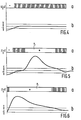
- Figures 2a to 6a show the waveforms of the logic signal on the output of flip-flop 7 for various typical situations and Figures 2b to 6b show the corresponding wave forms of the induction voltage.
- the parameter P has been selected to equal 8, so that the system becomes saturated (the factor is maximum or a minimum and the output of flip-flop 7 is constantly “0" or "1") when the induction voltage U i exceeds the value +V/8 or -V/8.
- Figures a these ranges are designated “+” (U. positive) and "-" (U i negative), whilst the intermediate ranges, where the output of flip-flop 7 changes between 1 and 0 and the induction voltage U i has a value between +V/8 and -V/8, are represented by vertical hatching.
- the logic signal comprises a "+" period (P1) followed by a "-" period (P2) and an intermediate period where the logic signal alternates between "0" and "1".
- FIG. 7 shows a motor control circuit which is equipped with an induction-voltage detector in accordance with the invention.
- the circuit comprises an oscillator 10 and a frequency divider 11 which supplies signals of the frequencies 8 kHz, 2 kHz, 512 Hz, 64 Hz, 16 Hz, 1 Hz and 0.5 Hz.
- the 1-Hz output is connected to the clock input c of a flip-flop 13 whose input d is "1" and whose reset input 5 is connected to the 64-Hz output of the divider.
- the flip-flop 13 produces a 7.8 ms pulse on its Q-output every second.
- This Q-output is connected to an input of an OR-gate 14 whose output is connected to the inputs a of the AND-gates 15 and 16, the outputs of AND-gates 15 and 16 are connected to inputs a of OR-gates 17 and 18.
- Input b of gate 15 is connected to the O.5-Hz output of the divider 11, which output is connected to the input b of gate 16 via an inverter 19.
- the outputs of gates 17 and 18 are connected to the terminals of the motor coil via power amplifiers 20 and 21, each having a so-called "three-state" output (high, low and floating). Consequently, the gates 17 and 18 transfer the output pulses of flip-flop 13 (7.8 msecs. every second) to the amplifiers 20 and 21 alternately, so that for 7 msecs. of every second the motor coil receives a voltage pulse whose polarity changes every second.
- each drive pulse (7.8 msecs.) the Q output of flip-flop 13 goes to 1.
- This output is connected to the clock input of a flip-flop 22, whose input d is connected to "1" and whose reset input is connected to the 512-Hz output of the divider 11.
- the flip-flop 22 supplies an 1-msec. pulse.
- the Q-output of flip-flop 22 is connected to an enable input of amplifiers 20 and 21, so that during this 1 msec. the outputs of the amplifiers 20 and 21 will have a high impedance. This high impedance reduces the time constant L/R of the motor-coil circuit so that the current in the coil as a result of the drive pulse can rapidly decrease to zero.
- the Q-output of flip-flop 24 is connected to the input a of AND-gates 25 and 26, whose outputs are connected to the inputs b of OR-gates 17 and 18 and whose inputs b are connected to the Q and Q-outputs of a flip-flop 27, which has the same function as the flip-flop 7 in the circuit arrangement shown in Figure 1.
- the input d of flip-flop 27 is connected to an output of a voltage- comparator circuit 28, whose inputs are connected to the terminals of a motor coil 37. Although the internal resistance R of the motor coil is negligible, the polarity of the current through the coil can be measured if the internal resistance of the outputs of amplifiers 20 and 21 is sufficiently high.
- the clock input of flip-flop 27 is connected to the output of the inverter 29, whose input is connected to the 2-kHz output of the divider 11. Depending on the state of flip-flop 27 the pulses supplied by the flip-flop 24 will appear on the output of amplifier 20 via gates 17 and 25 or on the output of the amplifier 21 via gates 18 and 26.
- the motor receives 2-kHz pulses of a polarity which is such that the current through the coil tends to become zero.
- the output signal of flip-flop 27 is analysed.
- This output signal is applied to one input of an exclusive-OR-gate 30 whose other input is connected to the output of inverter 19 on which the 0.5-Hz pulses appear.
- This gate 30 inverts the output signal of flip-flop 27 for half of every two seconds, whichis necessary because the polarity of the induction voltage is inverted every second as a result of the polarity reversal of the drive pulse every second.
- the output signal of gate 30 is applied to input a of an exclusive OR-gate 31 whose output is connected to the input of an OR-gate 32.
- the output of gate 32 is connected to the reset input of a scale-of-4 counter 33.
- the second input of gate 32 is connected to the Q-output of flip-flop 23 and to the reset input r of a flip-flop 34 the set input S of a flip-flop 35, and the clock input c of a flip-flop 36.
- the clock input c of the counter 33 is connected to the 2-kHz output of the divider 11 and output Q4 of the counter is connected to the clock inputs c of the flip-flops 34 and 35.
- the Q-output of flip-flop 34 is connected to input d of flip-flop 35 and input b of gate 31, whilst the Q-output of flip-flop 35 is connected to the input d of flip-flop 36.
- the reset input r of flip-flop 36 is connected to the 64-Hz output of the divider 11 and the Q-output of this flip-flop 36 is connected to a second input of the OR-gate 14.
- flip-flop 35 If only the period P1 or neither the period P1 nor the period P2 has been detected, the Q-output of flip-flop 35 remains at "1". As a result of this, the output of flip-flop 36 goes to "1" after 31 msecs, because the Q-output of flip-flop 23 then goes to 1. As flip-flop 36 is reset by the 64-Hz signal the Q-output of flip-flop 36 remains at "1" for approximately 8 msecs. Thus, if the requirements are not met, which corresponds to the situation in which the motor has not made a step, flip-flop 36 generates a new 8 msec. pulse 31 msecs. after the beginning of the drive pulse, which new pulse is applied to the motor via gate 14, gate 15 or 16, gate 17 or 18, and the amplifier 20 or 21 in order to ensure tha; a step is even now actually made.
- the invention is not limited to the embodiment shown.
- the described analysis of the induction voltage may be used for adapting the energy of the drive pulse to the motor load.
- the criterion described in the foregoing may also be used for detecting whether the motor has made a step in the case of, for example, an analogue circuit which compares the induction voltage directly with a reference level in stead of using the described method for analysing the induction voltage.
Landscapes
- Physics & Mathematics (AREA)
- General Physics & Mathematics (AREA)
- Engineering & Computer Science (AREA)
- Power Engineering (AREA)
- Control Of Stepping Motors (AREA)
- Electromechanical Clocks (AREA)
Applications Claiming Priority (2)
| Application Number | Priority Date | Filing Date | Title |
|---|---|---|---|
| NL8203094 | 1982-08-04 | ||
| NL8203094A NL8203094A (nl) | 1982-08-04 | 1982-08-04 | Werkwijze voor het analyseren van de in een bekrachtigingsspoel van een stappenmotor geinduceerde spanning. |
Publications (2)
| Publication Number | Publication Date |
|---|---|
| EP0100576A1 true EP0100576A1 (fr) | 1984-02-15 |
| EP0100576B1 EP0100576B1 (fr) | 1987-09-16 |
Family
ID=19840107
Family Applications (1)
| Application Number | Title | Priority Date | Filing Date |
|---|---|---|---|
| EP83201107A Expired EP0100576B1 (fr) | 1982-08-04 | 1983-07-28 | Méthode pour analyser la tension produite par induction dans la bobine d'excitation d'un moteur pas-à-pas |
Country Status (7)
| Country | Link |
|---|---|
| US (1) | US4800334A (fr) |
| EP (1) | EP0100576B1 (fr) |
| JP (1) | JPH0669318B2 (fr) |
| CA (1) | CA1220817A (fr) |
| DE (1) | DE3373723D1 (fr) |
| HK (1) | HK34789A (fr) |
| NL (1) | NL8203094A (fr) |
Cited By (1)
| Publication number | Priority date | Publication date | Assignee | Title |
|---|---|---|---|---|
| CN111769768A (zh) * | 2020-05-29 | 2020-10-13 | 广东乐芯智能科技有限公司 | 一种手表步进电机驱动补偿方法 |
Families Citing this family (2)
| Publication number | Priority date | Publication date | Assignee | Title |
|---|---|---|---|---|
| US6573727B2 (en) * | 2001-01-25 | 2003-06-03 | General Electric Company | Method and apparatus for evaluation of insulation in variable speed motors |
| JP2004170314A (ja) * | 2002-11-21 | 2004-06-17 | Advantest Corp | 試験装置、試験方法、及び電流測定器 |
Citations (7)
| Publication number | Priority date | Publication date | Assignee | Title |
|---|---|---|---|---|
| US3586953A (en) * | 1967-09-22 | 1971-06-22 | Fairchild Camera Instr Co | Stepper motor control system |
| US3842331A (en) * | 1972-12-27 | 1974-10-15 | Ibm | Digital stepping motor control system |
| GB2009464A (en) * | 1977-12-02 | 1979-06-13 | Seiko Instr & Electronics | Stepping motor driven analog timepieces |
| US4192131A (en) * | 1977-01-19 | 1980-03-11 | Kabushiki Kaisha Suwa Seikosha | Step motor control mechanism for electronic timepiece |
| US4209971A (en) * | 1977-04-23 | 1980-07-01 | Kabushiki Kaisha Daini Seikosha | Electronic timepiece |
| GB2070813A (en) * | 1980-02-19 | 1981-09-09 | Berney Sa Jean Claude | Timepiece with a device for the control of a stepping motor |
| GB2076567A (en) * | 1980-05-13 | 1981-12-02 | Citizen Watch Co Ltd | Electronic timepiece |
Family Cites Families (6)
| Publication number | Priority date | Publication date | Assignee | Title |
|---|---|---|---|---|
| FR1210441A (fr) * | 1958-09-27 | 1960-03-08 | Contrôleur de circuits électriques | |
| US3742351A (en) * | 1970-07-17 | 1973-06-26 | Nu Concept Computer Co | Digital test probe with signal latches and conditionable gating |
| JPS5262615A (en) * | 1975-11-20 | 1977-05-24 | Fujitsu Fanuc Ltd | Electric pulse motor drive system |
| JPS5475520A (en) * | 1977-11-30 | 1979-06-16 | Seiko Instr & Electronics Ltd | Operation detecting circuit of step motor |
| FR2459579A1 (fr) * | 1979-06-21 | 1981-01-09 | Suisse Horlogerie | Detecteur d'avance d'un moteur pas a pas |
| FR2461399A1 (fr) * | 1979-07-09 | 1981-01-30 | Suisse Horlogerie | Detecteur de position d'un moteur pas a pas |
-
1982
- 1982-08-04 NL NL8203094A patent/NL8203094A/nl not_active Application Discontinuation
-
1983
- 1983-07-28 CA CA000433439A patent/CA1220817A/fr not_active Expired
- 1983-07-28 EP EP83201107A patent/EP0100576B1/fr not_active Expired
- 1983-07-28 DE DE8383201107T patent/DE3373723D1/de not_active Expired
- 1983-08-01 JP JP58140952A patent/JPH0669318B2/ja not_active Expired - Lifetime
-
1986
- 1986-08-27 US US06/900,861 patent/US4800334A/en not_active Expired - Lifetime
-
1989
- 1989-04-27 HK HK347/89A patent/HK34789A/en not_active IP Right Cessation
Patent Citations (8)
| Publication number | Priority date | Publication date | Assignee | Title |
|---|---|---|---|---|
| US3586953A (en) * | 1967-09-22 | 1971-06-22 | Fairchild Camera Instr Co | Stepper motor control system |
| US3842331A (en) * | 1972-12-27 | 1974-10-15 | Ibm | Digital stepping motor control system |
| US4192131A (en) * | 1977-01-19 | 1980-03-11 | Kabushiki Kaisha Suwa Seikosha | Step motor control mechanism for electronic timepiece |
| US4209971A (en) * | 1977-04-23 | 1980-07-01 | Kabushiki Kaisha Daini Seikosha | Electronic timepiece |
| GB2009464A (en) * | 1977-12-02 | 1979-06-13 | Seiko Instr & Electronics | Stepping motor driven analog timepieces |
| US4326278A (en) * | 1977-12-02 | 1982-04-20 | Kabushiki Kaisha Daini Seikosha | Electronic timepiece |
| GB2070813A (en) * | 1980-02-19 | 1981-09-09 | Berney Sa Jean Claude | Timepiece with a device for the control of a stepping motor |
| GB2076567A (en) * | 1980-05-13 | 1981-12-02 | Citizen Watch Co Ltd | Electronic timepiece |
Non-Patent Citations (2)
| Title |
|---|
| PATENTS ABSTRACTS OF JAPAN, vol. 5, no. 51 (E-51)[723], 10th April 1981, page 58 E 51 & JP-A-56 001799 (DAINI SEIKOSHA K.K.) 09-01-1981 * |
| SOCIETE SUISSE DE CHRONOMETRIE, 56th Congress, Neuchatel, 23rd-24th October 1981, Communication no. 27, pages 185-188 * |
Cited By (1)
| Publication number | Priority date | Publication date | Assignee | Title |
|---|---|---|---|---|
| CN111769768A (zh) * | 2020-05-29 | 2020-10-13 | 广东乐芯智能科技有限公司 | 一种手表步进电机驱动补偿方法 |
Also Published As
| Publication number | Publication date |
|---|---|
| CA1220817A (fr) | 1987-04-21 |
| NL8203094A (nl) | 1984-03-01 |
| DE3373723D1 (en) | 1987-10-22 |
| EP0100576B1 (fr) | 1987-09-16 |
| JPS5947998A (ja) | 1984-03-17 |
| US4800334A (en) | 1989-01-24 |
| HK34789A (en) | 1989-05-05 |
| JPH0669318B2 (ja) | 1994-08-31 |
Similar Documents
| Publication | Publication Date | Title |
|---|---|---|
| US5038329A (en) | Step motor control mechanism for electronic timepiece | |
| US4460282A (en) | Timepiece stepping motor drive circuit with stepping failure compensation | |
| KR910006817A (ko) | 교류기의 출력 전력 제어용 조절기 | |
| US4433401A (en) | Electronic timepiece having a stepping motor and driving circuit compensated for power source variations | |
| EP0432971A1 (fr) | Circuit de commande pour moteur à ultrasons | |
| US4467256A (en) | Method and device for controlling a stepping motor of a timepiece | |
| GB2076566A (en) | Electronic timepiece | |
| EP0100576A1 (fr) | Méthode pour analyser la tension produite par induction dans la bobine d'excitation d'un moteur pas-à-pas | |
| US5001406A (en) | Brushless DC motor speed control via power supply voltage level control | |
| US5774426A (en) | Method and device for feeding a single-phase stepping motor | |
| GB1598387A (en) | Electronic watches | |
| CA1115812A (fr) | Circuit digital a retard vital | |
| EP0381217A2 (fr) | Circuits de commutation pour détecter le niveau des signaux | |
| EP0222423B1 (fr) | Système pour commander la vitesse d'un moteur électrique | |
| EP0328109A1 (fr) | Générateur haute tension | |
| JPS60204299A (ja) | ステツピングモータの駆動装置 | |
| JPS63129863A (ja) | スイツチング電源装置 | |
| JPS6324577B2 (fr) | ||
| SU1172014A1 (ru) | Частотно-импульсный преобразователь | |
| JPS57152970A (en) | Heat-sensitive recorder | |
| SU928593A1 (ru) | Способ управлени однофазным шаговым двигателем и устройство дл его осуществлени | |
| JP2658126B2 (ja) | 入力周波数の発生装置 | |
| KR940005143B1 (ko) | 디지탈 서보의 pwm 구동장치 | |
| SU1644108A1 (ru) | Импульсный регул тор тока дл активно-индуктивной нагрузки | |
| JP2869536B2 (ja) | 型彫放電加工機用電源装置および放電加工方法 |
Legal Events
| Date | Code | Title | Description |
|---|---|---|---|
| PUAI | Public reference made under article 153(3) epc to a published international application that has entered the european phase |
Free format text: ORIGINAL CODE: 0009012 |
|
| AK | Designated contracting states |
Designated state(s): CH DE FR GB LI |
|
| 17P | Request for examination filed |
Effective date: 19840224 |
|
| GRAA | (expected) grant |
Free format text: ORIGINAL CODE: 0009210 |
|
| AK | Designated contracting states |
Kind code of ref document: B1 Designated state(s): CH DE FR GB LI |
|
| REF | Corresponds to: |
Ref document number: 3373723 Country of ref document: DE Date of ref document: 19871022 |
|
| ET | Fr: translation filed | ||
| PLBE | No opposition filed within time limit |
Free format text: ORIGINAL CODE: 0009261 |
|
| STAA | Information on the status of an ep patent application or granted ep patent |
Free format text: STATUS: NO OPPOSITION FILED WITHIN TIME LIMIT |
|
| 26N | No opposition filed | ||
| REG | Reference to a national code |
Ref country code: CH Ref legal event code: PFA Free format text: PHILIPS ELECTRONICS N.V. |
|
| REG | Reference to a national code |
Ref country code: FR Ref legal event code: CD |
|
| REG | Reference to a national code |
Ref country code: CH Ref legal event code: PFA Free format text: PHILIPS ELECTRONICS N.V. TRANSFER- KONINKLIJKE PHILIPS ELECTRONICS N.V. |
|
| REG | Reference to a national code |
Ref country code: FR Ref legal event code: CD |
|
| PGFP | Annual fee paid to national office [announced via postgrant information from national office to epo] |
Ref country code: DE Payment date: 19990826 Year of fee payment: 17 |
|
| PGFP | Annual fee paid to national office [announced via postgrant information from national office to epo] |
Ref country code: CH Payment date: 20001006 Year of fee payment: 18 |
|
| PG25 | Lapsed in a contracting state [announced via postgrant information from national office to epo] |
Ref country code: DE Free format text: LAPSE BECAUSE OF NON-PAYMENT OF DUE FEES Effective date: 20010501 |
|
| PGFP | Annual fee paid to national office [announced via postgrant information from national office to epo] |
Ref country code: FR Payment date: 20010725 Year of fee payment: 19 |
|
| PG25 | Lapsed in a contracting state [announced via postgrant information from national office to epo] |
Ref country code: LI Free format text: LAPSE BECAUSE OF THE APPLICANT RENOUNCES Effective date: 20010731 Ref country code: CH Free format text: LAPSE BECAUSE OF THE APPLICANT RENOUNCES Effective date: 20010731 |
|
| PGFP | Annual fee paid to national office [announced via postgrant information from national office to epo] |
Ref country code: GB Payment date: 20010731 Year of fee payment: 19 |
|
| REG | Reference to a national code |
Ref country code: GB Ref legal event code: IF02 |
|
| REG | Reference to a national code |
Ref country code: CH Ref legal event code: PL |
|
| PG25 | Lapsed in a contracting state [announced via postgrant information from national office to epo] |
Ref country code: GB Free format text: LAPSE BECAUSE OF NON-PAYMENT OF DUE FEES Effective date: 20020728 |
|
| GBPC | Gb: european patent ceased through non-payment of renewal fee |
Effective date: 20020728 |
|
| PG25 | Lapsed in a contracting state [announced via postgrant information from national office to epo] |
Ref country code: FR Free format text: LAPSE BECAUSE OF NON-PAYMENT OF DUE FEES Effective date: 20030331 |
|
| REG | Reference to a national code |
Ref country code: FR Ref legal event code: ST |