EP0100577A1 - Socket retainer - Google Patents
Socket retainer Download PDFInfo
- Publication number
- EP0100577A1 EP0100577A1 EP83201118A EP83201118A EP0100577A1 EP 0100577 A1 EP0100577 A1 EP 0100577A1 EP 83201118 A EP83201118 A EP 83201118A EP 83201118 A EP83201118 A EP 83201118A EP 0100577 A1 EP0100577 A1 EP 0100577A1
- Authority
- EP
- European Patent Office
- Prior art keywords
- ring
- socket
- fingers
- pin
- hole
- Prior art date
- Legal status (The legal status is an assumption and is not a legal conclusion. Google has not performed a legal analysis and makes no representation as to the accuracy of the status listed.)
- Ceased
Links
Images

Classifications
-
- B—PERFORMING OPERATIONS; TRANSPORTING
- B25—HAND TOOLS; PORTABLE POWER-DRIVEN TOOLS; MANIPULATORS
- B25B—TOOLS OR BENCH DEVICES NOT OTHERWISE PROVIDED FOR, FOR FASTENING, CONNECTING, DISENGAGING, OR HOLDING
- B25B23/00—Details of, or accessories for, spanners, wrenches, screwdrivers
- B25B23/0007—Connections or joints between tool parts
- B25B23/0035—Connection means between socket or screwdriver bit and tool
-
- B—PERFORMING OPERATIONS; TRANSPORTING
- B25—HAND TOOLS; PORTABLE POWER-DRIVEN TOOLS; MANIPULATORS
- B25G—HANDLES FOR HAND IMPLEMENTS
- B25G3/00—Attaching handles to the implements
- B25G3/02—Socket, tang, or like fixings
- B25G3/12—Locking and securing devices
- B25G3/26—Locking and securing devices comprising nails, screws, bolts, or pins traversing or entering the socket
-
- F—MECHANICAL ENGINEERING; LIGHTING; HEATING; WEAPONS; BLASTING
- F16—ENGINEERING ELEMENTS AND UNITS; GENERAL MEASURES FOR PRODUCING AND MAINTAINING EFFECTIVE FUNCTIONING OF MACHINES OR INSTALLATIONS; THERMAL INSULATION IN GENERAL
- F16B—DEVICES FOR FASTENING OR SECURING CONSTRUCTIONAL ELEMENTS OR MACHINE PARTS TOGETHER, e.g. NAILS, BOLTS, CIRCLIPS, CLAMPS, CLIPS OR WEDGES; JOINTS OR JOINTING
- F16B2200/00—Constructional details of connections not covered for in other groups of this subclass
- F16B2200/69—Redundant disconnection blocking means
-
- Y—GENERAL TAGGING OF NEW TECHNOLOGICAL DEVELOPMENTS; GENERAL TAGGING OF CROSS-SECTIONAL TECHNOLOGIES SPANNING OVER SEVERAL SECTIONS OF THE IPC; TECHNICAL SUBJECTS COVERED BY FORMER USPC CROSS-REFERENCE ART COLLECTIONS [XRACs] AND DIGESTS
- Y10—TECHNICAL SUBJECTS COVERED BY FORMER USPC
- Y10T—TECHNICAL SUBJECTS COVERED BY FORMER US CLASSIFICATION
- Y10T279/00—Chucks or sockets
- Y10T279/17—Socket type
- Y10T279/17761—Side detent
- Y10T279/17846—Single transverse bolt
-
- Y—GENERAL TAGGING OF NEW TECHNOLOGICAL DEVELOPMENTS; GENERAL TAGGING OF CROSS-SECTIONAL TECHNOLOGIES SPANNING OVER SEVERAL SECTIONS OF THE IPC; TECHNICAL SUBJECTS COVERED BY FORMER USPC CROSS-REFERENCE ART COLLECTIONS [XRACs] AND DIGESTS
- Y10—TECHNICAL SUBJECTS COVERED BY FORMER USPC
- Y10T—TECHNICAL SUBJECTS COVERED BY FORMER US CLASSIFICATION
- Y10T279/00—Chucks or sockets
- Y10T279/17—Socket type
- Y10T279/17923—Transverse pin
-
- Y—GENERAL TAGGING OF NEW TECHNOLOGICAL DEVELOPMENTS; GENERAL TAGGING OF CROSS-SECTIONAL TECHNOLOGIES SPANNING OVER SEVERAL SECTIONS OF THE IPC; TECHNICAL SUBJECTS COVERED BY FORMER USPC CROSS-REFERENCE ART COLLECTIONS [XRACs] AND DIGESTS
- Y10—TECHNICAL SUBJECTS COVERED BY FORMER USPC
- Y10T—TECHNICAL SUBJECTS COVERED BY FORMER US CLASSIFICATION
- Y10T279/00—Chucks or sockets
- Y10T279/24—Chucks or sockets by centrifugal force
- Y10T279/243—Chucks or sockets by centrifugal force to counterbalance jaws
-
- Y—GENERAL TAGGING OF NEW TECHNOLOGICAL DEVELOPMENTS; GENERAL TAGGING OF CROSS-SECTIONAL TECHNOLOGIES SPANNING OVER SEVERAL SECTIONS OF THE IPC; TECHNICAL SUBJECTS COVERED BY FORMER USPC CROSS-REFERENCE ART COLLECTIONS [XRACs] AND DIGESTS
- Y10—TECHNICAL SUBJECTS COVERED BY FORMER USPC
- Y10T—TECHNICAL SUBJECTS COVERED BY FORMER US CLASSIFICATION
- Y10T403/00—Joints and connections
- Y10T403/32—Articulated members
- Y10T403/32254—Lockable at fixed position
- Y10T403/32426—Plural distinct positions
- Y10T403/32442—At least one discrete position
- Y10T403/32451—Step-by-step adjustment
- Y10T403/32459—Retainer extends through aligned recesses
Definitions
- This invention relates to a retainer for maintaining a socket upon a tool shank of a high speed rotary tool.
- the present invention is concerned with the type using an elastic band positioned upon the tool socket for maintaining a holding pin in a hole formed in the socket and tool shank.
- an elastic band positioned upon the tool socket for maintaining a holding pin in a hole formed in the socket and tool shank.
- Such an arrangment is disclosed, for example, in U.S. patent No. 2,881,884 issued on April 14, 1959 to Lester A. Amtsberg.
- the elastic band used in the Amtsberg patent is flat in cross-section, bands of circular cross section are known, i.e., "0" ring configuration.
- Such bands are generally positioned in a circumferential groove formed on the tool socket which groove coincides with the ends of the pin hole.
- the socket retainer of the present invention avoids the aforesaid problem of the prior art elastic band arrangements by utilizing a unique elastic band which cannot be dislodged by the socket holding pin when the tool is running at high speed.
- a main purpose of this invention is to provide a socket retainer utilizing a unique elastic ring which cannot be dislodged from position upon the tool socket by the socket holding pin at high speed tool operation.
- Another purpose is to provide a socket retainer which is of simple structure and which can be applied to a socket using an "0" type elastic retaining ring, without additional changes in socket structure being required.
- numeral 10 identifies the work drive shaft of a high speed, pneumatically driven hand-held tool (not shown), and 12 is a socket member positioned thereupon.
- a hole 14 is arranged to extend through the drive shaft and socket for receipt of a holding pin 16.
- a toroidal element in the form of an "0" type elastic ring 18, is positioned in a circumferential groove 20 formed on the surface of the socket member, whereby the pin 16 is enclosed in the hold 14.
- Such an arrangement illustrates a socket retainer well known in the prior art.
- the subject invention as seen in Figs. 3 and 4, utilizes an "0" type elastic ring 22 which has a pair of diametrically arranged inwardly integral fingers 24, which are of slightly less diameter than the hole 14.
- the dotted line representation of the ring 22, illustrates the shape the ring 22 may have at high speed tool operation, from which it will be apparent that the pin 26 cannot be ejected from the hole 14.
- Ring pretension can be calculated as follows:
- Nitrile Buna IV has been used with success.
- the "0" ring 28, illustrated in Fig. 7, is alike in structure to "0" ring 22, however, the regions 30, midway between the fingers 24, are somewhat greater in cross section area than the remaining diametrical portions of the ring, because of progressively increasing radii as seen in Fig. 7.
- the increased cross section area 30 adds weight to counterbalance the weight of the fingers 24, so that centrifugal force will tend to expand the ring into an oval shape at high speed, with the minor diameter of the oval being in the region of the fingers. Such will assure that the fingers 24 will not be forced out of hole 14.
- Another form of a mid-weighted ring is illustrated in Figs.
- ring 32 has apposed weighted regions 34, which are not tapered, but are relatively short and concentrated.
- the ring 32 will provide operating characteristics similar to that of the ring 30.
- An expanded position of the ring 32 at high speed tool operation is illustrated in dotted lines in Fig. 9.
- the fingers 24 of the ring will support the ring in position on the socket even if a groove 20 is not used on the socket. Such an arrangement would provide a reduction in fabrication cost of the socket.
- the cross-section of rings 18, 22 and 32 is circular, other cross-section configurations i.e., oval, rectangular, etc. may be employed.
- the retension value for rings 30 and 32 can be calculated from the following equation:
Landscapes
- Engineering & Computer Science (AREA)
- Mechanical Engineering (AREA)
- Gripping On Spindles (AREA)
- Jigs For Machine Tools (AREA)
- Snaps, Bayonet Connections, Set Pins, And Snap Rings (AREA)
Abstract
An elastic ring for maintaining a pin (26) in a hole formed in a socket and work drive shaft (10) of a rotary tool. The ring has integral fingers (24) which project into the ends of the hole so that the pin (26) cannot dislodge the ring by centrifugal force when the tool is operating at high speed. Several variations of the ring include weighted areas at portions of the ring midway between the fingers (24), which areas counterbalance centrifugal force on the ring to supplement holding force of the fingers upon the pin (26).
Description
- This invention relates to a retainer for maintaining a socket upon a tool shank of a high speed rotary tool.
- While many different designs have been proposed and utilized in the art under consideration, the present invention is concerned with the type using an elastic band positioned upon the tool socket for maintaining a holding pin in a hole formed in the socket and tool shank. Such an arrangment is disclosed, for example, in U.S. patent No. 2,881,884 issued on April 14, 1959 to Lester A. Amtsberg. While the elastic band used in the Amtsberg patent is flat in cross-section, bands of circular cross section are known, i.e., "0" ring configuration. Such bands are generally positioned in a circumferential groove formed on the tool socket which groove coincides with the ends of the pin hole.
- The problem with such elastic band arrangements is that at high speed, when the tool is running free, i.e., not driving a work piece, centrifugal force acting upon an uncentered holding pin can cause the pin to force or cam the elastic ring aside so that the pin is suddenly ejected from the hole and become a dangerous projectile.
- The socket retainer of the present invention avoids the aforesaid problem of the prior art elastic band arrangements by utilizing a unique elastic band which cannot be dislodged by the socket holding pin when the tool is running at high speed.
- Accordingly, a main purpose of this invention is to provide a socket retainer utilizing a unique elastic ring which cannot be dislodged from position upon the tool socket by the socket holding pin at high speed tool operation.
- Another purpose is to provide a socket retainer which is of simple structure and which can be applied to a socket using an "0" type elastic retaining ring, without additional changes in socket structure being required.
- These and further purposes and features of the invention will become apparent from the following disclosure including a drawing wherein:
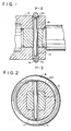
- Fig. 1 is a cross sectional view of a socket positioned upon the shank of a pneumatically powered and tool showing a socket retainer as found in prior art arrangements;
- Fig. 2 is a sectional view as seen from line 2-2 in Fig. 1;
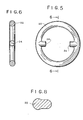
- Fig. 3 is a cross sectional view of a socket positioned upon the shank of a pneumatically powered tool and showing a socket retainer representing an embodiment of the invention;
- Fig. 4 is a sectional view as seen from line 4-4 in Fig. 3;
- Fig. 5 is a plan view of the socket retainer shown in Figs. 3 and 4;
- Fig. 6 is a cross sectional view as seen from line 6-6 in Fig. 5;
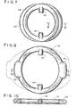
- Fig. 7 is a plan view of a socket retainer illustrating another embodiment of the invention.
- Fig. 8 is a cross sectional view as seen from line 8-8 in Fig. 7;
- Fig. 9 is a plan view of a socket retainer illustrating another embodiment of the invention; and
- Fig. 10 is a sectional view as seen from line 10-10 in Fig. 9.
- Referring now to Figs. 1 and 2,
numeral 10 identifies the work drive shaft of a high speed, pneumatically driven hand-held tool (not shown), and 12 is a socket member positioned thereupon. Ahole 14 is arranged to extend through the drive shaft and socket for receipt of aholding pin 16. A toroidal element in the form of an "0" typeelastic ring 18, is positioned in acircumferential groove 20 formed on the surface of the socket member, whereby thepin 16 is enclosed in thehold 14. Such an arrangement illustrates a socket retainer well known in the prior art. - When the drive shaft is rotated at high speed, such as happens when the tool is running free, an uncentered holding pin can be driven against the
ring 18 and force or cam it aside allowing the pin to be ejected from the hole and become a projectile. Such a happening may result in injury to personnel or serious property damage. - The subject invention, as seen in Figs. 3 and 4, utilizes an "0" type
elastic ring 22 which has a pair of diametrically arranged inwardlyintegral fingers 24, which are of slightly less diameter than thehole 14. Aholding pin 26, of less length than theholding pin 16 of the Figs. 1 and 2 retainer arrangement, is maintained in thehole 14 by reason of thefingers 24. The dotted line representation of thering 22, illustrates the shape thering 22 may have at high speed tool operation, from which it will be apparent that thepin 26 cannot be ejected from thehole 14. - The design of the
ring 22 to be functionally effective, must assure that pretension of the ring, under static conditions, must exceed the centrifugal force generated at maximum R.P.M. of the tool. Ring pretension can be calculated as follows: - Ring pretension > 0.0000283 WRy2
- wherein W = Weight of the heaviest section of the ring (i.e. region of fingers 24)
- R = Effective Radius (distance from center of rotation/center of gravity of section)
- V = Max R.P.M.
- The foregoing formula can be found in "Machinery Handbook", 20th Edition, International Press, 1975.
- While many different elastic materials may be used, Nitrile Buna IV has been used with success.
- The "0"
ring 28, illustrated in Fig. 7, is alike in structure to "0" ring 22, however, theregions 30, midway between thefingers 24, are somewhat greater in cross section area than the remaining diametrical portions of the ring, because of progressively increasing radii as seen in Fig. 7. The increasedcross section area 30 adds weight to counterbalance the weight of thefingers 24, so that centrifugal force will tend to expand the ring into an oval shape at high speed, with the minor diameter of the oval being in the region of the fingers. Such will assure that thefingers 24 will not be forced out ofhole 14. Another form of a mid-weighted ring is illustrated in Figs. 9 and 10, wherein thering 32 has apposedweighted regions 34, which are not tapered, but are relatively short and concentrated. Thering 32 will provide operating characteristics similar to that of thering 30. An expanded position of thering 32 at high speed tool operation is illustrated in dotted lines in Fig. 9. - It is to be noted that the
fingers 24 of the ring will support the ring in position on the socket even if agroove 20 is not used on the socket. Such an arrangement would provide a reduction in fabrication cost of the socket. Furthermore, while the cross-section ofrings - The retension value for
rings - Centrifugal force of the retaining lug portion of ring
- <Centrifugal force of theadded section @90° to the retaining lugs. or

- From the foregoing it will be seen that the embodiments of the invention disclosed above will sati sfy the objectives set forth hereinbefore.
- While the invention has been disclosed in preferred embodiments illustrated and explained herein, it is possible that variations in design may be made without departing from the spirit of the invention, hence, the inventors reserve the right to all variations encompassed by the claims which follow.
Claims (7)
1. An elastic ring (18, 22, 28, 32) for use in maintaining a pin (16, 26) in a hole (14) formed in a socket (12) and a work drive shaft (10) of a rotary tool, characterized by said ring being toroidal in shape and having integral fingers (24) projecting inwardly from the inner surface of the ring, said fingers being arranged to enter the ends of said hole (14).
2. An elastic ring in accordance with claim 1, characterized in that said fingers (24) are diametrically disposed.
3. An elastic ring in accordance with claim 2, characterized in that the diameter of the fingers (24) is substantially the same as the cross sectional diameter of the ring.
4. An elastic ring in accordance with claim 3, characterized in that the regions (30, 34) midway between the fingers are of greater cross section-than other cross section regions of the ring.
5. An elastic ring in accordance with claim 4, characterized in that said midway regions (30) are formed by progressively increasing radii which are at a maximum at the mid point of the midway regions.
6. An elastic ring in accordance with claim 4, characterized in that said midway regions (34) are relatively short and concentrated about midpoint of the midway regions.
7. A socket and drive shaft assembly coupled by a pin (16, 26) in a hole (14) extending through the socket (12) and the drive shaft (10), said pin being maintained in said hole by an elastic ring according to any of the preceding claims.
Applications Claiming Priority (2)
| Application Number | Priority Date | Filing Date | Title |
|---|---|---|---|
| US404556 | 1982-08-02 | ||
| US06/404,556 US4477096A (en) | 1982-08-02 | 1982-08-02 | Socket retainer |
Publications (1)
| Publication Number | Publication Date |
|---|---|
| EP0100577A1 true EP0100577A1 (en) | 1984-02-15 |
Family
ID=23600076
Family Applications (1)
| Application Number | Title | Priority Date | Filing Date |
|---|---|---|---|
| EP83201118A Ceased EP0100577A1 (en) | 1982-08-02 | 1983-07-27 | Socket retainer |
Country Status (3)
| Country | Link |
|---|---|
| US (1) | US4477096A (en) |
| EP (1) | EP0100577A1 (en) |
| JP (1) | JPS5942236A (en) |
Families Citing this family (19)
| Publication number | Priority date | Publication date | Assignee | Title |
|---|---|---|---|---|
| US4627761A (en) * | 1984-09-28 | 1986-12-09 | Snap-On Tools Corporation | Retainer |
| US4732059A (en) * | 1986-12-30 | 1988-03-22 | A.T. & G. Company | Driver for reinforcement bar chemical anchor |
| US4838189A (en) * | 1987-10-06 | 1989-06-13 | Jaakko Kurhi | Mast attachment for quick connect and disconnect |
| JPH0583205U (en) * | 1992-04-17 | 1993-11-12 | 大和ハウス工業株式会社 | Temporary fixing bolt |
| US6016598A (en) * | 1995-02-13 | 2000-01-25 | Akzo Nobel N.V. | Method of manufacturing a multilayer printed wire board |
| US5897121A (en) * | 1998-07-20 | 1999-04-27 | Case; Gregory | Drill attachment and tool for actuating jacks on trailers |
| CN1283418C (en) * | 2001-10-03 | 2006-11-08 | 京都机械工具株式会社 | Socket wrench for power tool |
| US7413366B2 (en) * | 2003-12-09 | 2008-08-19 | Unger Marketing International, Llc | Connecting members and methods for connecting implements to extension poles |
| US7363840B1 (en) * | 2006-12-13 | 2008-04-29 | Farley D Gray | Retaining device with high modulus polymer insert and socket wear indicator |
| DE602007008424D1 (en) * | 2007-09-24 | 2010-09-23 | Bosch Gmbh Robert | Rotating tool with numerous interfaces for tool attachment |
| DE102010002352B4 (en) * | 2010-02-25 | 2021-03-18 | Robert Bosch Gmbh | Hand machine tool |
| USD637895S1 (en) | 2010-04-09 | 2011-05-17 | Unger Marketing International, Llc | Connecting cone |
| US10441120B1 (en) | 2010-04-30 | 2019-10-15 | Unger Marketing International, Llc | Universal connecting members |
| USD634087S1 (en) | 2010-04-30 | 2011-03-08 | Unger Marketing International, Llc | Cleaning tool grip |
| USD896626S1 (en) | 2019-02-28 | 2020-09-22 | Unger Marketing International, Llc | Tool connector |
| US11597062B2 (en) | 2020-10-30 | 2023-03-07 | Gary Raymond KRUPEY | Socket adaptor |
| US11897096B2 (en) | 2021-06-15 | 2024-02-13 | D. Gray Farley | Expanded-stretch retaining device with expanded size range |
| US12311511B2 (en) * | 2021-08-02 | 2025-05-27 | Snap-On Incorporated | Anti-backlash retention socket |
| TWI806602B (en) * | 2022-05-11 | 2023-06-21 | 優鋼機械股份有限公司 | Elastic element and hand tool |
Citations (4)
| Publication number | Priority date | Publication date | Assignee | Title |
|---|---|---|---|---|
| US2881884A (en) * | 1955-01-12 | 1959-04-14 | Chicago Pneumatic Tool Co | Impact clutch |
| US3549160A (en) * | 1968-12-04 | 1970-12-22 | Skil Corp | Socket retention assembly |
| GB1394403A (en) * | 1972-01-31 | 1975-05-14 | Atlas Copco Ab | Impact wrench |
| US4304500A (en) * | 1980-04-18 | 1981-12-08 | Texaco Inc. | Retainer for impact tool couplings |
Family Cites Families (5)
| Publication number | Priority date | Publication date | Assignee | Title |
|---|---|---|---|---|
| US1635929A (en) * | 1925-04-08 | 1927-07-12 | Elmer C Dean | Universal flexible shaft |
| US2326317A (en) * | 1939-11-22 | 1943-08-10 | Chieago Pneumatic Tool Company | Impact wrench |
| US2304038A (en) * | 1940-05-28 | 1942-12-01 | Ingersoll Rand Co | Locking device |
| GB1159912A (en) * | 1967-03-10 | 1969-07-30 | Firth Cleveland Fastenings Ltd | Means for Connecting a Rotatable Member to a Shaft. |
| SU679736A1 (en) * | 1978-01-03 | 1979-08-15 | Предприятие П/Я А-7760 | Retaining device |
-
1982
- 1982-08-02 US US06/404,556 patent/US4477096A/en not_active Expired - Fee Related
-
1983
- 1983-07-27 EP EP83201118A patent/EP0100577A1/en not_active Ceased
- 1983-07-29 JP JP58137937A patent/JPS5942236A/en active Pending
Patent Citations (4)
| Publication number | Priority date | Publication date | Assignee | Title |
|---|---|---|---|---|
| US2881884A (en) * | 1955-01-12 | 1959-04-14 | Chicago Pneumatic Tool Co | Impact clutch |
| US3549160A (en) * | 1968-12-04 | 1970-12-22 | Skil Corp | Socket retention assembly |
| GB1394403A (en) * | 1972-01-31 | 1975-05-14 | Atlas Copco Ab | Impact wrench |
| US4304500A (en) * | 1980-04-18 | 1981-12-08 | Texaco Inc. | Retainer for impact tool couplings |
Also Published As
| Publication number | Publication date |
|---|---|
| JPS5942236A (en) | 1984-03-08 |
| US4477096A (en) | 1984-10-16 |
Similar Documents
| Publication | Publication Date | Title |
|---|---|---|
| EP0100577A1 (en) | Socket retainer | |
| US5125755A (en) | Polymeric tolerance ring | |
| JP3854873B2 (en) | Vibration damper between two components | |
| US5182976A (en) | Spring beamed shock absorbing circular saw blade body | |
| US4134438A (en) | Locking device for threaded fasteners | |
| JP3578687B2 (en) | A device for transmitting torque from an internal combustion engine to a compressor | |
| US5435680A (en) | Screw drive construction | |
| US5000721A (en) | Clutch apparatus | |
| US3485062A (en) | Flexible coupling | |
| EP0205156A1 (en) | A gear assembly adapted for mating with a third gear without backlash | |
| CA2113691A1 (en) | Wand-type hand mixer having a removable operating head | |
| US5048571A (en) | Protective cover for end yoke | |
| KR0148359B1 (en) | Friction pad carrier disc, in particular for an automotive vehicle | |
| US4636171A (en) | Dental polishing tip | |
| US20050178253A1 (en) | Screwdriver tool | |
| US4767381A (en) | Boot restraint for plunging universal joint | |
| EP0666144A1 (en) | Device for blocking a piece on a support plane like a table for operating machines | |
| US6925718B2 (en) | Tool head | |
| US4920289A (en) | Bearing holder with resilient retaining pawls | |
| US6425837B1 (en) | Power transmission | |
| US5450776A (en) | Security fastener removal tool | |
| US4767233A (en) | Impeller mounting apparatus | |
| JPH06297218A (en) | Tools and tool holders for handheld devices | |
| US4290711A (en) | Key system for shaft and gear or the like | |
| US4304500A (en) | Retainer for impact tool couplings |
Legal Events
| Date | Code | Title | Description |
|---|---|---|---|
| PUAI | Public reference made under article 153(3) epc to a published international application that has entered the european phase |
Free format text: ORIGINAL CODE: 0009012 |
|
| AK | Designated contracting states |
Designated state(s): AT BE CH DE FR GB IT LI LU NL SE |
|
| 17P | Request for examination filed |
Effective date: 19840612 |
|
| STAA | Information on the status of an ep patent application or granted ep patent |
Free format text: STATUS: THE APPLICATION HAS BEEN REFUSED |
|
| 18R | Application refused |
Effective date: 19851115 |
|
| RIN1 | Information on inventor provided before grant (corrected) |
Inventor name: GIARDINO, DAVID ANDREW Inventor name: WALLACE, WILLIAM KEITH |