EP0100664B1 - Cuvette à échantillon et arrangement de couvercle pour un analyseur clinique - Google Patents
Cuvette à échantillon et arrangement de couvercle pour un analyseur clinique Download PDFInfo
- Publication number
- EP0100664B1 EP0100664B1 EP83304395A EP83304395A EP0100664B1 EP 0100664 B1 EP0100664 B1 EP 0100664B1 EP 83304395 A EP83304395 A EP 83304395A EP 83304395 A EP83304395 A EP 83304395A EP 0100664 B1 EP0100664 B1 EP 0100664B1
- Authority
- EP
- European Patent Office
- Prior art keywords
- cup
- cap
- assembly
- accordance
- cups
- Prior art date
- Legal status (The legal status is an assumption and is not a legal conclusion. Google has not performed a legal analysis and makes no representation as to the accuracy of the status listed.)
- Expired
Links
Images
Classifications
-
- B—PERFORMING OPERATIONS; TRANSPORTING
- B01—PHYSICAL OR CHEMICAL PROCESSES OR APPARATUS IN GENERAL
- B01L—CHEMICAL OR PHYSICAL LABORATORY APPARATUS FOR GENERAL USE
- B01L3/00—Containers or dishes for laboratory use, e.g. laboratory glassware; Droppers
- B01L3/50—Containers for the purpose of retaining a material to be analysed, e.g. test tubes
- B01L3/508—Rigid containers without fluid transport within
- B01L3/5082—Test tubes per se
-
- G—PHYSICS
- G01—MEASURING; TESTING
- G01N—INVESTIGATING OR ANALYSING MATERIALS BY DETERMINING THEIR CHEMICAL OR PHYSICAL PROPERTIES
- G01N21/00—Investigating or analysing materials by the use of optical means, i.e. using sub-millimetre waves, infrared, visible or ultraviolet light
- G01N21/01—Arrangements or apparatus for facilitating the optical investigation
- G01N21/03—Cuvette constructions
Definitions
- This invention relates to analyzing apparatus in which fluid samples are to be tested, such as, for instance biological samples used in the testing of certain body fluids or disease. More particularly, this invention relates to a receptacle assembly for holding the samples for testing by an analyzer apparatus.
- the receptacle assembly comprises a cap and plural cup structure which is particularly suitable for throwing away after being used once, and in that connection is preferably formed of insert plastic material.
- specimen receptacles Many types of specimen receptacles are known in the art.
- Automatic analyzing apparatus for testing fluid samples are also well known in the art, including the use therewith of throw-away specimen cups formed of plastic, and having individual caps each adapted for snap attachment to the respective cup.
- the individual prior art specimen cups have also been somewhat inadequate because they retain substantial residues of quantities of serum which is lost upon disposal of the cup which becomes substantially costly in mass testing procedures. Also the prior art cups are impractical when limited quantities of serum are only available.
- US-A-2958439 discloses a specimen cup and cap assembly for a clinical analyzer apparatus, comprising a cup and a cap having means thereon for releasably attaching the cup to the cap as an assembly.
- the cap can be snapped into and out of holding coaction with the cup.
- the upper portion of the cup comprises the attaching and can means spaced circumferentially about periphery of the cup at the upper end thereof for interlocking coaction with complementary attaching and can means on the cap.
- US-A-4278437 discloses a specimen cup and cap assembly for a clinical analyzer apparatus, comprising a cup and a cap having means thereon for releasably attaching the cup to the cap as an assembly.
- the cap can be snapped into and out of holding coaction with the cup.
- the cap has a diaphragm which, when pierced by a needle, provides access from the exterior to the interior of the cup.
- the present invention provides a specimen cup and cap assembly for a clinical analyzer apparatus, comprising a strip-like cap having a plurality of generally vertically extending spaced openings therethrough, a plurality of separate specimen cups, and means on said cap and on each said cups for releasably attaching said cups to said cap as an assembly, whereby each of said openings provide access from the exterior to the interior of a respective one said cups, said openings being adapted to provide access for and automatic probe of the clinical analyzer apparatus.
- the strip-like cap preferably includes means adapted for snap-fastening coaction with a plurality of specimen cups.
- the invention further provides a specimen cup adapted for assembly with a cap for use in a clinical analyzer apparatus, said cup comprising an upper portion possessing general flexibility so that said cup can be snapped into and out of holding coaction with an associated cap upon respectively upward and downward force applied to said cup with respect to said cap, said upper portion comprising attaching and cam means spaced circumferentially about the periphery of said cup at the upper end thereof, and being so constructed and arranged that said attaching and cam means can flex generally radially inwardly upon either upward movement of said cup with respect to an associated cap or upon downward movement of the associated cap with respect to said cup, for causing interlocking coaction between said attaching and cam means on said cup and complementary attaching and cam means on the cap.
- the invention also provides a cap adapted for assembly with a plurality of specimen cups for use for instance in a clinical analyzer apparatus, said cap comprising an arcuate strip of material having a plurality of generally vertically extending openings therethrough, and means on the underside of said cap for releasably attaching a plurality of associated cups to the cap as an assembly, said means coacting with each of said openings for orientating a respective cup in communicating relation with the respective of said openings in said cap from exterior of said cap.
- the invention or at least embodiments thereof enables the handling and/or transfer of a plurality of specimen cups at one time to and from a transport ring of the analyzer, or the like, thus materially shortening the time for loading and unloading such transport ring.
- a plurality of specimen cups can thus be expeditiously assembled and disassembled from a strip-type cap, for handling such plurality of specimen cups all at one time.
- an arrangement of interlocking means including cam means, is provided on the individual specimen cups and on the associated cap strip to facilitate the assembly of the cap strip with a plurality of the cups.
- the specimen cups may include an arrangement of interlocking barbs and cam surfaces for facilitating the assembly and disassembly of the cups to and from the strip cap, to provide an expeditious snap-on and snap-off cap arrangement, that is sufficient to handle a considerable axial load, but wherein the cap can be still readily removed from the cups when so desired.
- the cups are preferably so constructed and arranged as to permit expeditious filling thereof by pouring, and each of the cups preferably has a bottom shape that minimizes the amount of residual fluid therein upon aspiration of the individual cup.
- the assembly of the invention is preferably such as can be thrown away after one use thereof, thus obviating the necessity of cleaning and storing thereof for future use.
- the strip-like cap is preferably of arcuate segmental form.
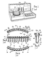
- Such apparatus conventionally includes a transport ring 12 which has a plurality of openings 12a therein disposed in a circular pattern, for receiving for instance, specimen cups 14 (Figs. 3 and 5) which are supported in such openings and contain the specimens to be analyzed by the apparatus.
- the inner ring 16 of vessels are the specimen cups illustrated in connection with the invention.
- a rotatable and powered head 18 on the apparatus may include an arm 18a which is movably transversely with respect to a transport ring 12 and which may include a vertically movable probe 20 for taking material from the respective serum cup.
- Apparatus 10 may be of the general type identified as an Impact 400 Analyzer, produced by the present applicant. Reference may also be had to U.S.
- FIGS 2-5 show a cap and cup assembly 22 according to the invention for use in the analyzer of Figure 1, but it will be understood that this may be used in other types of analyzers and other apparatus wherein it is an advantage to be able to handle a plurality of the specimen cup members at one time, instead of individually.
- Assembly 22 comprises a strip-like cap 24, having a plurality of the aforementioned specimen cups 14 removably secured thereto, as shown for instance in Figures 2-5.
- Cap 24 has a plurality of openings 26 extending therethrough and disposed in generally spaced relation lengthwise of the cap. The openings may have indicia 28, in this instance numbers, associated therewith, for identifying the particular specimen cup openings.
- Each of the openings 26 is preferably defined by a funnel-like structure 26a extending downwardly from the top surface of the cap, for a purpose described below.
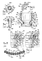
- FIG. 12 which shows the bottom of the strip cap 24, there is associated with each of the openings 26 in the cap, means 30 for interlocking the cups 14 in the strip cap in releasable relationship.
- means 30 for interlocking the cups 14 in the strip cap in releasable relationship.
- Such means 30 provides a snap-fastening arrangement between the cap 24 and the cups 14.
- Means 30, in the embodiment illustrated, comprises an inwardly extending shoulder 30a circumscribing the respective recess 31 in the cap receiving the upper end of the respective cup therein, and adapted for interlocking coaction with complementary fastening means 32 ( Figures 9 and 10) on the cups 14, as is described below in greater detail.
- the strip cap 24 is preferably formed of plastic so that it may be thrown away after one use thereof, and. a suitable plastic material has been found to be medium impact ABS plastic. Such plastic material is preferably white for marker readability.
- the height H ( Figure 10) of the strip cap is such as to provide adequate space for writing on the exterior side surfaces of the cap by the analyzer operator, and the plastic material is preferably of such a type that such writing can be accomplished by conventional writing instruments. Sufficient space is provided on the top surface to provide suitable indicia for identifying each individual cup, as aforesaid.
- the cups 14 preferably comprise a widened mouth portion 34 ( Figure 7) which facilitates the pouring of a specimen into the cup, an elongate stem of body portion 36 depending from the mouth portion 34, and a tip portion 38 which preferably has a highly polished spherical-like interior surface 38a for facilitating the removal of the specimen material in the cup as by aspiration from the cup, and thus minimizes the amount of residual fluid when the cup is aspirated, as for instance by the automatic probe 20.
- the mouth portion 34 is preferably connected to the stem or body portion 36 by inwardly sloping surface 40 disposed at an angle of approximately 45° with respect to the horizontal, with the tip portion 38 being connected to the stem or body portion 36, on its interior surface, by downwardly and inwardly sloping side wall surfaces 42, as best illustrated in Figure 7.
- the cup 14 may have a plurality of circumferentially spaced protrusions 44 thereon, adapted to support the cup in an opening in a support surface, such as the aforementioned transport ring 12, and to prevent said cup from falling through any hole in the transport ring 12.
- Each cup is provided at its upper end with the aforementioned interlocking means 32, which in the embodiment illustrated comprise spaced barbs 46, connected with thin web sections 46a.
- Each of the barbs 46 has a cam surface 48 thereon adapted to camming engagement with a complementary cam surface 50 ( Figures 9 and 10) on the shoulder 30a of cap member 24, so as to cause inward flexing or general radial movement of the barbs during assembly of the cap onto the cup or vice versa.
- Aforementioned cam surfaces 48 and 50 preferably slope at an angle of approximately 15° with respect to the vertical.
- the webs 46a flex or crease so as to permit the barbs 46 on the cup to pass the shoulder 30a on the cap until the barbs clear the shoulder, at which time they snap back into their non-deformed positions and into snap-fastening coaction with the shoulder 30a on the cap, to interlock the cap and the cups together.
- the top of the cap generally has a clearance C ( Figure 9) at top to resist disengagement when bumped sideways and to provide overtravel to ensure complete installation of all cups.
- the aforementioned funnel portion 26a aids in preventing evaporation of the specimen contained in the respective cup, thus aiding in preserving the accuracy of the tests run thereon.
- Each barb 46 on the cup preferably has a sloping undersurface 54 ( Figure 8) which is adapted for camming engagement with the sloping surface 56 on the respective shoulder 30 of the cap, so as to provide a directional engagement force, the barbs being thus easily installed and more difficult to remove.
- the barbs again swing or move inwardly against the resistance to creasing or crimping of the webs 46a until the head of the barbs on the cup move past the respective shoulder 30 on the cap, at which time the barbs swing back to their normal non-deformed position, as illustrated for instance in Figures 7, 8 and 9.
- Aforementioned surfaces 54 and 56 preferably slope at an angle of approximately 30° with respect to the horizontal.
- the cups are preferably formed of plastic so that they can be readily thrown away after one use thereof.
- a suitable material has been found to be polyethylene plastic, and a mixture of approximately 25% by weight of high density polyethylene and approximately 75% by weight of low density polyethylene has been found to be particularly suitable for providing the cups of the invention with the desired flexibility.
- plastic materials may also be used.
- the interlocking coaction between the shoulder means 30 on the cap with the interlocking means 32 on the cups provides a sufficient connection to support the axial load of the specimen material disposed in the cups, and is such as preferably to provide for a minimum holding power of approximately 185 g (6.5 ounce) axial load on the respective cup.
- Such as arrangement provides for the maintenance of the assembly of the cap and the cups for the purpose to which they are adapted for use, and yet provides for ready separation of the cups from the cap or vice versa, when that is deemed desirable or necessary.
- the rounded exterior configuration of the end tip of the cups facilitates the entry of the cap-cup assembly into the receiving openings in support plate, such as for instance the aforementioned transport plate 12 of the analyzer apparatus.
Landscapes
- Health & Medical Sciences (AREA)
- Chemical & Material Sciences (AREA)
- Analytical Chemistry (AREA)
- General Health & Medical Sciences (AREA)
- Immunology (AREA)
- Biochemistry (AREA)
- Life Sciences & Earth Sciences (AREA)
- General Physics & Mathematics (AREA)
- Physics & Mathematics (AREA)
- Pathology (AREA)
- Hematology (AREA)
- Clinical Laboratory Science (AREA)
- Chemical Kinetics & Catalysis (AREA)
- Automatic Analysis And Handling Materials Therefor (AREA)
- Investigating Or Analysing Biological Materials (AREA)
- Devices For Use In Laboratory Experiments (AREA)
Claims (26)
Applications Claiming Priority (2)
| Application Number | Priority Date | Filing Date | Title |
|---|---|---|---|
| US06/404,477 US4799599A (en) | 1982-07-30 | 1982-07-30 | Specimen cup and cap assembly for clinical analyzer |
| US404477 | 1995-03-14 |
Publications (3)
| Publication Number | Publication Date |
|---|---|
| EP0100664A2 EP0100664A2 (fr) | 1984-02-15 |
| EP0100664A3 EP0100664A3 (en) | 1984-10-10 |
| EP0100664B1 true EP0100664B1 (fr) | 1987-03-11 |
Family
ID=23599759
Family Applications (1)
| Application Number | Title | Priority Date | Filing Date |
|---|---|---|---|
| EP83304395A Expired EP0100664B1 (fr) | 1982-07-30 | 1983-07-29 | Cuvette à échantillon et arrangement de couvercle pour un analyseur clinique |
Country Status (4)
| Country | Link |
|---|---|
| US (1) | US4799599A (fr) |
| EP (1) | EP0100664B1 (fr) |
| JP (1) | JPS5935141A (fr) |
| DE (1) | DE3370142D1 (fr) |
Families Citing this family (42)
| Publication number | Priority date | Publication date | Assignee | Title |
|---|---|---|---|---|
| CH663476A5 (fr) * | 1985-07-08 | 1987-12-15 | Serono Diagnostics Ltd | Enceinte pour le dosage d'anticorps ou d'antigenes dans un liquide biologique. |
| US5019243A (en) * | 1987-04-03 | 1991-05-28 | Mcewen James A | Apparatus for collecting blood |
| US4855110A (en) * | 1987-05-06 | 1989-08-08 | Abbott Laboratories | Sample ring for clinical analyzer network |
| DE3738375A1 (de) * | 1987-11-12 | 1989-05-24 | Amelung Gmbh Heinrich | Vorrichtung zum einsetzen von mit stahlkugeln bestueckten testkuevetten in eine messvorrichtung eines analysegeraetes |
| US4960219A (en) * | 1989-09-08 | 1990-10-02 | Abbott Laboratories | Snap cap |
| DE9016832U1 (de) * | 1990-12-17 | 1991-03-07 | Labor Laborgeräte + Analysensysteme Vertriebsgesellschaft mbH, 2070 Ahrensburg | Küvette zur Aufnahme von auf optischem Wege zu untersuchenden Substanzen |
| SG43896A1 (en) * | 1991-05-07 | 1997-11-14 | Hoffmann La Roche | Cuvette for performing optical measurements |
| CA2067695C (fr) * | 1991-06-06 | 1997-07-08 | James A. Burns | Assemblage de tube de microcollecte de sang |
| USD345611S (en) | 1991-07-22 | 1994-03-29 | Pb Diagnostic Systems, Inc. | Sample cup |
| US5575978A (en) * | 1992-03-27 | 1996-11-19 | Abbott Laboratories | Sample container segment assembly |
| US6190617B1 (en) * | 1992-03-27 | 2001-02-20 | Abbott Laboratories | Sample container segment assembly |
| JP3439210B2 (ja) * | 1992-03-27 | 2003-08-25 | アボツト・ラボラトリーズ | 自動連続ランダム・アクセス分析システム及びその構成要素 |
| US5354483A (en) * | 1992-10-01 | 1994-10-11 | Andronic Technologies, Inc. | Double-ended tube for separating phases of blood |
| FI925117A0 (fi) * | 1992-11-11 | 1992-11-11 | Labsystems Oy | Kyvettmatris |
| US5384096A (en) * | 1993-05-12 | 1995-01-24 | Becton, Dickinson And Company | Microcollection tube assembly |
| USD356643S (en) | 1993-05-27 | 1995-03-21 | Becton Dickinson And Company | Microcollection tube |
| DE4412286A1 (de) * | 1994-04-09 | 1995-10-12 | Boehringer Mannheim Gmbh | System zur kontaminationsfreien Bearbeitung von Reaktionsabläufen |
| DE4428434A1 (de) * | 1994-08-11 | 1996-02-15 | Boehringer Ingelheim Kg | Verschlußkappe und Verfahren zur gasblasenfreien Füllung von Behältern |
| DE19615422A1 (de) * | 1996-04-19 | 1997-11-20 | Boehringer Ingelheim Kg | Zweikammer-Kartusche für treibgasfreie Dosieraerosole |
| US5856194A (en) | 1996-09-19 | 1999-01-05 | Abbott Laboratories | Method for determination of item of interest in a sample |
| US5795784A (en) | 1996-09-19 | 1998-08-18 | Abbott Laboratories | Method of performing a process for determining an item of interest in a sample |
| USD401697S (en) | 1997-05-21 | 1998-11-24 | Abbott Laboratories | Container |
| US5915583A (en) * | 1997-05-21 | 1999-06-29 | Abbott Laboraties | Container |
| CA2247589C (fr) * | 1997-10-02 | 2007-01-09 | F. Hoffmann-La Roche Ag | Dispositif pour le manutention automatique de contenants fermes par couvercle filete |
| USD439673S1 (en) | 1998-10-06 | 2001-03-27 | Sorenson Bioscience | Multi-well microcentrifuge tube |
| US6669911B1 (en) * | 2001-01-31 | 2003-12-30 | David W. Swanson | Frame for multiwell tray |
| EP1232792B1 (fr) * | 2001-02-20 | 2006-09-06 | F. Hoffmann-La Roche Ag | Matrice linéaire de cuvettes, matrice bidimensionnelle de cuvettes construite avec une telle matrice linéaire et système comprenant de telles matrices bidimensionnelles de cuvettes |
| US6835316B2 (en) | 2001-04-09 | 2004-12-28 | Medtronic, Inc. | Clam shell blood reservoir holder with index line |
| US6589153B2 (en) | 2001-09-24 | 2003-07-08 | Medtronic, Inc. | Blood centrifuge with exterior mounted, self-balancing collection chambers |
| US6869854B2 (en) | 2002-07-18 | 2005-03-22 | International Business Machines Corporation | Diffused extrinsic base and method for fabrication |
| DE102006001882A1 (de) * | 2006-01-13 | 2007-07-19 | Roche Diagnostics Gmbh | Zu einem Verbund zusammengefasste Gruppe von Reagenzienträgern |
| US7798837B1 (en) | 2009-04-03 | 2010-09-21 | Ohaus Corporation | Connector security cover |
| US10197480B2 (en) | 2012-11-07 | 2019-02-05 | Sandstone Diagnostics, Inc. | Methods and devices for processing samples and counting cells |
| CA2885845C (fr) | 2012-11-07 | 2019-10-29 | Sandstone Diagnostics, Inc. | Procedes et dispositifs de traitement d'echantillons et de numeration de cellules |
| WO2014124179A1 (fr) | 2013-02-07 | 2014-08-14 | Sandstone Diagnostics, Inc. | Traitement d'échantillons, répartition de fluides et dosage à sédimentation automatisés |
| AU2013202805B2 (en) | 2013-03-14 | 2015-07-16 | Gen-Probe Incorporated | System and method for extending the capabilities of a diagnostic analyzer |
| USD727327S1 (en) * | 2013-11-22 | 2015-04-21 | Compliance Software, Inc. | Compact stand with mobile scanner |
| USD810084S1 (en) | 2016-03-23 | 2018-02-13 | Formfox, Inc. | Mobile scanner |
| US10870109B2 (en) | 2017-05-20 | 2020-12-22 | Sandstone Diagnostics, Inc. | Sample cup |
| US20190127688A1 (en) | 2017-10-26 | 2019-05-02 | The Regents Of The University Of California | Drosophila Stock Maintenance |
| USD867611S1 (en) | 2018-01-29 | 2019-11-19 | Sandstone Diagnostics, Inc. | Sample cup |
| US20230226541A1 (en) * | 2022-01-18 | 2023-07-20 | Hollister Incorporated | Fluid absorption test tube |
Family Cites Families (17)
| Publication number | Priority date | Publication date | Assignee | Title |
|---|---|---|---|---|
| US2949204A (en) * | 1954-12-31 | 1960-08-16 | Illinois Tool Works | Closure device |
| US2990076A (en) * | 1958-04-11 | 1961-06-27 | Morton B Stull | Closure cap and container neck construction |
| US3247994A (en) * | 1958-09-16 | 1966-04-26 | F G M & Co | Plastic caps for use as closure for containers |
| US2958439A (en) * | 1959-04-29 | 1960-11-01 | Donald E Yochem | Container and closure |
| US3120318A (en) * | 1962-05-21 | 1964-02-04 | Herbert W Rigor | Locking container closure |
| US3362556A (en) * | 1964-12-14 | 1968-01-09 | John E. Waldrum | Closures |
| US3441383A (en) * | 1966-10-26 | 1969-04-29 | Francis C Moore | Multiple cup tray |
| GB1247520A (en) * | 1967-10-23 | 1971-09-22 | Ole Rues | Container for laboratory use |
| FR2086518A5 (fr) * | 1969-11-19 | 1971-12-31 | Captocap Ltd | |
| US3627431A (en) * | 1969-12-22 | 1971-12-14 | John Victor Komarniski | Densitometer |
| US3715063A (en) * | 1970-03-18 | 1973-02-06 | Lion Fat Oil Co Ltd | Cap structure holding an inner closure |
| US3680967A (en) * | 1970-09-14 | 1972-08-01 | Technicon Instr | Self-locating sample receptacle having integral identification label |
| US3838550A (en) * | 1972-08-22 | 1974-10-01 | Owens Illinois Inc | Method and apparatus for packaging |
| US3907146A (en) * | 1973-11-15 | 1975-09-23 | Mack Robert Fields | Primary closure |
| US3983999A (en) * | 1975-05-23 | 1976-10-05 | Jay Morton | Multi-container package |
| US4278437A (en) * | 1979-04-09 | 1981-07-14 | Jan Haggar | Fluid specimen holder for biological fluid testing |
| US4289252A (en) * | 1980-07-21 | 1981-09-15 | Container Corporation Of America | Hermetically sealed container |
-
1982
- 1982-07-30 US US06/404,477 patent/US4799599A/en not_active Expired - Fee Related
-
1983
- 1983-07-22 JP JP58133016A patent/JPS5935141A/ja active Pending
- 1983-07-29 DE DE8383304395T patent/DE3370142D1/de not_active Expired
- 1983-07-29 EP EP83304395A patent/EP0100664B1/fr not_active Expired
Also Published As
| Publication number | Publication date |
|---|---|
| EP0100664A3 (en) | 1984-10-10 |
| DE3370142D1 (en) | 1987-04-16 |
| US4799599A (en) | 1989-01-24 |
| JPS5935141A (ja) | 1984-02-25 |
| EP0100664A2 (fr) | 1984-02-15 |
Similar Documents
| Publication | Publication Date | Title |
|---|---|---|
| EP0100664B1 (fr) | Cuvette à échantillon et arrangement de couvercle pour un analyseur clinique | |
| US4980293A (en) | Dispensing reagents in a specimen well | |
| US5897090A (en) | Puck for a sample tube | |
| AU2002319595B2 (en) | Sample carrier and drip shield for use therewith | |
| EP1155742B1 (fr) | Procédé et dispositif de distribution de liquide | |
| US5005721A (en) | Vial seal | |
| EP2223745B1 (fr) | Méthode de chargement des réactifs dans un dispositif de manutention des échantillons d'un dispositif pour les analyses automatisés | |
| EP0583078B1 (fr) | Appareil et méthode de manipulation d'échantillons | |
| EP2356209B1 (fr) | Système de plateau pour d'échantillons | |
| US5591642A (en) | Fluid dispensing method | |
| US5589137A (en) | Specimen carrier | |
| US4699884A (en) | Process and apparatus for the simultaneous application of a multiplicity of liquid samples to an object stage | |
| EP0293075A2 (fr) | Pipette | |
| US20030129089A1 (en) | Pipette tip reloading system | |
| AU2016247157A1 (en) | Systems, methods, and apparatuses for performing automated reagent-based assays | |
| JPH0812135B2 (ja) | 試料を多数のアリコットに分画する装置 | |
| US3991896A (en) | Stopper assembly | |
| AU2003220233B2 (en) | Disk testing apparatus | |
| US11426737B2 (en) | Waste disposal system | |
| JP2016224048A (ja) | 廃棄物処分システム | |
| US9157923B2 (en) | Reagent bead inserter | |
| JPH09292392A (ja) | 検査用採便容器及び糞便懸濁液調製方法 | |
| EP1630555A2 (fr) | Dispositif d'analyse à haut débit de cellules | |
| EP0239218A2 (fr) | Appareil pour la détection de micro-organismes | |
| EP1181980A1 (fr) | Stockage de liquide |
Legal Events
| Date | Code | Title | Description |
|---|---|---|---|
| PUAI | Public reference made under article 153(3) epc to a published international application that has entered the european phase |
Free format text: ORIGINAL CODE: 0009012 |
|
| AK | Designated contracting states |
Designated state(s): DE FR GB |
|
| PUAL | Search report despatched |
Free format text: ORIGINAL CODE: 0009013 |
|
| RHK1 | Main classification (correction) |
Ipc: B01L 3/14 |
|
| AK | Designated contracting states |
Designated state(s): DE FR GB |
|
| 17P | Request for examination filed |
Effective date: 19850226 |
|
| GRAA | (expected) grant |
Free format text: ORIGINAL CODE: 0009210 |
|
| AK | Designated contracting states |
Kind code of ref document: B1 Designated state(s): DE FR GB |
|
| REF | Corresponds to: |
Ref document number: 3370142 Country of ref document: DE Date of ref document: 19870416 |
|
| ET | Fr: translation filed | ||
| PLBE | No opposition filed within time limit |
Free format text: ORIGINAL CODE: 0009261 |
|
| STAA | Information on the status of an ep patent application or granted ep patent |
Free format text: STATUS: NO OPPOSITION FILED WITHIN TIME LIMIT |
|
| 26N | No opposition filed | ||
| PGFP | Annual fee paid to national office [announced via postgrant information from national office to epo] |
Ref country code: GB Payment date: 19890630 Year of fee payment: 7 |
|
| PGFP | Annual fee paid to national office [announced via postgrant information from national office to epo] |
Ref country code: FR Payment date: 19890719 Year of fee payment: 7 |
|
| PGFP | Annual fee paid to national office [announced via postgrant information from national office to epo] |
Ref country code: DE Payment date: 19890727 Year of fee payment: 7 |
|
| PG25 | Lapsed in a contracting state [announced via postgrant information from national office to epo] |
Ref country code: GB Effective date: 19900729 |
|
| GBPC | Gb: european patent ceased through non-payment of renewal fee | ||
| PG25 | Lapsed in a contracting state [announced via postgrant information from national office to epo] |
Ref country code: FR Effective date: 19910329 |
|
| PG25 | Lapsed in a contracting state [announced via postgrant information from national office to epo] |
Ref country code: DE Effective date: 19910403 |
|
| REG | Reference to a national code |
Ref country code: FR Ref legal event code: ST |