EP0100696A1 - Obturateur pour flute permettant d'améliorer l'émission de notes prédéterminées de l'instrument - Google Patents
Obturateur pour flute permettant d'améliorer l'émission de notes prédéterminées de l'instrument Download PDFInfo
- Publication number
- EP0100696A1 EP0100696A1 EP83401279A EP83401279A EP0100696A1 EP 0100696 A1 EP0100696 A1 EP 0100696A1 EP 83401279 A EP83401279 A EP 83401279A EP 83401279 A EP83401279 A EP 83401279A EP 0100696 A1 EP0100696 A1 EP 0100696A1
- Authority
- EP
- European Patent Office
- Prior art keywords
- shutter according
- flute
- shutter
- shape
- flared shape
- Prior art date
- Legal status (The legal status is an assumption and is not a legal conclusion. Google has not performed a legal analysis and makes no representation as to the accuracy of the status listed.)
- Granted
Links
- 239000007799 cork Substances 0.000 description 2
- 230000004048 modification Effects 0.000 description 2
- 238000012986 modification Methods 0.000 description 2
- 239000002184 metal Substances 0.000 description 1
- 239000002991 molded plastic Substances 0.000 description 1
Images


Classifications
-
- G—PHYSICS
- G10—MUSICAL INSTRUMENTS; ACOUSTICS
- G10D—STRINGED MUSICAL INSTRUMENTS; WIND MUSICAL INSTRUMENTS; ACCORDIONS OR CONCERTINAS; PERCUSSION MUSICAL INSTRUMENTS; AEOLIAN HARPS; SINGING-FLAME MUSICAL INSTRUMENTS; MUSICAL INSTRUMENTS NOT OTHERWISE PROVIDED FOR
- G10D9/00—Details of, or accessories for, wind musical instruments
-
- G—PHYSICS
- G10—MUSICAL INSTRUMENTS; ACOUSTICS
- G10D—STRINGED MUSICAL INSTRUMENTS; WIND MUSICAL INSTRUMENTS; ACCORDIONS OR CONCERTINAS; PERCUSSION MUSICAL INSTRUMENTS; AEOLIAN HARPS; SINGING-FLAME MUSICAL INSTRUMENTS; MUSICAL INSTRUMENTS NOT OTHERWISE PROVIDED FOR
- G10D7/00—General design of wind musical instruments
- G10D7/02—General design of wind musical instruments of the type wherein an air current is directed against a ramp edge
- G10D7/026—General design of wind musical instruments of the type wherein an air current is directed against a ramp edge with air currents blown into an opening arranged on the cylindrical surface of the tube, e.g. transverse flutes, piccolos or fifes
-
- G—PHYSICS
- G10—MUSICAL INSTRUMENTS; ACOUSTICS
- G10D—STRINGED MUSICAL INSTRUMENTS; WIND MUSICAL INSTRUMENTS; ACCORDIONS OR CONCERTINAS; PERCUSSION MUSICAL INSTRUMENTS; AEOLIAN HARPS; SINGING-FLAME MUSICAL INSTRUMENTS; MUSICAL INSTRUMENTS NOT OTHERWISE PROVIDED FOR
- G10D9/00—Details of, or accessories for, wind musical instruments
- G10D9/02—Mouthpieces; Reeds; Ligatures
-
- G—PHYSICS
- G10—MUSICAL INSTRUMENTS; ACOUSTICS
- G10D—STRINGED MUSICAL INSTRUMENTS; WIND MUSICAL INSTRUMENTS; ACCORDIONS OR CONCERTINAS; PERCUSSION MUSICAL INSTRUMENTS; AEOLIAN HARPS; SINGING-FLAME MUSICAL INSTRUMENTS; MUSICAL INSTRUMENTS NOT OTHERWISE PROVIDED FOR
- G10D9/00—Details of, or accessories for, wind musical instruments
- G10D9/10—Resonating bodies, e.g. tubes
Definitions
- the invention relates to a shutter for facilitating the emission of predetermined notes from a transverse flute or the like.
- a shutter for facilitating the emission of predetermined notes from a transverse flute or the like.
- the object of the invention is to propose a shutter which facilitates the emission of said notes. This object is achieved by the fact that, according to the invention, there is at least one auxiliary resonator in the obturator opening out onto the air column and produced in the form of a chamber whose length is specifically granted to facilitate '' issuance of at least one predetermined note from the instrument.
- the length of the chamber is granted so that its natural frequency is a binary logarithm of the frequency of the fundamental of the predetermined note.
- the specific resonator is tuned to a sensitive harmonic (one of the upper octaves) of the fundamental of the note in question.
- the room is advantageously designed in the form of a room of variable length which is adjusted for tuning.
- This adjustment can be fixed by one means or another depending on the adjustment means if one wishes an immutable agreement; it can be left free if you want to be able to change it later, if only to adapt it to the different tuning forks in use.
- the specific resonator (s) consist of one or more concentric chambers, advantageously of adjustable length.
- the shutter is honeycombed with holes constituting the specific resonators.
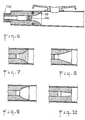
- the shutter comprises an internal piston sliding in an adjustable manner in an annular piston, the front end of which has a choice of a planar shape, a convex flared shape, a concave flared shape, a stepped flared shape , a diverging frustoconical form, or a converging frustoconical form.
- Figure 1 shows a flute 12 with its mouth 13 and, to the left of the mouth hole, a cavity traditionally closed by a cork stopper 14 clamped between two metal plates 15 mounted on a threaded rod 16 whose end 17 is screws into a knurled button 18.
- the cork stopper 14 To be waterproof, the cork stopper 14 must be forced into this conical part of the mouth.
- the coefficient of friction of the plug 14 being greater than the torque delivered by the knurled button 18, the system does not work in the direction of elongation of the cavity (action of screwing the button). The system does not work in the other direction either (unscrewing action), because in this case the button is released without modifying in any way the volume of the cavity question.
- the invention proposes to replace this fixed plug with a system of one or more specific resonators.
- the conventional plug is replaced by a plug made up of one or more concentric pistons sliding in one another and thus forming concentric chambers of adjustable length.
- FIG. 2 only two concentric pistons 19 and 20 are shown.
- a surface 25 with two or more sides makes it possible to rotate the assembly in order to adjust the position thereof while a vernier of the "Palmer" type produced on this surface allows pinpoint its position.
- the central piston 20 slides in the annular piston 19 (a seal 26 being provided).
- a micrometric thread 27 cooperates with the rod of the annular piston 19 to adjust the relative position of the two pistons: a button 28 provided with a "Palmer” type vernier allows fine adjustment.
- the shutter of the invention comprises a main shutter 29 mounted with a seal 30 in the end of the flute body in a fixed position or, preferably adjustable by means of a device not shown.
- the main shutter 29 is honeycombed with holes 31, cylindrical (fig. 7), hexagonal (fig. 8) or others, only one of which has been shown in FIG. 6.
- the bottom of each hole consists of a piston 32 adjustable allowing to tune the length 1 of the hole on a specific frequency improving the emission of a predetermined note.
- each of these holes 31 is carefully tuned to a sensitive harmonic of the fundamental frequencies of the flute.
- each note thus has "its own” resonator 31.
- this system makes it possible, by slightly varying the length of the resonators 31, to individually tune the timbre and the octave ratios of each note of the flute within certain limits.
- the length of the resonators 31 can be fixed, in this case the instrument is constructed in a single tuning fork. One can even then make the plug 29 in molded plastic, the holes 31 being molded to a precalculated length.
- This embodiment gives, compared to the previous one, greater fixity of the notes, which will make it particularly appreciated by novice students. Confirmed artists may prefer the first mode of realization which allows greater personalization of the instrument.
- Figure 6 illustrates a variant of Figure 2, in which an inner piston 120 can slide inside an annular piston 119, which itself can be mounted sliding or not (as shown in Figure 6).
- the originality of this variant resides in the convex flared shape given to the front end of the annular piston 119, analogous to a trumpet horn. Thanks to the movable piston 120 adjustable by the knurled knob 128 the length of the chamber on a harmonic of the fundamental note of the flute; experience shows that the emission of both this fundamental note and other notes, is facilitated. Everything happens as if, for a given note other than the fundamental note, the air column found itself the right length of chord by taking "support" on the area of the flared part corresponding to the right length of bedroom.
- FIGS. 7 to 10 show different shapes which can be given to the front part of the piston 119: a convex flared shape stepped in FIG. 7, a concave flared shape in FIG. 9, a divergent frustoconical shape in FIG. 8, a converging frustoconical shape in FIG. 10.
- a convex flared shape stepped in FIG. 7 a concave flared shape in FIG. 9, a divergent frustoconical shape in FIG. 8, a converging frustoconical shape in FIG. 10.
Landscapes
- Physics & Mathematics (AREA)
- Engineering & Computer Science (AREA)
- Acoustics & Sound (AREA)
- Multimedia (AREA)
- Auxiliary Devices For Music (AREA)
- Portable Nailing Machines And Staplers (AREA)
- Slot Machines And Peripheral Devices (AREA)
- Stringed Musical Instruments (AREA)
- Fluid-Damping Devices (AREA)
- Closing And Opening Devices For Wings, And Checks For Wings (AREA)
- Diaphragms For Electromechanical Transducers (AREA)
- Percussive Tools And Related Accessories (AREA)
- Wing Frames And Configurations (AREA)
- Glass Compositions (AREA)
Abstract
Description
- L'invention concerne un obturateur permettant de faciliter l'émission de notes prédéterminées d'une flûte traversière ou instrument analogue. On sait que dans la plupart des instruments à vent, il existe certaines notes difficiles, parce que leur émission est incertaine tant du point de vue de l'attaque que de la stabilité. C'est par exemple le cas de certaines notes basses de la flûte traversière.
- Le but de l'invention est de proposer un obturateur qui facilite l'émission desdites notes. Ce but est atteint du fait que, selon l'invention, on dispose dans l'obturateur au moins un résonateur auxiliaire débouchant sur la colonne d'air et réalisé sous forme d'une chambre dont on accorde la longueur de façon spécifique pour faciliter l'émission d'au moins une note prédéterminée de l'instrument.
- Avantageusement, on accorde la longueur de la chambre de manière que sa fréquence propre soit un logarithme binaire de la fréquence du fondamental de la note prédéterminée. Autrement dit, le résonnateur spécifique est accordé sur un harmonique sensible (une des octaves supérieures) du fondamental de la note en question.
- Pour ce faire, la chambre est avantageusement conçue sous forme d'une chambre de longueur variable qu'on règle pour l'accord. Ce réglage peut être figé par un moyen ou un autre dépendant du moyen de réglage si l'on désire un accord immuable ; il peut être laissé libre si l'on veut pouvoir le changer ultérieurement, ne serait-ce que pour l'adapter aux différents diapasons en usage.
- Dans un premier exemple préféré de réalisation, le ou les résonateurs spécifiques sont constitués par une ou plusieurs chambes concentriques, avantageusement de longueur réglable.
- Dans un second exemple préféré de réalisation, l'obturateur est alvéolé de trous constituant les résonateurs spécifiques.
- Dans une autre présentation de l'instrument, l'obturateur comporte un piston intérieur coulissant de manière réglable dans un piston annulaire dont l'extrémité frontale présente au choix une forme plane, une forme évasée convexe, une forme évasée concave, une forme évasée étagée, une forme tronconique divergente, ou une forme tronconique convergente.
- L'invention sera mieux comprise grâce à la description qui va suivre, faite en référence aux dessins annexés sur lesquels
- - la figure 1 représente en coupe longitudinale une flûte traversière avec un bouchon classique,
- - la figure 2 représente un premier exemple de réalisation d'un obturateur de flûte conforme à l'invention,
- - la figure 3 représente un deuxième exemple de réalisation d'un obturateur de flûte conforme à l'invention, .
- - les figures 4 et 5 représentent de face deux variantes du deuxième exemple de réalisation de l'obturateur de la figure 3,
- - la figure 6 montre une modification de l'exemple de réalisation de la figure 2, portant sur la forme du piston annulaire,
- - les figures 7 à 10 montrent des variantes de forme du piston annulaire de la figure 6.
- La figure 1 montre une flûte 12 avec son embouchure 13 et, à gauche du trou d'embouchure, une cavité obturée traditionnellement par un bouchon de liège 14 serré entre deux plaques de métal 15 montées sur une tige filetée 16 dont l'extrémité 17 se visse dans un bouton moleté 18.
- Pour être étanche, le bouchon de liège 14 doit être enfoncé à force dans cette partie conique de l'embouchure.
- Le coefficient de frottement du bouchon 14 étant supérieur au couple que délivre le bouton moleté 18, le système ne fonctionne pas dans le sens de l'allongement de la cavité (action de visser le bouton ). Le système ne fonctionne pas dans l'autre sens non plus (action de dévisser), car dans ce cas le bouton se libère sans modifier en quoi que ce soit le volume de la cavité en question.
- L'invention propose de remplacer ce bouchon fixe par un système de un ou plusieurs résonateurs spécifiques.
- Selon un premier mode de réalisation, montré en figure 2, le bouchon classique est remplacé par un bouchon constitué d'un ou plusieurs pistons concentriques coulissant les uns dans les autres et formant ainsi des chambres concentriques de longueur réglable. Sur la figure 2, il n'est représenté que deux pistons concentriques 19 et 20. Le piston annulaire 19, muni d'un étanchéité 21 par joints toriques ou à quatre lobes, peut coulisser dans l'extrémité 22 du corps de flûte, sa position étant réglable grâce à un filetage micrométique 23 coopérant avec une collerette terminale 24. Une surface 25 à deux ou plusieurs pans permet de tourner l'assemblage pour en régler la position tandis qu'un vernier du type "Palmer" réalisé sur cette surface permet d'en repérer avec précision la position.
- Le piston central 20 coulisse dans le piston annulaire 19 (une étanchéité 26 étant prévue). Un filetage micrométrique 27 coopère avec la tige du piston annulaire 19 pour régler la position relative des deux pistons : un bouton 28 muni d'un vernier type "Palmer" permet un réglage fin.
- L'émission des notes graves traditionnellement difficiles sur la flûte est grandement améliorée tout en laissant à l'artiste un "champ de liberté" dans le domaine des fréquences lui permettant un grande souplesse d'interprétation.
- Bien que présentant moins de richesse au niveau des résonateurs spécifiques mais toujours une très grande variété de timbres, on peut concevoir un piston annulaire fixe, et seulement le piston central mobile.
- Au contraire, on peut aussi prévoir plus de deux pistons concentiques.
- Selon un autre mode de réalisation représenté fig. 3 à 5, l'obturateur de l'invention comporte un obturateur principal 29 monté avec une étanchéité 30 dans l'extrémité du corps de flûte en position fixe ou, de préférence réglable au moyen d'un dispositif non représenté. L'obturateur principal 29 est alvéolé de trous 31, cylindriques (fig. 7), hexagonaux (fig. 8) ou autres, dont un seul a été représenté sur la figure 6. Le fond de chaque trou est constitué d'un piston 32 réglable permettant d'accorder la longueur 1 du trou sur une fréquence spécifique améliorant l'émission d'une note prédéterminée.
- Autrement dit, la fréquence de chacun de ces trous 31 est soigneusement accordée sur un harmonique sensible des fréquences fondamentales de la flûte.
- Au lieu d'un seul résonateur ayant une fonction globale, chaque note a ainsi "son" résonateur propre 31.
- Par ailleurs, ce système permet en variant légèrement la longueur des résonateurs 31 d'accorder à l'intérieur de certaines limites individuellement le timbre et les rapports d'octave de chaque note de la flûte.
- Pour des instruments d'étude, bon marché, la longueur des résonateurs 31 peut être fixe, danx ce cas l'instrument est construit dans un seul diapason. L'on peut même alors réaliser le bouchon 29 en plastique moulé, les trous 31 étant moulés à une longueur précalculée.
- Ce mode de réalisation donne par rapport au précédent une fixité des notes plus grande, qui le fera particulièremnt apprécier des élèves débutants. Les artistes confirmés pourront préférer le premier mode de réalistion qui permet une plus grande personalisation de l'instrument.
- La figure 6 illustre une variante de la figure 2, dans laquelle un piston intérieur 120 peut coulisser à l'intérieur d'un piston annulaire 119, qui lui-même peut être monté coulissant ou non (comme représenté sur la figure 6). L'originalité de cette variante réside dans la forme évasée convexe donnée à l'extrémité frontale du piston annulaire 119, analogue à un pavillon de trompette. On accorde, grâce au piston mobile 120 réglable par le bouton moleté 128 la longueur de la chambre sur un harmonique de la note fondamentale de la flûte ; l'expérience montre que l'émission, tant de cette note fondamentale, que des autres notes, se trouve facilitée. Tout se passe comme si, pour une note donnée autre que la note fondamentale, la colonne d'air trouvait d'elle- mêmela bonne longueur d'accord en prennant "appui" sur la zone de la partie évasée correspondant à la bonne longueur de chambre.
- Les figures 7 à 10 montrent différentes formes qui peuvent être données à la partie frontale du piston 119 : une forme évasée convexe étagée en fig. 7, une forme évasée concave en fig. 9, une forme tronconique divergente en fig. 8, une forme tronconique convergente en fig. 10. Chacune de ces formes, avec sa propre spécificité au niveau notamment du timbre, conduit à une amélioration de l'émission des sons de la flute.
Claims (9)
Priority Applications (1)
| Application Number | Priority Date | Filing Date | Title |
|---|---|---|---|
| AT83401279T ATE22745T1 (de) | 1982-06-23 | 1983-06-21 | Stoepsel fuer floete zur erzeugung bestimmter toene. |
Applications Claiming Priority (2)
| Application Number | Priority Date | Filing Date | Title |
|---|---|---|---|
| FR8211000 | 1982-06-23 | ||
| FR8211000A FR2529364B1 (fr) | 1982-06-23 | 1982-06-23 | Procede pour ameliorer l'emission de notes predeterminees d'un instrument a vent et instrument appliquant ce procede |
Publications (2)
| Publication Number | Publication Date |
|---|---|
| EP0100696A1 true EP0100696A1 (fr) | 1984-02-15 |
| EP0100696B1 EP0100696B1 (fr) | 1986-10-08 |
Family
ID=9275315
Family Applications (1)
| Application Number | Title | Priority Date | Filing Date |
|---|---|---|---|
| EP83401279A Expired EP0100696B1 (fr) | 1982-06-23 | 1983-06-21 | Obturateur pour flute permettant d'améliorer l'émission de notes prédéterminées de l'instrument |
Country Status (6)
| Country | Link |
|---|---|
| US (1) | US4499810A (fr) |
| EP (1) | EP0100696B1 (fr) |
| JP (1) | JPS5957291A (fr) |
| AT (1) | ATE22745T1 (fr) |
| DE (1) | DE3366766D1 (fr) |
| FR (1) | FR2529364B1 (fr) |
Families Citing this family (14)
| Publication number | Priority date | Publication date | Assignee | Title |
|---|---|---|---|---|
| FR2587529B1 (fr) * | 1985-09-19 | 1989-04-21 | Commissariat Energie Atomique | Dispositif d'obtention de quarts de ton et autres micro-intervalles sur des instruments de musique a vent a trous lateraux |
| FR2711267B1 (fr) * | 1993-10-11 | 1995-12-08 | Buffet Crampon Sa | Instrument de musique à vent à cavité de résonance. |
| KR200199310Y1 (ko) * | 2000-04-17 | 2000-10-02 | 임재동 | 플루트의 음색 및 음량 조절 장치 |
| NL1024219C2 (nl) * | 2003-09-03 | 2005-03-07 | Dyna Music Systems B V | Dwarsfluit. |
| NL1025295C2 (nl) * | 2004-01-21 | 2004-12-01 | Flauto Forte B V | Dwarsfluit. |
| US7375270B2 (en) * | 2004-03-18 | 2008-05-20 | Daniel L Abernethy | Transverse whistle flute and method of playing |
| US20100018380A1 (en) * | 2008-07-23 | 2010-01-28 | Mark Seidman | Acoustically Pleasing Headjoint Stopper for a Transverse Flute |
| FR2938108B1 (fr) * | 2008-10-31 | 2010-12-17 | Jean-Marc Scoatariu | "flute traversiere coulissante" |
| US9412343B2 (en) * | 2010-09-06 | 2016-08-09 | Sankarasubrahmani Uday Shankar | Continuous pitch wind musical instrument and a composite string instrument and continuous pitch wind musical instrument |
| HK1155611A2 (en) * | 2011-03-29 | 2012-05-18 | Nuvo Instrumental (Asia) Limited | Improvements in flutes |
| US8669449B1 (en) * | 2011-06-16 | 2014-03-11 | Roberto Feliciano | Flute head-joint stopper |
| US8653347B1 (en) | 2012-08-10 | 2014-02-18 | Gary Wayne Lewis | Headjoint crown assembly with extension unit |
| US9418634B1 (en) * | 2015-03-05 | 2016-08-16 | John P. Brebner | O-ring tuning system for wind instruments |
| HU230939B1 (hu) * | 2015-10-19 | 2019-04-29 | Horváth Tamás 50% | Reform fuvolafej |
Citations (6)
| Publication number | Priority date | Publication date | Assignee | Title |
|---|---|---|---|---|
| DE59465C (de) * | K. F. W. GUENTHER in Pittsburg, Pennsylv., V. St. A | Flöte, bei welcher das Mundloch in einem Querrohr angebracht ist | ||
| FR369459A (fr) * | 1906-09-04 | 1907-01-12 | Couesnon Et Cie Soc | Bonnet pour flute perfectionné dit "bonnet de résonance" |
| US1802791A (en) * | 1930-01-31 | 1931-04-28 | Murray A Stover | Automatic pitch control for horns |
| FR2141054A5 (fr) * | 1971-04-22 | 1973-01-19 | Sandner Erich | |
| FR2239929A5 (en) * | 1973-08-03 | 1975-02-28 | Barjon Jean | Stop for end of flute - has concave inner face to give better performance uniform over whole register |
| US4240320A (en) * | 1980-03-21 | 1980-12-23 | Pellerite James J | Headjoint stopper |
Family Cites Families (6)
| Publication number | Priority date | Publication date | Assignee | Title |
|---|---|---|---|---|
| US1013037A (en) * | 1909-11-11 | 1911-12-26 | Peppino Melfi | Flute attachment. |
| US1106249A (en) * | 1912-08-21 | 1914-08-04 | Frederick D Smenner | Pitch-regulating device for ocarinas. |
| FR540973A (fr) * | 1921-09-10 | 1922-07-21 | Adjonction aux saxophones | |
| US2530155A (en) * | 1949-11-25 | 1950-11-14 | Luca Albert De | Tone amplifier for musical instruments |
| US2544033A (en) * | 1949-12-30 | 1951-03-06 | Robert W Lawrence | Slide flute |
| US4058046A (en) * | 1976-08-03 | 1977-11-15 | Fajardo Raoul J | Cylindrical head joint with acoustic wedging for concert flutes |
-
1982
- 1982-06-23 FR FR8211000A patent/FR2529364B1/fr not_active Expired
-
1983
- 1983-06-21 US US06/506,218 patent/US4499810A/en not_active Expired - Fee Related
- 1983-06-21 EP EP83401279A patent/EP0100696B1/fr not_active Expired
- 1983-06-21 DE DE8383401279T patent/DE3366766D1/de not_active Expired
- 1983-06-21 AT AT83401279T patent/ATE22745T1/de not_active IP Right Cessation
- 1983-06-23 JP JP58111987A patent/JPS5957291A/ja active Pending
Patent Citations (6)
| Publication number | Priority date | Publication date | Assignee | Title |
|---|---|---|---|---|
| DE59465C (de) * | K. F. W. GUENTHER in Pittsburg, Pennsylv., V. St. A | Flöte, bei welcher das Mundloch in einem Querrohr angebracht ist | ||
| FR369459A (fr) * | 1906-09-04 | 1907-01-12 | Couesnon Et Cie Soc | Bonnet pour flute perfectionné dit "bonnet de résonance" |
| US1802791A (en) * | 1930-01-31 | 1931-04-28 | Murray A Stover | Automatic pitch control for horns |
| FR2141054A5 (fr) * | 1971-04-22 | 1973-01-19 | Sandner Erich | |
| FR2239929A5 (en) * | 1973-08-03 | 1975-02-28 | Barjon Jean | Stop for end of flute - has concave inner face to give better performance uniform over whole register |
| US4240320A (en) * | 1980-03-21 | 1980-12-23 | Pellerite James J | Headjoint stopper |
Also Published As
| Publication number | Publication date |
|---|---|
| US4499810A (en) | 1985-02-19 |
| FR2529364A1 (fr) | 1983-12-30 |
| EP0100696B1 (fr) | 1986-10-08 |
| JPS5957291A (ja) | 1984-04-02 |
| ATE22745T1 (de) | 1986-10-15 |
| DE3366766D1 (en) | 1986-11-13 |
| FR2529364B1 (fr) | 1985-07-05 |
Similar Documents
| Publication | Publication Date | Title |
|---|---|---|
| EP0100696B1 (fr) | Obturateur pour flute permettant d'améliorer l'émission de notes prédéterminées de l'instrument | |
| EP0219389B1 (fr) | Dispositif d'obtention de quarts de ton et autres micro-intervalles sur des instruments de musique à vent à trous latéraux | |
| US10741150B2 (en) | Musical instrument slide and method of manufacture | |
| EP0085001B1 (fr) | Instrument à vent à timbre réglable | |
| US5293805A (en) | Mouthpiece for single reed musical instruments | |
| US7326840B2 (en) | Mouthpiece for a musical instrument | |
| JP2011520143A (ja) | 調整可能なクラリネット・バレル | |
| US4212223A (en) | Mouthpiece for woodwind musical instruments | |
| FR3093224A1 (fr) | Bec d'instrument à vent à anche simple comportant une ou plusieurs cloisons séparatrices | |
| US9230521B2 (en) | Bass clarinet with low E tone hole not on the bell | |
| FR2660099A1 (fr) | Perfectionnement aux instruments de musique a vent. | |
| FR2783078A1 (fr) | Cles pour flute a bec et instruments a vent dotees d'un plateau perce partiellement obturant avec systeme specifique de clip | |
| US2667803A (en) | Mouthpiece for musical instruments | |
| FR2670598A1 (fr) | Instrument de musique a vent a barillet. | |
| US315810A (en) | Gael mbistee | |
| FR2694833A1 (fr) | Instrument de musique à percussion en bambou. | |
| US4000677A (en) | Mouth organ | |
| EP0309335A1 (fr) | Clarinette | |
| FR2648606A1 (fr) | Instrument de musique a vent et rallonge a trou facilitant l'emission | |
| FR2480977A1 (fr) | Dispositif constituant un instrument musical a vent | |
| BE1017769A7 (fr) | Amelioration de la justesse des saxophones en fonction de la temperature et de la maniere de jouer. | |
| FR2618589A1 (fr) | Clarinette a paroi mince | |
| FR2753826A1 (fr) | Dispositif pour instrument a vent permettant de creer des effets speciaux en temps reel | |
| Greenham | ıiıiiıüıuielill 111111 | |
| FR2961002A1 (fr) | Dispositif de cletage pour un aerophone et aerophone muni d'un tel dispositif de cletage |
Legal Events
| Date | Code | Title | Description |
|---|---|---|---|
| PUAI | Public reference made under article 153(3) epc to a published international application that has entered the european phase |
Free format text: ORIGINAL CODE: 0009012 |
|
| AK | Designated contracting states |
Designated state(s): AT BE CH DE FR GB IT LI LU NL |
|
| 17P | Request for examination filed |
Effective date: 19840529 |
|
| GRAA | (expected) grant |
Free format text: ORIGINAL CODE: 0009210 |
|
| AK | Designated contracting states |
Kind code of ref document: B1 Designated state(s): AT BE CH DE FR GB IT LI LU NL |
|
| REF | Corresponds to: |
Ref document number: 22745 Country of ref document: AT Date of ref document: 19861015 Kind code of ref document: T |
|
| ITF | It: translation for a ep patent filed | ||
| REF | Corresponds to: |
Ref document number: 3366766 Country of ref document: DE Date of ref document: 19861113 |
|
| PG25 | Lapsed in a contracting state [announced via postgrant information from national office to epo] |
Ref country code: LU Free format text: LAPSE BECAUSE OF NON-PAYMENT OF DUE FEES Effective date: 19870630 |
|
| PLBE | No opposition filed within time limit |
Free format text: ORIGINAL CODE: 0009261 |
|
| STAA | Information on the status of an ep patent application or granted ep patent |
Free format text: STATUS: NO OPPOSITION FILED WITHIN TIME LIMIT |
|
| 26N | No opposition filed | ||
| PGFP | Annual fee paid to national office [announced via postgrant information from national office to epo] |
Ref country code: AT Payment date: 19890523 Year of fee payment: 7 |
|
| PGFP | Annual fee paid to national office [announced via postgrant information from national office to epo] |
Ref country code: LU Payment date: 19890613 Year of fee payment: 7 |
|
| PGFP | Annual fee paid to national office [announced via postgrant information from national office to epo] |
Ref country code: CH Payment date: 19890614 Year of fee payment: 7 |
|
| PGFP | Annual fee paid to national office [announced via postgrant information from national office to epo] |
Ref country code: DE Payment date: 19890619 Year of fee payment: 7 |
|
| PGFP | Annual fee paid to national office [announced via postgrant information from national office to epo] |
Ref country code: FR Payment date: 19890629 Year of fee payment: 7 |
|
| ITTA | It: last paid annual fee | ||
| PGFP | Annual fee paid to national office [announced via postgrant information from national office to epo] |
Ref country code: NL Payment date: 19890630 Year of fee payment: 7 Ref country code: GB Payment date: 19890630 Year of fee payment: 7 |
|
| PGFP | Annual fee paid to national office [announced via postgrant information from national office to epo] |
Ref country code: BE Payment date: 19890714 Year of fee payment: 7 |
|
| REG | Reference to a national code |
Ref country code: GB Ref legal event code: 746 |
|
| PG25 | Lapsed in a contracting state [announced via postgrant information from national office to epo] |
Ref country code: GB Effective date: 19900621 Ref country code: AT Effective date: 19900621 |
|
| PG25 | Lapsed in a contracting state [announced via postgrant information from national office to epo] |
Ref country code: LI Effective date: 19900630 Ref country code: CH Effective date: 19900630 Ref country code: BE Effective date: 19900630 |
|
| BERE | Be: lapsed |
Owner name: FERRON ERNEST JEAN Effective date: 19900630 |
|
| PG25 | Lapsed in a contracting state [announced via postgrant information from national office to epo] |
Ref country code: NL Effective date: 19910101 |
|
| NLV4 | Nl: lapsed or anulled due to non-payment of the annual fee | ||
| GBPC | Gb: european patent ceased through non-payment of renewal fee | ||
| PG25 | Lapsed in a contracting state [announced via postgrant information from national office to epo] |
Ref country code: FR Effective date: 19910228 |
|
| REG | Reference to a national code |
Ref country code: CH Ref legal event code: PL |
|
| PG25 | Lapsed in a contracting state [announced via postgrant information from national office to epo] |
Ref country code: DE Effective date: 19910301 |
|
| REG | Reference to a national code |
Ref country code: FR Ref legal event code: ST |