EP0100723B1 - Mehrzwecksägerät - Google Patents
Mehrzwecksägerät Download PDFInfo
- Publication number
- EP0100723B1 EP0100723B1 EP83401536A EP83401536A EP0100723B1 EP 0100723 B1 EP0100723 B1 EP 0100723B1 EP 83401536 A EP83401536 A EP 83401536A EP 83401536 A EP83401536 A EP 83401536A EP 0100723 B1 EP0100723 B1 EP 0100723B1
- Authority
- EP
- European Patent Office
- Prior art keywords
- seeds
- sowing
- disc
- sown
- suction
- Prior art date
- Legal status (The legal status is an assumption and is not a legal conclusion. Google has not performed a legal analysis and makes no representation as to the accuracy of the status listed.)
- Expired - Lifetime
Links
- 238000009331 sowing Methods 0.000 claims abstract description 52
- 238000000605 extraction Methods 0.000 claims abstract description 12
- 238000010899 nucleation Methods 0.000 claims abstract description 6
- 238000011084 recovery Methods 0.000 claims abstract description 6
- 208000031968 Cadaver Diseases 0.000 claims abstract 2
- 238000002156 mixing Methods 0.000 description 3
- 230000004048 modification Effects 0.000 description 2
- 238000012986 modification Methods 0.000 description 2
- 230000005540 biological transmission Effects 0.000 description 1
- 239000000470 constituent Substances 0.000 description 1
- 238000010586 diagram Methods 0.000 description 1
- 230000005484 gravity Effects 0.000 description 1
- 238000000034 method Methods 0.000 description 1
- 239000000203 mixture Substances 0.000 description 1
- 238000005096 rolling process Methods 0.000 description 1
- 238000007789 sealing Methods 0.000 description 1
- 238000000926 separation method Methods 0.000 description 1
- 230000032258 transport Effects 0.000 description 1
Images

Classifications
-
- A—HUMAN NECESSITIES
- A01—AGRICULTURE; FORESTRY; ANIMAL HUSBANDRY; HUNTING; TRAPPING; FISHING
- A01C—PLANTING; SOWING; FERTILISING
- A01C7/00—Sowing
- A01C7/04—Single-grain seeders with or without suction devices
- A01C7/042—Single-grain seeders with or without suction devices using pneumatic means
- A01C7/044—Pneumatic seed wheels
- A01C7/046—Pneumatic seed wheels with perforated seeding discs
-
- A—HUMAN NECESSITIES
- A01—AGRICULTURE; FORESTRY; ANIMAL HUSBANDRY; HUNTING; TRAPPING; FISHING
- A01C—PLANTING; SOWING; FERTILISING
- A01C21/00—Methods of fertilising, sowing or planting
- A01C21/005—Following a specific plan, e.g. pattern
Definitions
- the subject of the present invention is a seed drill which can be used both for sowing large cultivated areas and for micro-plots of experimental seedlings.
- Such an experimental sowing can be carried out after tracing on the ground of lines for locating the various micro-plots or by a cable on which changes in micro-plots are identified, or even by a programming system which, depending on the case , is controlled by a mechanical, electrical or electronic system.
- pneumatic seeders are already known. However, because of the peculiarities of experimental sowing, it is not possible to use, without modifying it, a pneumatic seed drill originally designed to sow regularly, up to 12 rows at a time, the same variety, without stopping, over several hectares.
- a pneumatic seed drill provided with a device for recovering by vacuum the excess seeds.
- This seed drill comprises at least one sowing element of the type comprising a vertical sowing disc, perforated at its periphery and rotating inside an enclosure which it divides into two compartments, one of which constitutes a reserve of seeds to be sown and the the other is connected to a suction source, so that said seeds are removed by suction one by one by the perforations of the disc to be transported to a location outside the suction of the stroke of the disc where they are released for sowing, and the vacuum recovery device, which is connected to said compartment constituting the seed reserve to be sown, comprises a reservoir for receiving excess seeds capable of being placed under vacuum and, on the one hand, two movable hatches, the one is interposed between a seed supply hopper and said compartment constituting seed reserve and the other is used to open or close a seed extraction circuit and, on the other hand, a third me mobile hatch
- the present invention aims to remedy these drawbacks and relates to the design of equipment with simplified control on a sowing element automating sowing carried out by pneumatic type seeders.
- the multipurpose seed drill which can be used both for the assembly of large cultivation areas and for micro-plots of experimental seedlings and comprising a movable frame on which is mounted at least one sowing element of the type comprising a vertical sowing disc, perforated at its periphery and rotating inside an enclosure which it divides into two compartments, one of which constitutes a reserve of seeds to be sown and the other is connected to a source aspiration, so that said seeds are removed by suction one by one through the perforations of the disc to be transported to a location outside the aspiration of the travel of said disc where they are released for sowing, said seed drill comprising a recovery device by depression of excess seeds comprising a reservoir for receiving excess seeds capable of being placed in depression and connected by an extraction pipe to said constituent compartment the seed reserve to be sown and further comprising two movable hatches, one of which is interposed between a seed supply hopper and said compartment constituting seed reserve and is used to open or close said supply
- said movable hatch is arranged at the lower part of said compartment reserving seeds, while the reservoir for receiving excess seeds is placed under vacuum by the suction source associated with the perforated disc.
- the seed drill comprises a plurality of sowing elements, each associated with a sowing line, it is advantageous to provide a single tank for sucking the excess seeds from the various sowing elements.
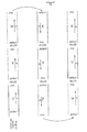
- FIG. 1 there is shown schematically an experimental sowing in two rows, seen from above.
- Each micro-plot is sown with a specific variety of seeds and is represented in the direction of sowing S by the letters U-V-W, X-Y-Z, W-U-V.
- Each micro-plot is separated from the next by a driveway.
- the variety of seeds is changed at each micro-plot so that each is sown with a different variety from the previous one, or from the one next to it.
- the length of micro-plots is 4 to 12 m, that of aisles from 0.40 to 1 m.
- the spacing between the two rows can be 0.60 to 0.80 m.
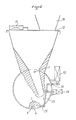
- a known pneumatic seed drill element essentially comprises a thin rotary disk 8, rotating in its vertical plane and having the perforations 1 on its periphery. The diameter and the number of perforations are different according to the species of seeds to be sown.
- the rotational movement of the disc 8 is communicated by the carrying wheels of the seed drill, by means of the shaft 11 a of an appropriate and adjustable transmission 11.
- the face 8c of the disc 8 is subjected to a vacuum on approximately 8/10 from its surface by a turbine 16 of the device.
- the opposite face 8d is, on a part, in contact with seeds 2 which are in a feed chamber 7 and which come, under the action of gravity, from a supply hopper 19 passing through a channel 6.
- the disc 8 has lugs 10 (not shown in Fig. 2) used to agitate the seeds in the bottom of the feed chamber 7 to avoid the settlement of said seeds produced by the rolling of the seed drill on the ground.
- the disc 8 in its rotation, transports in its circular trajectory the seeds 2 until a zone 17 without depression (visible only in fig. 3) where they are released then sown by a ploughshare on the ground (not shown).
- the face 8c of the disc 8 is covered by a suction casing 15, connected by a pipe 14 to the turbine of the device 16 which produces the vacuum.
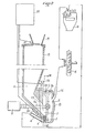
- the seeds arriving via the channel 6 coming from a hopper 13 are stored in the feed chamber 7 to be removed by the suction system by said sowing disc 8.
- a movable hatch 5 is arranged at the lower part of the supply chamber 7 and controls the access to an extraction pipe 4, connected to a reservoir 18 for receiving the excess seeds placed under vacuum by the turbine 16.
- the hopper 13 is closed at its upper part by a second hatch 12 serving as the bottom for a supply hopper 19.
- FIG. 4 being a horizontal schematic representation of the plots U and V of FIG. 1.
- the loading of the disc by the 2V seeds is then carried out according to the process described with reference to FIG. 3. Between the start of loading Dc and the end of loading Fc, the time necessary to cross the aisle elapses.
- the hatch 5 opens, for a time controlled by an electrical control system 20, under the action of an electromagnet for controlling the hatch 22, and levers 23, for sucking the excess seeds 2U, remaining in the chamber 7, through the piping 4, for then storing them in the receiving tank 18, thus recovering the excess seeds from one or more sowing elements.
- the sowing plate 8 of 6 or 8 cells rotates at high speed, driven by a multiplier 11, which allows the sowing of the seeds 2 remaining on the disc 8.
- the hatch 12 is opened which is controlled by the electromagnet 21 controlled by the electrical cabinet 20, which allows the filling of the supply chamber 7 with the seeds 2V prepared in the supply hopper 19 and passing through the supply channel 6: the cycle begins again for the new plot.
- the operations described above apply simultaneously to each sowing element in order to produce plots of one or more rows.
- the receiving tank 18 may comprise as many buckets as there are micro-plots to be sown, an automatic system causing said buckets to advance so that they each receive in turn the excess seeds.
Landscapes
- Life Sciences & Earth Sciences (AREA)
- Soil Sciences (AREA)
- Environmental Sciences (AREA)
- Sowing (AREA)
- Drilling And Boring (AREA)
Claims (5)
Priority Applications (1)
| Application Number | Priority Date | Filing Date | Title |
|---|---|---|---|
| AT83401536T ATE15744T1 (de) | 1982-07-29 | 1983-07-26 | Mehrzwecksaegeraet. |
Applications Claiming Priority (2)
| Application Number | Priority Date | Filing Date | Title |
|---|---|---|---|
| FR8213270A FR2530919B1 (fr) | 1982-07-29 | 1982-07-29 | Semoir a vidange pneumatique polyvalent pour semis d'experimentation et semis de culture |
| FR8213270 | 1982-07-29 |
Publications (2)
| Publication Number | Publication Date |
|---|---|
| EP0100723A1 EP0100723A1 (de) | 1984-02-15 |
| EP0100723B1 true EP0100723B1 (de) | 1985-09-25 |
Family
ID=9276455
Family Applications (1)
| Application Number | Title | Priority Date | Filing Date |
|---|---|---|---|
| EP83401536A Expired - Lifetime EP0100723B1 (de) | 1982-07-29 | 1983-07-26 | Mehrzwecksägerät |
Country Status (4)
| Country | Link |
|---|---|
| EP (1) | EP0100723B1 (de) |
| AT (1) | ATE15744T1 (de) |
| DE (1) | DE3360891D1 (de) |
| FR (1) | FR2530919B1 (de) |
Cited By (4)
| Publication number | Priority date | Publication date | Assignee | Title |
|---|---|---|---|---|
| WO2005011358A1 (en) * | 2003-08-05 | 2005-02-10 | John Holly | Seed distribution method and apparatus |
| US10257975B2 (en) | 2013-09-05 | 2019-04-16 | Kinze Manufacturing, Inc. | Multiple agricultural product application method and systems |
| US11770995B2 (en) | 2009-02-02 | 2023-10-03 | Deere & Company | Seeding machine with seed delivery system |
| US12514148B2 (en) | 2011-03-25 | 2026-01-06 | Deere & Company | Planting unit for a seeding machine having a seed meter and seed delivery system |
Families Citing this family (9)
| Publication number | Priority date | Publication date | Assignee | Title |
|---|---|---|---|---|
| DE3403540C1 (de) * | 1984-02-02 | 1985-07-25 | Amazonen-Werke H. Dreyer Gmbh & Co Kg, 4507 Hasbergen | Maschine zum dosierten Ausbringen von koernigem Material |
| GB8804660D0 (en) * | 1988-02-27 | 1988-03-30 | Massey Ferguson Mfg | Pneumatic drills & fertilizer spreaders |
| AU2006244254B2 (en) * | 2005-05-09 | 2012-02-02 | Monsanto Technology Llc | Custom planter and method of custom planting |
| US8371240B2 (en) | 2009-05-06 | 2013-02-12 | Agco Corporation | Twin row planter |
| US8336470B2 (en) * | 2009-05-06 | 2012-12-25 | Agco Corporation | Seed meter airflow cover |
| US8371239B2 (en) | 2009-05-06 | 2013-02-12 | Agco Corporation | Dual product dispensing disk for metering device |
| US8336469B2 (en) | 2009-05-06 | 2012-12-25 | Agco Corporation | Fertilizer transfer chamber for metering device |
| US8322293B2 (en) | 2009-05-06 | 2012-12-04 | Agco Corporation | Precision fertilizer placement |
| US9775279B2 (en) | 2014-05-09 | 2017-10-03 | Deere & Company | Seed valve and planting method for multiple seed types |
Family Cites Families (3)
| Publication number | Priority date | Publication date | Assignee | Title |
|---|---|---|---|---|
| FR2323308A1 (fr) * | 1975-02-28 | 1977-04-08 | Agronomique Inst Nat Rech | Semoir polyvalent de precision pour petites parcelles |
| FR2389316A1 (en) * | 1977-05-06 | 1978-12-01 | Hodee Mais Angevin | Experimental seed bed sowing machine - has individual cartridges mounted on slider to discharge into hopper which is emptied into collector at end of each row |
| FR2492623A1 (fr) * | 1980-10-29 | 1982-04-30 | Inst Tech Cereales Fourrages | Element semeur et semoir pour parcelles experimentales |
-
1982
- 1982-07-29 FR FR8213270A patent/FR2530919B1/fr not_active Expired
-
1983
- 1983-07-26 AT AT83401536T patent/ATE15744T1/de not_active IP Right Cessation
- 1983-07-26 EP EP83401536A patent/EP0100723B1/de not_active Expired - Lifetime
- 1983-07-26 DE DE8383401536T patent/DE3360891D1/de not_active Expired - Lifetime
Cited By (8)
| Publication number | Priority date | Publication date | Assignee | Title |
|---|---|---|---|---|
| WO2005011358A1 (en) * | 2003-08-05 | 2005-02-10 | John Holly | Seed distribution method and apparatus |
| US7490565B2 (en) | 2003-08-05 | 2009-02-17 | John Holly | Seed distribution method and apparatus |
| US11770995B2 (en) | 2009-02-02 | 2023-10-03 | Deere & Company | Seeding machine with seed delivery system |
| US11770994B2 (en) | 2009-02-02 | 2023-10-03 | Deere & Company | Seeding machine with seed delivery system |
| US11793104B2 (en) | 2009-02-02 | 2023-10-24 | Deere & Company | Seeding machine with seed delivery system |
| US11849665B2 (en) | 2009-02-02 | 2023-12-26 | Deere & Company | Seeding machine with seed delivery system |
| US12514148B2 (en) | 2011-03-25 | 2026-01-06 | Deere & Company | Planting unit for a seeding machine having a seed meter and seed delivery system |
| US10257975B2 (en) | 2013-09-05 | 2019-04-16 | Kinze Manufacturing, Inc. | Multiple agricultural product application method and systems |
Also Published As
| Publication number | Publication date |
|---|---|
| EP0100723A1 (de) | 1984-02-15 |
| DE3360891D1 (en) | 1985-10-31 |
| FR2530919A1 (fr) | 1984-02-03 |
| FR2530919B1 (fr) | 1985-10-04 |
| ATE15744T1 (de) | 1985-10-15 |
Similar Documents
| Publication | Publication Date | Title |
|---|---|---|
| EP0100723B1 (de) | Mehrzwecksägerät | |
| EP3813505B1 (de) | Anordnung zur ausgabe von granulatförmigen produkten | |
| EP0338883A1 (de) | Verteilervorrichtung an einer Einzelkornsämaschine | |
| FR2491040A1 (fr) | Appareil de distribution de composants de circuits electriques | |
| FR2531603A1 (fr) | Semoir en poquets | |
| EP0050829B1 (de) | Sägerät für Versuchsparzellen | |
| FR2574243A1 (fr) | Machine a semer des graines par exemple des graines d'ail | |
| EP0091863A1 (de) | Auslesevorrichtung für den Verteiler einer Einzelkornsämaschine | |
| FR2810633A1 (fr) | Appareil pour l'alimentation a une machine de cartonnage de rubans d'emballage du type blister | |
| EP1675734B1 (de) | Verfahren zur automatischen umhüllung von kleinen objekten, wie zum beispiel dokumenten, und zur durchführung desselben verwendete vorrichtung | |
| EP4262348B1 (de) | Maschine zum pflanzen von zwiebeln in einer vorbestimmten position | |
| US1604624A (en) | Planter | |
| FR2960122A1 (fr) | Machine a planter des rhizomes, et notamment des rhizomes de miscanthus | |
| EP1222845A1 (de) | Verfahren zum Trennen eckiger Setzlinge, Gerät zum Ausführen des Verfahrens und Pflanzmaschine mit einem solchen Gerät zum Pflanzen von Setzlingen | |
| FR2635432A1 (fr) | Distributeur de semoir de precision en au moins une ligne | |
| FR2643212A1 (fr) | Dispositif de reglage d'un distributeur pour semoir monograine | |
| CN116897660A (zh) | 一种农作物种苗连续零速投苗移栽机构及使用方法 | |
| FR2654071A1 (fr) | Appareil automatique comportant un dispositif unique de prehension pour structure separatrice ou alveolaire devant etre extraite, ouverte et introduite successivement dans des conteneurs ou cartons pour bouteilles et objets similaires. | |
| FR2543793A1 (fr) | Procede et dispositif pour introduire des plants sensiblement cylindrique dans un bac | |
| FR2738988A1 (fr) | Machine automatique permettant de realiser le depotage et rempotage de plants et dispositif permettant la manutention desdits plants utilisables sur une telle machine | |
| US2340240A (en) | Potato and bean planter | |
| EP0060753B1 (de) | Dosiergeräte zum Abfüllen von Füllgut in Behälter | |
| EP4371383A1 (de) | Mechanische sämaschine und verteilerblock für eine mechanische sämaschine | |
| BE895732A (fr) | Installation de remplissage de godets | |
| FR2712971A1 (fr) | Appareil de plantation d'objets dans le sol. |
Legal Events
| Date | Code | Title | Description |
|---|---|---|---|
| PUAI | Public reference made under article 153(3) epc to a published international application that has entered the european phase |
Free format text: ORIGINAL CODE: 0009012 |
|
| AK | Designated contracting states |
Designated state(s): AT BE CH DE FR GB IT LI LU NL SE |
|
| 17P | Request for examination filed |
Effective date: 19840114 |
|
| GRAA | (expected) grant |
Free format text: ORIGINAL CODE: 0009210 |
|
| AK | Designated contracting states |
Designated state(s): AT BE CH DE FR GB IT LI LU NL SE |
|
| REF | Corresponds to: |
Ref document number: 15744 Country of ref document: AT Date of ref document: 19851015 Kind code of ref document: T |
|
| PG25 | Lapsed in a contracting state [announced via postgrant information from national office to epo] |
Ref country code: SE Effective date: 19850930 |
|
| ITF | It: translation for a ep patent filed | ||
| REF | Corresponds to: |
Ref document number: 3360891 Country of ref document: DE Date of ref document: 19851031 |
|
| PLBE | No opposition filed within time limit |
Free format text: ORIGINAL CODE: 0009261 |
|
| STAA | Information on the status of an ep patent application or granted ep patent |
Free format text: STATUS: NO OPPOSITION FILED WITHIN TIME LIMIT |
|
| 26N | No opposition filed | ||
| REG | Reference to a national code |
Ref country code: FR Ref legal event code: TP |
|
| ITTA | It: last paid annual fee | ||
| PGFP | Annual fee paid to national office [announced via postgrant information from national office to epo] |
Ref country code: GB Payment date: 19920717 Year of fee payment: 10 Ref country code: CH Payment date: 19920717 Year of fee payment: 10 |
|
| PGFP | Annual fee paid to national office [announced via postgrant information from national office to epo] |
Ref country code: AT Payment date: 19920722 Year of fee payment: 10 |
|
| PGFP | Annual fee paid to national office [announced via postgrant information from national office to epo] |
Ref country code: FR Payment date: 19920728 Year of fee payment: 10 |
|
| PGFP | Annual fee paid to national office [announced via postgrant information from national office to epo] |
Ref country code: LU Payment date: 19920730 Year of fee payment: 10 |
|
| PGFP | Annual fee paid to national office [announced via postgrant information from national office to epo] |
Ref country code: NL Payment date: 19920731 Year of fee payment: 10 |
|
| PGFP | Annual fee paid to national office [announced via postgrant information from national office to epo] |
Ref country code: DE Payment date: 19920825 Year of fee payment: 10 |
|
| PGFP | Annual fee paid to national office [announced via postgrant information from national office to epo] |
Ref country code: BE Payment date: 19920903 Year of fee payment: 10 |
|
| EPTA | Lu: last paid annual fee | ||
| PG25 | Lapsed in a contracting state [announced via postgrant information from national office to epo] |
Ref country code: LU Free format text: LAPSE BECAUSE OF NON-PAYMENT OF DUE FEES Effective date: 19930726 Ref country code: GB Effective date: 19930726 Ref country code: AT Effective date: 19930726 |
|
| PG25 | Lapsed in a contracting state [announced via postgrant information from national office to epo] |
Ref country code: LI Effective date: 19930731 Ref country code: CH Effective date: 19930731 Ref country code: BE Effective date: 19930731 |
|
| BERE | Be: lapsed |
Owner name: LACAILLE S.A. Effective date: 19930731 |
|
| PG25 | Lapsed in a contracting state [announced via postgrant information from national office to epo] |
Ref country code: NL Effective date: 19940201 |
|
| NLV4 | Nl: lapsed or anulled due to non-payment of the annual fee | ||
| GBPC | Gb: european patent ceased through non-payment of renewal fee |
Effective date: 19930726 |
|
| PG25 | Lapsed in a contracting state [announced via postgrant information from national office to epo] |
Ref country code: FR Effective date: 19940331 |
|
| REG | Reference to a national code |
Ref country code: CH Ref legal event code: PL |
|
| PG25 | Lapsed in a contracting state [announced via postgrant information from national office to epo] |
Ref country code: DE Effective date: 19940401 |
|
| REG | Reference to a national code |
Ref country code: FR Ref legal event code: ST |