EP0100778A1 - Dispositif pour changer automatiquement la plaque d'impression - Google Patents
Dispositif pour changer automatiquement la plaque d'impression Download PDFInfo
- Publication number
- EP0100778A1 EP0100778A1 EP82107255A EP82107255A EP0100778A1 EP 0100778 A1 EP0100778 A1 EP 0100778A1 EP 82107255 A EP82107255 A EP 82107255A EP 82107255 A EP82107255 A EP 82107255A EP 0100778 A1 EP0100778 A1 EP 0100778A1
- Authority
- EP
- European Patent Office
- Prior art keywords
- plate
- printing
- claw
- section
- printing cylinder
- Prior art date
- Legal status (The legal status is an assumption and is not a legal conclusion. Google has not performed a legal analysis and makes no representation as to the accuracy of the status listed.)
- Granted
Links
- 238000007639 printing Methods 0.000 title claims abstract description 83
- 230000000694 effects Effects 0.000 claims abstract description 3
- 210000000078 claw Anatomy 0.000 description 56
- 230000033001 locomotion Effects 0.000 description 5
- 238000000034 method Methods 0.000 description 3
- 230000008878 coupling Effects 0.000 description 2
- 238000010168 coupling process Methods 0.000 description 2
- 238000005859 coupling reaction Methods 0.000 description 2
- 238000011084 recovery Methods 0.000 description 2
- 230000000630 rising effect Effects 0.000 description 2
- 230000005540 biological transmission Effects 0.000 description 1
- 238000010276 construction Methods 0.000 description 1
- 230000000149 penetrating effect Effects 0.000 description 1
- 238000002360 preparation method Methods 0.000 description 1
Images







Classifications
-
- B—PERFORMING OPERATIONS; TRANSPORTING
- B41—PRINTING; LINING MACHINES; TYPEWRITERS; STAMPS
- B41F—PRINTING MACHINES OR PRESSES
- B41F27/00—Devices for attaching printing elements or formes to supports
- B41F27/12—Devices for attaching printing elements or formes to supports for attaching flexible printing formes
- B41F27/1206—Feeding to or removing from the forme cylinder
Definitions
- the present invention relates to an automatic exchange system for a plate in a printing machine.
- printing sections in paper working machines are classified into two types of an upper printing type and a lower printing type, and in either type, mounting and dismounting of a plate sheet onto and from a printing cylinder have been carried out entirely through a manual operation, after a space for mounting a plate sheet (3) onto a printing cylinder (4) has been established by separating a printing section (2) and a paper feed section (2a) from a paper eject section (1) as shown in Fig. 1 which illustrates one example of the upper printing system in the prior art. The outline of this working procedure will be explained in the following.
- a more specific object of the present invention is to provide an automatic printing plate exchange system in which a time required for set up can be greatly shortened, hence a productivity is enhanced by the corresponding amount, and thereby labor saving and safety can be improved.
- an automatic printing plate exchange system comprising plate holding means adapted to be mounted to a printing plate while presenting a resilient effect as a whole and having anchor-shaped engaging sections along its front and rear edgen, send-out means for sequentially sending out plates which have been preliminarily arrayed in a predeter- minet order, up to a predetermined position, conveyor means fo receiving the plate sent out from said send-out means by with the anchor-shaped engaging section of said plate holding means and conveying the plate up to a predetermined position above a printing section, a printing cylinder on which said plate can be mounted, and delivery means for receiving the plate from the conveying means by engaging with the anchor-shaped engaging section and delivering the plate to said printing cylinder.
- the automatic printing plate exchange system is constructed in the above- featured manner, plate sheets to be exchanged sequentially can be preset preliminarily at any desired place outside of the printing machine in a cartridge-like fashion, and the preset plate sheet can be automatically mounted and dismounted in a predetermined sequence onto and from the printing cylinder with the aid of hydraulic cylinders by merely operating push-buttons.
- Fig. 4 is a perspective view showing the state of a plate sheet (3) in the prior art having special fixture jigs attached thereto for the purpose of automatically mounting and dismounting a printing plate onto and from a printing cylinder in an automatic printing plate exchange system according to one preferred embodiment of the present invention.
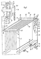
- Fig. 5 shows a preset apparatus (16) for preliminarily accommodating plate sheets (3) in a correct order according to the scheduled sequence of use on that day.
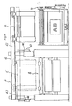
- Fig. 6 shows a plate conveyor apparatus (41) for conveying plate sheets (3) successively from the preset apparatus (16) to a plate exchange apparatus (18). It is to be noted that in Fig. 6 the left hand plate carrier (17) is shown in cross-section taken along line B-B in Fig. 7.
- Fig. 7 is a side view of the plate conveyor apparatus (41)
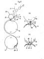
- Fig. 8(a) is a cross-section front view of the plate exchange apparatus (18)
- Fig. 8(b) is a cross-section view taken along line D-D in Fig. 8(a).
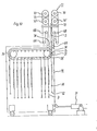
- Fig. 9 is a front view of an automatic printing plate exchange system comprising the plate exchange apparatus (18), the plate conveyor apparatus (41) and the preset apparatus (16).
- Fig. 10 is a schematic side view showing the state where a plate sheet (3) is being sent from the plate carrier (17) to the preset apparatus
- F ig. 11 is a schematic side view showing the state where a plate sheet (3) is being sent from the preset apparatus (16) to the plate carrier (17).
- the illustrated system is composed of the plate sheet (3) having special jigs, the plate preset apparatus (16), the plate carrier (17) and the plate exchange apparatus (18) as shown in Fig. 9.
- a fixture jig (14) to be fittingly engaged with a front fixture strip (6) of a plate sheet (3) in the prior art is connected to a rubber belt (13), and the other end of the rubber belt (13) is connected to andther fixture jig (12) having an anchor-shaped protrusion.
- a rear fixture strip (7) of the plate sheet (3) is fittingly engaged with a fixture jig (15) having an anthor-shaped protrusion similar to the above-described facture jig (12).
- the preset apparatus is made to be movable by mounting casters at four corners of its bottom surface as.shown in Fig. 5.
- a U-shaped handle (20) At the center of the side surface of its lower horizontal frame is mounted a U-shaped handle (20), and a hook (22) mounted at a front end of a piston rod of a cylinder (21) is detachably coupled to a horizontal member (20') of the U-shaped handle (20).
- the cylinder (21) pivotably supported by a support member (24).
- sprockets (26) and (26') are rotatably supported shafts (25) and (25'), and on these shafts are mounted sprockets (26) and (26'), respectively.
- a one-way clutch (27) is mounted on the shaft (25 1 ), and a sprocket (36) is fixedly secured to the side surface of the one-way clutch (27).
- the sprocket (26) mounted on the rotary shaft (25) is coupled to the sprocket (26 1 ) via a chain (29).
- a V-shaped beam (31) for suspending the plate sheet (3) is rotatably mounted at one end of a special attachment (30) provided on the chain (29), and a cam follower (32) is mounted at the other end thereof.
- the cam follower (32) is interposed between rails (33) and (33 ! ) provided in parallel to each other on the inside surface of a side frame (110) of the preset apparatus (16).
- another sprocket is rotatably provided on the same side frame (110) at a position right under the shaft (25'), and this sprocket (34) is coupled to the above-described sprocket (36) via a chain (35).
- Reference numeral (38) designates a cylinder provided on the side frame (110), and a rod end of this cylinder (38) is coupled to the chain (35) at a point a in Fig. 5 so that the sprocket (36) can be rotated by actuating the cylinder (38).
- the bottom end of the cylinder (38) is fixed to the side frame (110) via a support member (40).
- the sprocket (26') is rotated in one direction by a predetermined angle via the one-way clutch (27).
- the plate conveyor apparatus (41) consists of a track elevator (42) and a plate conveying carrier (17).
- Reference numeral (43) designates a track, which is suspended from one ends of inverse L-shaped beams (44) and (44').
- Vertical portions (44") of the inverse L-shaped beams (44) and (44') are slidably fitted in support beams (45) provided on the top surface of a frame (79) of the printing section (2).
- a piston rod (47) of a cylinder (48) is coupled to a pin (46) provided on the side surface of the inverse L-shaped beam (44), and the cylinder (48) is fixedly secured to the side surface of the support beam (45).
- racks (49) fixedly secured to other side surfaces of the support beams (45) mesh with pinions (51) and (51') provided at the opposite ends of a shaft (50) which is pivotably supported between the inverse L-shaped beams (44) and (44').
- wheels (53) rotatably mounted to a U-shaped frame (52) make contact with inside surfaces of flange portions of the track (43) having an I-shaped cross-section so that the carrier (17) can travel along the track (43).
- a rack (54) On the bottom surface of the flange portions of the track (43) is fixedly secured a rack (54), and a pinion (55) is disposed at a position adapted to mesh with the rack (54).
- a motor (56) coupled to the pinion (55) is fixedly secured to a bottom plate (57) of the U-shaped frame (52).
- a fulcrum (58) at the center of the bottom surface of the'U-shaped frame (52) is provided a fulcrum (58), and a frame (59) is rotatably mounted at the fulcrum (58).
- rotary drive shafts (61) and (61') are connected to drive motors (62) and (62'), respectively, and the other ends are connected via universal joints (63) and (63') to rotary drive shafts (64) and (64') of the adjacent carrier (17').
- sprockets (68), (69), (70), (70') and (71) are coupled through chains (72) and (72'), respectively.
- an upper claw (73) is mounted on the chains (72)
- a lower claw (74) is mounted on the chains (72')
- these claws (73) and (74) has a configuration adapted to engage with the anchor-shaped protrusions (12') and (15')', respective-. ly, of the fixture jigs (12) and (15) of the plate sheet (3).
- the plate carrier (17) on the left hand in Fig. 6 is shown in cross-section taken along line B-B in Fig. 7, and the piston rod (66) of the cylinder (65) is shown in a retracted state.
- the plate carrier (17') on the right hand in Fig. 6 is shown as viewed in the direction of arrow C in Fig. 7.
- the plate exchange apparatus (18) is constructed of a feed-in cam device (75), a receiving roll (76), a printing cylinder (77) and a driving device (78) for the respective devices.
- a cam shaft (80) On a frame (79) of a printing section (2) is rotatably mounted a cam shaft (80) and on this shaft are mounted a plurality of claws (83) each consisting of a rear edge claw (81) and a front edge claw (82).
- a gear (84) At one end of the cam shaft (80) is provided a gear (84), and a gear (85) meshed with the gear (84) is coupled via a coupling member (86) to a motor (87).
- the motor (87) is fixed on the frame (79) by the intermediary of a support base (88).
- a pulse generator (89) for detecting an angular position of the cam shaft (80).
- the receiving roll (76) is supported between the frames (79) in parallel to the cam shaft (80), and its axial end portions (76 1 ) are rotatably supported by eccentric bearings (90), which are in turn rotatably mounted to the frames (79). Furthermore, the eccentric bearings (90) are engraved into sector gears (91), and the sector gears (91) are meshed with pinions (93) provided on the opposite end portions of a pinion shaft (92) which is pivotably mounted in parallel to the receiving roll (76).
- One axial end of the pinion shaft (92) is coupled via a coupling member (94) to a motor (95).
- a pulse generator (96) for detecting an angular position of the pinion shaft (92).
- the gap space between the receiving roll (76) and the printing cylinder (77) can be adjusted by the rotation of the motor (95).
- a gear (97) At one axial end of the receiving roll (76) is mounted a gear (97), and another gear (98) meshed with the gear (97) is coupled via a clutch (99) to a motor (100).
- This motor (100) is fixed to the frame (79) via the support base (88).
- a pulse generator (101) for detecting an angular position of the receiving roll (76).
- the outer circumferential length of the receiving roll (76) is equal to the total length of the plate sheet (3) and the associated fixture jigs (12), (13), (14) and (15), and the receiving roll (76) would rotate one revolution for one revolution of rotation of the printing cylinder (77).
- a claw belt (102) having an anchor-shaped cross-section, and this anchor-shape is such configuration that can be engaged with the fixture jigs (12) and (15) of the plate sheet (3).
- the printing cylinder (77) is pivotably mounted in parallel to the receiving roll (76) and rotatably supported by the frames (79).
- the axial end portion of the printing cylinder (77) rotatably supports a gear (102') and a rotor section (103') of a clutch (103).
- the rotor section (103') is connected to the gear (102') and an armature section (103") of the clutch (103) is fixedly engaged with the axial end portion of the printing cylinder (77). Accordingly, engagement and disengagement of a drive force transmission system from the printing cylinder (77) to the receiving roll shaft (76) are possible.
- a pulse generator (104) for detecting an angular position of the printing cylinder.
- a gear (105) meshing with the above-described gear (105) is rotatably mounted on.the frame (79), and is also connected to a motor (107) via a clutch (106).
- the motor (107) is fixed to the frame (79) by the intermediary of a support member (108).
- a slot having a cross-section shape that can be engaged with the protrusions (12") and (15") of the plate fixture jigs (12) and (15).
- the V-shaped beam (31) is standing by at the position marked (i) in Fig. 10, and when the drive motors (62) and (62') in the plate carrier (17) begin to rotate simultaneously, the upper claw (73) and the lower claw (74) holding the plate sheet (3) are both lowered, and the plate sheet (3) is also lowered.
- the low claw (74) passes by the left side of the sprocket (69)
- the low claw (74) is disengaged from the plate fixture jig "(12) and continues to move in itself, and at the time point when it passes along the sprocket ' (69) in the rightward direction, it stops there in a standby state.
- the preset apparatus (16) placed at the position shown in Fig. 10 is moved to the position shown in Fig. 11 by the retracting operation of the cylinder (21), and at the same time, the V-shaped beams (31) having the plate sheet (3) suspended therefrom is moved up to the position marked (j) in Fig. 11 by reciprocating movement of the cylinder (38), and is held at that position.
- the plate sheet (3) is prevented from being displaced when the plate carrier (17) moves from the preset apparatus (16) to the plate exchange apparatus (18). Then, the air cylinder (65) is again actuated, so that the sprocket (69) moves from the position shown by double-dot chain lines in Fig. 11 to the position shown by solid lines.
- the receiving roll (76) and the printing cylinder (77) are simultaneously rotated by the motor (100) until they reach the angular positions shown in Fig. 12(c).
- the clutch (103) is connected to the gear (102'), the clutch (106) is opened, and the clutch (99) is kept in a connected state.
- the receiving roll (76) is raised from the position shown by solid lines to the position shown by double-dot chain lines in Fig. 12(c) by actuating the motor (95) to rotate the eccentric gear (90) via the pinion (93).
- the receiving roll (76) is lowered through an operation in the opposite direction to'that when the remaining roll (76) was raised.
- the clutch (103) and the clutch (106) are both in an opened state, while the clutch (99) is held connected.
- the position of the receiving roll (76) at this time is shown by dash lines in Fig. 12 (c) .
- the motor (100) is actuated to rotate only the receiving roll (76) in the clockwise direction as viewed in Fig. 12 until the receiving roll (76) reaches the position shown by double-dot chain lines in Fig. 12(b). Furthermore, when the receiving roll (76) has been raised by actuating the motor (95), the receiving roll takes the state shown by solid lines in Fig. 12(b), and so, the rear plate fixture jig (15) can be completely disengaged from the protrusion of the slot (109) on the printing cylinder (77).
- the clutch (103) is connected to the gear (102'), the clutch (106) is opened, and while the clutch (99) is kept connected, the motor (100) is again actuated to rotate the receiving roll (76) and the printing cylinder (77) .simultaneously, and when the claw belt (102) has reached the position shown in Fig. 12(a), the motor (100) is stopped.
- the cam shaft (80) has been retired from the position shown by solid lines to the position shown by double-dot chain lines in Fig. 12(a) by actuating the motor (87).
- the claw (81) for the rear end which has been retired to the position shown by double-dot chain lines is rotated in the clockwise direction as viewed in Fig. 12 at a circumferential speed equal to the outer circumferential speed of the receiving roll (76) by actuating the motor (87).
- the receiving roll (76) and the printing cylinder (77) are started to rotate in the direction of arrows in Fig. 12(a) by actuating the motor (100).
- the upper claw (73) which has been placed at the position (q) in Fig. 12(a) is rotated in the clockwise direction as viewed in Fig. 12 at the same circumferential speed as that of the outer circumferential surface of the receiving roll (76) by actuating the motor (87), and at the moment when the upper claw (73) has engaged with the above-described rear fixture jig (15) at the position (r), the receiving roll (76) and the printing cylinder (77) which have been held stopped by that moment, are started to rotate at the same circumferential speed, hence the rear fixture jig (15) is disengaged from the claw (81) for the rear end on the cam shaft (80), and it begins to rise along the chain (72) of the carrier (17').
- the claw (81) for the rear end which has been disengaged from the rear fixture jig (15) is standing by at the positions (81')-(82') shown by double-dot chain lines in Fig. 13 (a) after it has been rotated in the anti-clockwise direction as viewed in Fig. 13 by actuating the motor (87), in preparation for next engagement with the front fixture jig (12).
- the claw belt (102) of the receiving roll (76) which has been disengaged from the rear fixture jig (15), rotates in synchronism with the movement of the printing cylinder (77) which is rotating as engaged with the front fixture jig (12) of the plate sheet (3), and at the time point when the claw belt (102) has reached the position (S) in Fig. 13 (b), the motors (87) and (100) are stopped, and hence, movement of the claw belt (102) is also stopped.
- the claw belt (102) which was disengaged from the front fixture jig (12) is stopped when it has reached the position shown by double-dot chain lines in Fig. 13(a).
- the rear claw (74) is rotated in the clockwise direction as viewed in Fig. 13 from the position marked (t) to.the position marked (u) in Fig. 13(a) by actuating the motor (62'), and after it has stopped there it stands by.
- the rear claw (74) begins to rise by actuating the motor (62') again, as a result the engagement between the front fixture jig (12) and the front end claw (82) is released, and the front fixture jig (12) rises jointly with the rear claw (74) as engaged therewith.
- the claw (82) for the front end which has disengaged from the front fixture jig (12) continues to rotate by 180° in the anti-clockwise direction as viewed in Fig. 13, and thereafter stops to stand by for the next mounting operation of the plate sheet (3).
- both the upper claw (73) and the lower claw (74) which are rising jointly with the plate sheet (3) would stop at the time point when the upper claw (73) has reached its upper limit, and then the recovery of the used plate sheet (3) has been completed.
- the automatic printing plate exchange system is constructed as described above, as compared to the manual operation system in the prior art it becomes unnecessary to open the frames of the printing section and the paper feed section for the purpose of reserving a working space each time the printing plate is to be exchanged.
- the plate sheets can be preset outside of the printing machine, and moreover, if the printing machine is coupled to a plate storage instead of the preset apparatus and the works of exchanging the plates, storing them in the plate storage, etc. are controlled by a microcomputer, then it is possible to expand the printing machine into one printing system.
Landscapes
- Supply, Installation And Extraction Of Printed Sheets Or Plates (AREA)
Priority Applications (3)
| Application Number | Priority Date | Filing Date | Title |
|---|---|---|---|
| DE1982107255 DE100778T1 (de) | 1982-08-10 | 1982-08-10 | Vorrichtung zum automatischen auswechseln von druckplatten. |
| EP19820107255 EP0100778B1 (fr) | 1982-08-10 | 1982-08-10 | Dispositif pour changer automatiquement la plaque d'impression |
| DE8282107255T DE3271652D1 (en) | 1982-08-10 | 1982-08-10 | Automatic printing plate exchange system |
Applications Claiming Priority (1)
| Application Number | Priority Date | Filing Date | Title |
|---|---|---|---|
| EP19820107255 EP0100778B1 (fr) | 1982-08-10 | 1982-08-10 | Dispositif pour changer automatiquement la plaque d'impression |
Publications (2)
| Publication Number | Publication Date |
|---|---|
| EP0100778A1 true EP0100778A1 (fr) | 1984-02-22 |
| EP0100778B1 EP0100778B1 (fr) | 1986-06-11 |
Family
ID=8189172
Family Applications (1)
| Application Number | Title | Priority Date | Filing Date |
|---|---|---|---|
| EP19820107255 Expired EP0100778B1 (fr) | 1982-08-10 | 1982-08-10 | Dispositif pour changer automatiquement la plaque d'impression |
Country Status (2)
| Country | Link |
|---|---|
| EP (1) | EP0100778B1 (fr) |
| DE (2) | DE3271652D1 (fr) |
Cited By (3)
| Publication number | Priority date | Publication date | Assignee | Title |
|---|---|---|---|---|
| EP0623467A1 (fr) * | 1993-03-25 | 1994-11-09 | MAN Roland Druckmaschinen AG | Dispositif de remplacement automatique des plaques d'impression dans des machines offset pour imprimer des feuilles avec plusieurs groupes d'impression |
| DE3844946C2 (de) * | 1988-11-09 | 1997-05-15 | Roland Man Druckmasch | Rotationsdruckmaschine mit einer Vorrichtung zur Zuführung eines Druckbildträgers zum Druckformzylinder |
| DE10220424A1 (de) * | 2001-12-11 | 2003-06-18 | Swisslog Telelift Gmbh | Verfahren und Vorrichtung zur automatischen Druckplattenübergabe |
Families Citing this family (7)
| Publication number | Priority date | Publication date | Assignee | Title |
|---|---|---|---|---|
| JPH0723259Y2 (ja) * | 1987-12-01 | 1995-05-31 | 三菱重工業株式会社 | 輪転印刷機の駆動装置 |
| DE3940449A1 (de) * | 1989-12-07 | 1991-06-13 | Roland Man Druckmasch | Handhabungsvorrichtung |
| DE4003445A1 (de) * | 1990-02-06 | 1991-08-08 | Roland Man Druckmasch | Automatisches plattenzufuehr- und zylinderbeschickungssystem |
| DE4024061C2 (de) * | 1990-07-28 | 1994-02-10 | Krause Biagosch Gmbh | Verfahren und Vorrichtung zur Produktivitätssteigerung von Rotationsdruckmaschinen |
| DE69212030T2 (de) * | 1991-03-08 | 1996-11-28 | Fuji Photo Film Co Ltd | Halter für Druckplatten, Verfahren und Vorrichtung zum Positionieren dieses Halters |
| DE4342359C1 (de) * | 1993-12-11 | 1995-06-22 | Roland Man Druckmasch | Magazin für den automatischen Druckplattenwechsel |
| DE102008001715B4 (de) | 2008-05-13 | 2011-07-14 | KOENIG & BAUER Aktiengesellschaft, 97080 | Zylinder einer Rotationsdruckmaschine |
Citations (2)
| Publication number | Priority date | Publication date | Assignee | Title |
|---|---|---|---|---|
| US3828672A (en) * | 1972-10-17 | 1974-08-13 | American Bank Note Co | Apparatus for fitting flexible printing plates and rigging to printing press cylinders |
| US4178848A (en) * | 1976-06-14 | 1979-12-18 | Ryobi Ltd. | Automatic plate supplying device for use in an offset printing machine |
-
1982
- 1982-08-10 DE DE8282107255T patent/DE3271652D1/de not_active Expired
- 1982-08-10 DE DE1982107255 patent/DE100778T1/de active Pending
- 1982-08-10 EP EP19820107255 patent/EP0100778B1/fr not_active Expired
Patent Citations (2)
| Publication number | Priority date | Publication date | Assignee | Title |
|---|---|---|---|---|
| US3828672A (en) * | 1972-10-17 | 1974-08-13 | American Bank Note Co | Apparatus for fitting flexible printing plates and rigging to printing press cylinders |
| US4178848A (en) * | 1976-06-14 | 1979-12-18 | Ryobi Ltd. | Automatic plate supplying device for use in an offset printing machine |
Cited By (3)
| Publication number | Priority date | Publication date | Assignee | Title |
|---|---|---|---|---|
| DE3844946C2 (de) * | 1988-11-09 | 1997-05-15 | Roland Man Druckmasch | Rotationsdruckmaschine mit einer Vorrichtung zur Zuführung eines Druckbildträgers zum Druckformzylinder |
| EP0623467A1 (fr) * | 1993-03-25 | 1994-11-09 | MAN Roland Druckmaschinen AG | Dispositif de remplacement automatique des plaques d'impression dans des machines offset pour imprimer des feuilles avec plusieurs groupes d'impression |
| DE10220424A1 (de) * | 2001-12-11 | 2003-06-18 | Swisslog Telelift Gmbh | Verfahren und Vorrichtung zur automatischen Druckplattenübergabe |
Also Published As
| Publication number | Publication date |
|---|---|
| DE3271652D1 (en) | 1986-07-17 |
| DE100778T1 (de) | 1984-05-24 |
| EP0100778B1 (fr) | 1986-06-11 |
Similar Documents
| Publication | Publication Date | Title |
|---|---|---|
| US4408530A (en) | Automatic printing plate exchange system | |
| EP0100778B1 (fr) | Dispositif pour changer automatiquement la plaque d'impression | |
| EP0100779B1 (fr) | Dispositif pour changer la plaque d'impression | |
| DE102004027949B4 (de) | Vorrichtung zum Herstellen eines Bandes von etikettierten Behältern aus einer erwärmten thermoplastischen Kunststofffolie | |
| WO2015024681A2 (fr) | Procédé de transport de clichés lors du changement de clichés, et imprimante pourvue d'une tour d'impression et d'un dispositif de stockage à mobilité verticale | |
| EP0258442B1 (fr) | Dispositif de positionnement de tetes | |
| US4417514A (en) | Printing plate exchange system | |
| CN208812702U (zh) | 一种油墨盒可调节的柔性印刷机 | |
| CN112026370B (zh) | 一种用于硬纸板有色凹痕打印的设备 | |
| CN111232717B (zh) | 带状薄片材料加工成型用换卷及牵引装置 | |
| DE1298301B (de) | Einrichtung zum Abtrennen des untersten Diapappraehmchens von einem vertikalen Stapel horizontal liegender Raehmchen in einer Rahmungsmaschine | |
| DE2543460A1 (de) | Rollenschlitzmaschine | |
| CN108273906B (zh) | 一种风机筒体自动翻边打孔机 | |
| EP3036106B1 (fr) | Procédé de changement de clichés et presses à imprimer dotées d'une tour d'impression et d'un dispositif de stockage à mobilité verticale | |
| CN214086593U (zh) | 一种蛋挞出料装置 | |
| JPS62221542A (ja) | 刷版案内装置 | |
| CN113666160A (zh) | 一种模具生产用菲林片定位装置 | |
| CN108974505B (zh) | 一种用于包装袋折叠机的卷袋传输装置 | |
| JPH0211428B2 (fr) | ||
| JP2700364B2 (ja) | 印刷機の刷版交換装置 | |
| US20090025593A1 (en) | Printing press | |
| CN213894283U (zh) | 工件转移装置以及应用该工件转移装置的工件输送装置 | |
| CN211254471U (zh) | 自动拆垛搬运装置 | |
| CN118706377B (zh) | 一种汽车零部件检测装置及方法 | |
| CN222312184U (zh) | 一种热熔胶复合装置换卷机构 |
Legal Events
| Date | Code | Title | Description |
|---|---|---|---|
| PUAI | Public reference made under article 153(3) epc to a published international application that has entered the european phase |
Free format text: ORIGINAL CODE: 0009012 |
|
| AK | Designated contracting states |
Designated state(s): CH DE FR GB IT LI NL |
|
| ITCL | It: translation for ep claims filed |
Representative=s name: SOCIETA' ITALIANA BREVETTI S.P.A. |
|
| EL | Fr: translation of claims filed | ||
| TCNL | Nl: translation of patent claims filed | ||
| DET | De: translation of patent claims | ||
| 17P | Request for examination filed |
Effective date: 19840319 |
|
| GRAA | (expected) grant |
Free format text: ORIGINAL CODE: 0009210 |
|
| AK | Designated contracting states |
Kind code of ref document: B1 Designated state(s): CH DE FR GB IT LI NL |
|
| REF | Corresponds to: |
Ref document number: 3271652 Country of ref document: DE Date of ref document: 19860717 |
|
| ET | Fr: translation filed | ||
| ITF | It: translation for a ep patent filed | ||
| PLBE | No opposition filed within time limit |
Free format text: ORIGINAL CODE: 0009261 |
|
| STAA | Information on the status of an ep patent application or granted ep patent |
Free format text: STATUS: NO OPPOSITION FILED WITHIN TIME LIMIT |
|
| 26N | No opposition filed | ||
| ITTA | It: last paid annual fee | ||
| PGFP | Annual fee paid to national office [announced via postgrant information from national office to epo] |
Ref country code: NL Payment date: 19950825 Year of fee payment: 14 |
|
| PG25 | Lapsed in a contracting state [announced via postgrant information from national office to epo] |
Ref country code: NL Effective date: 19970301 |
|
| NLV4 | Nl: lapsed or anulled due to non-payment of the annual fee |
Effective date: 19970301 |
|
| PGFP | Annual fee paid to national office [announced via postgrant information from national office to epo] |
Ref country code: DE Payment date: 20010806 Year of fee payment: 20 |
|
| PGFP | Annual fee paid to national office [announced via postgrant information from national office to epo] |
Ref country code: GB Payment date: 20010808 Year of fee payment: 20 |
|
| PGFP | Annual fee paid to national office [announced via postgrant information from national office to epo] |
Ref country code: FR Payment date: 20010810 Year of fee payment: 20 |
|
| PGFP | Annual fee paid to national office [announced via postgrant information from national office to epo] |
Ref country code: CH Payment date: 20010815 Year of fee payment: 20 |
|
| REG | Reference to a national code |
Ref country code: GB Ref legal event code: IF02 |
|
| PG25 | Lapsed in a contracting state [announced via postgrant information from national office to epo] |
Ref country code: LI Free format text: LAPSE BECAUSE OF EXPIRATION OF PROTECTION Effective date: 20020809 Ref country code: GB Free format text: LAPSE BECAUSE OF EXPIRATION OF PROTECTION Effective date: 20020809 Ref country code: CH Free format text: LAPSE BECAUSE OF EXPIRATION OF PROTECTION Effective date: 20020809 |
|
| REG | Reference to a national code |
Ref country code: CH Ref legal event code: PL |
|
| REG | Reference to a national code |
Ref country code: GB Ref legal event code: PE20 Effective date: 20020809 |