EP0100799A1 - Hydraulischer Luftkompressor - Google Patents
Hydraulischer Luftkompressor Download PDFInfo
- Publication number
- EP0100799A1 EP0100799A1 EP82304298A EP82304298A EP0100799A1 EP 0100799 A1 EP0100799 A1 EP 0100799A1 EP 82304298 A EP82304298 A EP 82304298A EP 82304298 A EP82304298 A EP 82304298A EP 0100799 A1 EP0100799 A1 EP 0100799A1
- Authority
- EP
- European Patent Office
- Prior art keywords
- water
- air
- chamber
- hydraulic
- air compressor
- Prior art date
- Legal status (The legal status is an assumption and is not a legal conclusion. Google has not performed a legal analysis and makes no representation as to the accuracy of the status listed.)
- Withdrawn
Links
Images
Classifications
-
- F—MECHANICAL ENGINEERING; LIGHTING; HEATING; WEAPONS; BLASTING
- F03—MACHINES OR ENGINES FOR LIQUIDS; WIND, SPRING, OR WEIGHT MOTORS; PRODUCING MECHANICAL POWER OR A REACTIVE PROPULSIVE THRUST, NOT OTHERWISE PROVIDED FOR
- F03B—MACHINES OR ENGINES FOR LIQUIDS
- F03B13/00—Adaptations of machines or engines for special use; Combinations of machines or engines with driving or driven apparatus; Power stations or aggregates
Definitions
- This invention relates to a hydraulic air compressor.
- the invention relates to a hydraulic air compressor in which a gas can be compressed to a desired pressure at the temperature of the water used in the compressor.
- the energy of the compressed air can be put to a variety of uses.
- Hydraulic air compressors are veil known and have been used on a substantial scale in the past to compress air using the energy possessed by a head of water (under pressure).
- the excess of mass per unit volume of water in the down pipe of the compressor over the mass per unit volume of water in the tail race, or 'up pipe' is critical in the determination of the water velocity, since the drive head varies in accordance with the degree to which air has been entrained in the falling column of water.
- the invention provides a hydraulic air compressor having a drive and compression down pipe, an air inclusion chamber at the head of the down pipe arranged to be fed with water from a water source, an air separating chamber at the bottom of the down pipe, an air pipe leading from the separating chamber, an upwardly directed water return pipe leading from the separating chamber, means at the exit of the return pipe for pressurising water flowing from the return pipe and for directing the water into the air inclusion chamber when the air inclusion chamber is not fed with water from the water source the air inclusion chamber being arranged so that water enters it in a vortex and so that a venturi effect is created in the water stream and having an air inlet arranged so that, in use, air is drawn into the air inclusion chamber as a result of the vortical motion of the water; the venturi effect due to the velocity of the issuing jet, the inertia of which, permits the introduction of air into the air inclusion chamber at pressures higher than atmospheric.
- the air inclusion chamber tapers downwardly and includes a double wall with a gap between the walls, the gap being open at the bottom of the chamber, air inlet communicating with the gap, and tangential inlet or inlets to the tcp of the chamber for the introduction of water flowing from the water source or from the pressurising means, as the case may be.
- the compressor will serve to provide a supply of gas compressed by a liquid to the hydrostatic head at the point of separation when the temperatures of the gas will be that of the liquid. If the water source is not able to supply water at a sufficient head to maintain the supply of compressed air, then the pressurising means will be actuated to ensure that an adequate flow of water to the air inclusion chamber is provided.
- the compressed air is fed directly to the combustion chamber of a gas turbine or ram jet, so that no filters or turbine powered compressor stage is required.
- the compressed air from the hydraulic air compressor is fed to the chambers of a pneumatic displacement pump.
- the pump may be arranged to inject water into the combustion chamber of a gas turbine.
- the pump can be used for dosing water with chemicals such as chlorine or soda-ash, or for irrigation.
- hydraulic air compressor compresses air isothermally.
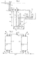
- the tangential inlets 6 serve to impart a swirl to the jet of water entering the chamber 7.
- the air is entrained by the water stream in the form of bubbles, so that when the narrow cylindrical section of the pipe 5 is reached the water is impregnated with bubbles of air.
- the air is carried to the bottom of the pipe 5 to an air/water separating chamber 9.
- the air separates from the water and passes upwardly via an air pipe 10.
- the water passes around a baffle 11 and returns upwardly through a return pipe 12.
- the pipe 12 feeds into a surge tank 13 in which is arranged a pump 14.
- the pump 14 serves to raise water into the air inclusion chamber 7 via a tangantial inlet 15 when there is an inadequate flow of water through the feed pipe 4.
- valve 51 between the pump and the chamber is closed, and a valve in the feed pipe 4 can be operated to control inlet water pressure.
- valve 50 in the pipe 4 is closed and the pump 14 is actuated to raise water to the air inclusion chamber 7.
- a suitable design velocity can, therefore, be maintained at all times in the compressor so that a correct supply of compressed air is produced.
- the pressure of water from the pump is controlled by operation of the valve 51 and this permits air at a pressure higher than atmospheric at the venturi throat.
- the drive head of the compressor is determined by the excess of the mass of the water/air mixture per unit volume in the pipe 5 over that in the pipe 12.
- This drive head must be sufficient to ensure that the velocity in the down pipe 5 is greater than the velocity at which air bubbles would rise in the water column if it were stationary.
- H d The maximum drive head possible is designated in Figure 1 by the symbol H d , which represents the elevation of the top of the pipe 5 over that of the maximum hydrostatic height of the pipe 12.
- the design and function of the air inclusion chamber 7 is of critical importance to the successful operation of the hydraulic air compressor of the invention.
- This swirling or vortical motion of the water serves to draw air into the water stream.
- the turbulent nature of the water as it enters the chamber 7 is conducive to the introduction of air.
- venturi effect created as the water passes the throat section at the bottom of the chamber 7 acts to increase air entrainment.
- the water may form into droplets with the result that entrainment is enhanced since the air can enter the stream above zero gauge pressure assisted by the venturi effect for uniform distribution throughout the body of water.
- the inertia of the issuing jet at the venturi throat enables the entrainment of air at pressure substantially above atmospheric pressure.
- Air which has already been compressed can therefore be recycled via the hydraulic air compressor for further compression from a volume equal to that of the chamber from which liquid is being displaced.
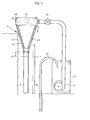
- the chamber has an upper cylindrical portion 40 and a lower frustro- concial portion 41.
- portion 41 there is a shorter member 42 of fustro-conical shape so that there is a gap between the walls of the portion 41 and the member 42.
- the air inlet 8 is in communication with this gap 43.
- a further important feature of the invention is the fact that the air can actually be cooled down while undergoing compression in the compressor.
- the compression of the air can be considered to be sub-isothermal.
- the water had an inlet temperature of 15,5 o C while ambient temperature was 21,1 C.
- the air temperature was thus some 5,6°C lower than the ambient or inlet air temperatures.
- a modification to the compressor which is not shown in the drawings involves the use of a second air/water separating chamber part-way up the return pipe 12.
- the air which separates from the water in the chamber 9 is oxygen deficient, since oxygen will have become dissolved in the water at the high pressure involved in the operation of the hydraulic air compressor of the invention.
- a second separating chamber allows for the separation of oxygen rich air at a pressure determined by the hydrostatic head existing between the water level in the second separating chamber and the upper level of the return pipe 12.
- the surplus could provide a freezer capability.
- Pressurised feed can be provided by a conventional centrifugal pump as shown in Figure 2.
- the pressurisation is provided by a pump arrangement with twin pneumatic displacement chambers as shown schematically in Figure 1.
- the capacity of the surge tank 13 as measured from the top of the pump 14 to the top of the tank should be at least 10% more than the total volume of the air pipe 10 and the excess air relief pipe between the chamber 9 and the top of the pump, or a separate relief tank could be provided.
- the hydraulic air compressor of the invention has a number of important applications:
- a conventional gas turbine drives its own adiabatic compressor stage and the air must be filtered.
- the compressor stage represents a considerable bulk and weight factor.
- the pressure available from the hydraulic air compressor of the invention may be substantially greater than those available from the conventional compressor stage.
- the compressed air from the hydraulic air compressor can be fed directly at exact pressure required by the combustion chamber of a ram jet or turbine, and can be fed to the combustion chamber, after passing through a heat exchanger, at the best temperature.
- fuel is burnt in the oxygen enriched compressed air environment to produce hot compressed gases which are then expanded adiabatically through a turbine stage.
- the resulting energy can be used for electrical generation or the operation of other devices.
- Both the inlets 23 and 24 are connected to the air pipe 10 of the hydraulic air compressor, and a two-way valve 31 can be operated to feed the compressed air either to the inlet 23 or to the inlet 24. 30
- a two-way valve 31 can be operated to feed the compressed air either to the inlet 23 or to the inlet 24.
- the compressed air in the upper part of the chamber 21 therefore pushes the water out through the outlet 25, and to a common water line 32.
- the chamber 22, having exhausted to atmospheric pressure, or recycled is being recharged with water via the line 28.
- the outlet 26 is closed, the inlet 24 is closed but the air pipe 30 is open.
- Water enters at a relatively low pressure through the pipe 28 and displaces the air in the top of the chamber 22.
- the displacement or air can be aided by the suction generated in the air inclusion chamber 7 of the compressor which can serve to suck the air out of the upper part of the chamber 22.
- the pressure of the air to the air mixing chamber 7 can be higher than atmospheric because of the inertia of the jet issuing from the venturi orifice.
- the chambers are switched over and compressed air is passed to the inlet 24 so that the chamber 22 which is now full of water, can be pumped out by the air. Whilst this is happening the chamber 21 is being refilled. One can therefore get a continuous feed of water under pressure through the line 32.
- the pump can be used to pump irrigation water using eg. the overflow from surge tank 13 or to provide any sort of pumping facility as pumping from mines, wells, boreholes, lakes or even shallow swamps, to any head.
- the compressed air could also be used to inject water into the combustion chamber of a gas turbine or ram jet as described in the preceding section of this specification, to ensure atomisation and therefore to produce greater power from the turbine, or for the injection of chemicals such as chlorine or soda-ash into water to make it potable.
- the air from the injector pump exhaust is at very low temperature.
- An advantage of the use of pneumatic displacement pump for the pressurisation of a liquid is that the air is filtered and the liquid uncontaminated with oil etc.
- the isothermally compressed air from the hydraulic air compressor can be used to supply freezer temperatures by allowing it to expand adiabatically while doing work.
- extremely low temperatures are obtainable in accordance with the conventional gas laws, ie. with an expansion ratio of 1 to 3 and ambient of plus 40°C, (104°F) by the gas expansion formula
- Gases such as A5 NH 3 can be delivered to distant points from any remo te source by condensing the gas to liquid wherever required.
Landscapes
- Engineering & Computer Science (AREA)
- Chemical & Material Sciences (AREA)
- Combustion & Propulsion (AREA)
- Mechanical Engineering (AREA)
- General Engineering & Computer Science (AREA)
- Jet Pumps And Other Pumps (AREA)
Priority Applications (1)
| Application Number | Priority Date | Filing Date | Title |
|---|---|---|---|
| EP82304298A EP0100799A1 (de) | 1982-08-13 | 1982-08-13 | Hydraulischer Luftkompressor |
Applications Claiming Priority (1)
| Application Number | Priority Date | Filing Date | Title |
|---|---|---|---|
| EP82304298A EP0100799A1 (de) | 1982-08-13 | 1982-08-13 | Hydraulischer Luftkompressor |
Publications (1)
| Publication Number | Publication Date |
|---|---|
| EP0100799A1 true EP0100799A1 (de) | 1984-02-22 |
Family
ID=8189738
Family Applications (1)
| Application Number | Title | Priority Date | Filing Date |
|---|---|---|---|
| EP82304298A Withdrawn EP0100799A1 (de) | 1982-08-13 | 1982-08-13 | Hydraulischer Luftkompressor |
Country Status (1)
| Country | Link |
|---|---|
| EP (1) | EP0100799A1 (de) |
Cited By (9)
| Publication number | Priority date | Publication date | Assignee | Title |
|---|---|---|---|---|
| EP0162814A1 (de) * | 1984-03-29 | 1985-11-27 | Vincenzo Brugnoli | Vorrichtung zur Umwandlung hydrostatischer Druckenergie zu nutzbarer Energie |
| WO1991017359A1 (en) * | 1990-04-27 | 1991-11-14 | Hydro Energy Associates Limited | Hydro-electric power conversion system |
| US5377485A (en) * | 1990-04-27 | 1995-01-03 | Hydro Energy Associates Limited | Electric power conversion system |
| EP1096142A3 (de) * | 1999-10-25 | 2004-04-07 | Daniel Savonie | Wasserkraftanlage mit Druckluftturbine |
| WO2015026891A1 (en) * | 2013-08-21 | 2015-02-26 | Paha Designs, Llc | Energy conversion system and method |
| CN106050522A (zh) * | 2016-05-26 | 2016-10-26 | 武汉大学 | 一种海水淡化中曝气发电装置 |
| CN109141058A (zh) * | 2018-09-30 | 2019-01-04 | 洛阳天泽气体有限公司 | 一种空气换热器用水冷降温装置 |
| WO2021046525A1 (en) * | 2019-09-05 | 2021-03-11 | Kenneth Hanson | Linear gas compressor |
| WO2022157616A1 (en) * | 2021-01-22 | 2022-07-28 | Fraenkel Wright Limited | Gas storage apparatus and method |
Citations (5)
| Publication number | Priority date | Publication date | Assignee | Title |
|---|---|---|---|---|
| FR1081853A (fr) * | 1953-05-07 | 1954-12-23 | Electricite De France | Procédé et dispositifs pour le réglage d'installations comprenant un compresseur hydraulique et une turbine à gaz |
| US3754147A (en) * | 1971-10-18 | 1973-08-21 | Arizona Aqualectra | Method and system for conversion of water and development of power |
| US3939356A (en) * | 1974-07-24 | 1976-02-17 | General Public Utilities Corporation | Hydro-air storage electrical generation system |
| US4110980A (en) * | 1977-10-13 | 1978-09-05 | Foulke Willing B | Apparatus for producing mechanical kinetic energy from falling water |
| GB2001395A (en) * | 1977-07-25 | 1979-01-31 | Norton J | System for generating electrical energy utilizing combined water power and combustible fuel sources |
-
1982
- 1982-08-13 EP EP82304298A patent/EP0100799A1/de not_active Withdrawn
Patent Citations (5)
| Publication number | Priority date | Publication date | Assignee | Title |
|---|---|---|---|---|
| FR1081853A (fr) * | 1953-05-07 | 1954-12-23 | Electricite De France | Procédé et dispositifs pour le réglage d'installations comprenant un compresseur hydraulique et une turbine à gaz |
| US3754147A (en) * | 1971-10-18 | 1973-08-21 | Arizona Aqualectra | Method and system for conversion of water and development of power |
| US3939356A (en) * | 1974-07-24 | 1976-02-17 | General Public Utilities Corporation | Hydro-air storage electrical generation system |
| GB2001395A (en) * | 1977-07-25 | 1979-01-31 | Norton J | System for generating electrical energy utilizing combined water power and combustible fuel sources |
| US4110980A (en) * | 1977-10-13 | 1978-09-05 | Foulke Willing B | Apparatus for producing mechanical kinetic energy from falling water |
Cited By (10)
| Publication number | Priority date | Publication date | Assignee | Title |
|---|---|---|---|---|
| EP0162814A1 (de) * | 1984-03-29 | 1985-11-27 | Vincenzo Brugnoli | Vorrichtung zur Umwandlung hydrostatischer Druckenergie zu nutzbarer Energie |
| WO1991017359A1 (en) * | 1990-04-27 | 1991-11-14 | Hydro Energy Associates Limited | Hydro-electric power conversion system |
| US5377485A (en) * | 1990-04-27 | 1995-01-03 | Hydro Energy Associates Limited | Electric power conversion system |
| EP1096142A3 (de) * | 1999-10-25 | 2004-04-07 | Daniel Savonie | Wasserkraftanlage mit Druckluftturbine |
| WO2015026891A1 (en) * | 2013-08-21 | 2015-02-26 | Paha Designs, Llc | Energy conversion system and method |
| US10001107B2 (en) | 2013-08-21 | 2018-06-19 | Paha Designs, Llc | Energy conversion system and method |
| CN106050522A (zh) * | 2016-05-26 | 2016-10-26 | 武汉大学 | 一种海水淡化中曝气发电装置 |
| CN109141058A (zh) * | 2018-09-30 | 2019-01-04 | 洛阳天泽气体有限公司 | 一种空气换热器用水冷降温装置 |
| WO2021046525A1 (en) * | 2019-09-05 | 2021-03-11 | Kenneth Hanson | Linear gas compressor |
| WO2022157616A1 (en) * | 2021-01-22 | 2022-07-28 | Fraenkel Wright Limited | Gas storage apparatus and method |
Similar Documents
| Publication | Publication Date | Title |
|---|---|---|
| US7089743B2 (en) | Method for operating a power plant by means of a CO2 process | |
| US4797563A (en) | Power plant | |
| US4673335A (en) | Gas compression with hydrokinetic amplifier | |
| EP0100799A1 (de) | Hydraulischer Luftkompressor | |
| CA1136430A (en) | System for generating electrical energy utilizing combined water power and combustible fuel sources | |
| US4110980A (en) | Apparatus for producing mechanical kinetic energy from falling water | |
| US4391552A (en) | Apparatus and method for eliminating champagne effect in compressed air energy storage systems | |
| CN102852567A (zh) | 热力过程采用喷射抽气节能方法 | |
| US6334758B1 (en) | Pump-ejector compression unit and variants | |
| RU97109381A (ru) | Способ работы жидкостно-газового эжектора | |
| RU2016268C1 (ru) | Эжекторная установка | |
| WO2024062465A1 (en) | Isothermal compressor and condenser nozzle | |
| US6276140B1 (en) | Device to generate energy through a turbo engine | |
| US4132077A (en) | Process and apparatus for obtaining useful energy from a body of liquid at moderate temperature | |
| US1537264A (en) | Method of and apparatus for elevating liquids by a multilift uniflow airlift system | |
| KR20250033136A (ko) | 증기 해머 펌프 및 전력 시설 | |
| CN114321028A (zh) | 一种气态物质处理方法 | |
| RU2142070C1 (ru) | Жидкостно-газовый эжектор | |
| RU2011022C1 (ru) | Струйная гидрокомпрессорная установка | |
| SU1721218A2 (ru) | Способ сбора нефти и газа | |
| US1777817A (en) | Vacuum pump | |
| GB2185534A (en) | A fluid displacement or compression method | |
| CN1097150C (zh) | 用涡轮机获得能量的装置 | |
| RU2184280C1 (ru) | Способ сжатия газа и устройство для его осуществления | |
| SU1474334A1 (ru) | Газлифтна установка |
Legal Events
| Date | Code | Title | Description |
|---|---|---|---|
| PUAI | Public reference made under article 153(3) epc to a published international application that has entered the european phase |
Free format text: ORIGINAL CODE: 0009012 |
|
| AK | Designated contracting states |
Designated state(s): AT BE CH DE FR GB IT LI LU NL SE |
|
| STAA | Information on the status of an ep patent application or granted ep patent |
Free format text: STATUS: THE APPLICATION IS DEEMED TO BE WITHDRAWN |
|
| 18D | Application deemed to be withdrawn |
Effective date: 19841023 |