EP0100860A1 - Appareil de balayage par ultrasons - Google Patents
Appareil de balayage par ultrasons Download PDFInfo
- Publication number
- EP0100860A1 EP0100860A1 EP83106515A EP83106515A EP0100860A1 EP 0100860 A1 EP0100860 A1 EP 0100860A1 EP 83106515 A EP83106515 A EP 83106515A EP 83106515 A EP83106515 A EP 83106515A EP 0100860 A1 EP0100860 A1 EP 0100860A1
- Authority
- EP
- European Patent Office
- Prior art keywords
- ultrasound
- ultrasonic
- transducer
- heads
- drive
- Prior art date
- Legal status (The legal status is an assumption and is not a legal conclusion. Google has not performed a legal analysis and makes no representation as to the accuracy of the status listed.)
- Granted
Links
- 238000002604 ultrasonography Methods 0.000 claims abstract description 49
- 230000005540 biological transmission Effects 0.000 claims abstract description 6
- 230000005855 radiation Effects 0.000 claims abstract description 4
- 239000003990 capacitor Substances 0.000 claims description 3
- 239000007788 liquid Substances 0.000 claims description 3
- 238000004804 winding Methods 0.000 claims description 3
- 230000005672 electromagnetic field Effects 0.000 claims 1
- 230000003601 intercostal effect Effects 0.000 description 3
- 239000002184 metal Substances 0.000 description 3
- 239000004033 plastic Substances 0.000 description 3
- 229920003023 plastic Polymers 0.000 description 3
- 238000013461 design Methods 0.000 description 2
- 238000011161 development Methods 0.000 description 2
- 239000012528 membrane Substances 0.000 description 2
- -1 polyethylene Polymers 0.000 description 2
- 239000004698 Polyethylene Substances 0.000 description 1
- 239000004743 Polypropylene Substances 0.000 description 1
- 210000003109 clavicle Anatomy 0.000 description 1
- 238000010276 construction Methods 0.000 description 1
- 230000008878 coupling Effects 0.000 description 1
- 238000010168 coupling process Methods 0.000 description 1
- 238000005859 coupling reaction Methods 0.000 description 1
- 238000013016 damping Methods 0.000 description 1
- 238000009429 electrical wiring Methods 0.000 description 1
- 230000005520 electrodynamics Effects 0.000 description 1
- 230000002349 favourable effect Effects 0.000 description 1
- 238000000034 method Methods 0.000 description 1
- 229920000573 polyethylene Polymers 0.000 description 1
- 229920001155 polypropylene Polymers 0.000 description 1
- 238000012545 processing Methods 0.000 description 1
- 230000000717 retained effect Effects 0.000 description 1
- 238000012549 training Methods 0.000 description 1
- XLYOFNOQVPJJNP-UHFFFAOYSA-N water Substances O XLYOFNOQVPJJNP-UHFFFAOYSA-N 0.000 description 1
Images
Classifications
-
- G—PHYSICS
- G10—MUSICAL INSTRUMENTS; ACOUSTICS
- G10K—SOUND-PRODUCING DEVICES; METHODS OR DEVICES FOR PROTECTING AGAINST, OR FOR DAMPING, NOISE OR OTHER ACOUSTIC WAVES IN GENERAL; ACOUSTICS NOT OTHERWISE PROVIDED FOR
- G10K11/00—Methods or devices for transmitting, conducting or directing sound in general; Methods or devices for protecting against, or for damping, noise or other acoustic waves in general
- G10K11/18—Methods or devices for transmitting, conducting or directing sound
- G10K11/26—Sound-focusing or directing, e.g. scanning
- G10K11/35—Sound-focusing or directing, e.g. scanning using mechanical steering of transducers or their beams
- G10K11/352—Sound-focusing or directing, e.g. scanning using mechanical steering of transducers or their beams by moving the transducer
- G10K11/355—Arcuate movement
Definitions
- the invention relates to an ultrasound device for sector scanning, with an applicator housing for an ultrasound transmission / reception system and associated drive and control means, wherein the ultrasound transmission / reception system consists of a pivotable ultrasound head with at least one transducer element, which is around a swivel axis can be swiveled periodically within a predeterminable angular range.
- the sector scan method is used in particular for cardiological examinations, since there is an acoustic window between the ribs on the one hand intercostal) and above the clavicle on the other hand (suprasternal), through which ultrasound can be irradiated.
- Sector scanners are known in a variety with different technical training. The technical development is aimed at developing applicators that are as small and easy to handle as possible.
- a sector scan can be generated mechanically or electronically.
- an ultrasound head with a reception / transducer system is periodically pivoted back and forth, while in the second case an electronic beam deflection based on the principle of the "phased array" delivers the corresponding scan area.
- the drive for tilting the ultrasound head can take place, for example, via an eccentric with an associated push crank.
- the transducer can also be used as a rotary roller are designed with a plurality of individual oscillators attached to the circumference, which individual oscillators are cyclically switched on and off successively when the roller rotates.
- the object of the invention is therefore to provide an ultrasound device for sector scanning, which is application-friendly and offers the user advantages in handling compared to the previously known sector scanners.
- the object is achieved in that two in applications by means of a single drive position opposing ultrasound heads, the transducer elements of which differ from one another, can be driven in such a way that during a scanning movement with ultrasound radiation from the one transducer, the other transducer executes an opposite pivoting movement for the purpose of compensating mechanical forces.
- the ultrasound device thus advantageously on the one hand compensates for the inertia forces which inevitably occur in mechanically driven sector scanners; on the other hand, the ultrasound device simultaneously has two ultrasound heads with different working frequencies, which can be easily brought into the application position if required.
- an examiner can guide the applicator with a guide part in the manner of a pen and thus position it precisely.
- the ultrasound head to be applied can be moved in all directions and can be applied well in cardiological examinations.
- the new spatial shape of the applicator housing with the guide part allows for excellent handling when swiveling the guide part when applied in the intercostal or also in the suprasternal space. The latter is only possible with difficulty with the devices of the prior art.
- the design of the movement system in two forms is preferably implemented by an electromagnetic drive.
- an electromagnetic drive By using a double armature, corresponding windings and magnetic elements on the ultrasonic heads, complicated mechanics can be avoided and the applicator can be kept small.
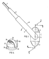
- 1 denotes the applicator housing. This is approximately cylindrical in shape and has caps 2 and 3 on the top and bottom as approximately symmetrical spherical cap parts.
- the dome parts consist of flexible, but inherently stable plastic, for example made of polyethylene or polypropylene. They each complete a scanner with the associated liquid flow path.
- the applicator housing 1 with the two scanner caps 2 and 3 is extremely compact. This allows the applicator to be applied, for example, between the ribs of a patient. Sector scans for sectional representations of the heart can thus be generated in particular.
- the applicator housing 1 is enclosed in the middle on both sides by a guide part 4.
- a connector for the applicator housing 2 with an axis of rotation 5 is attached to the guide part 4 proximally.
- the housing part 1 is essentially made of plastic and accommodates an electromagnetic drive with a yoke, coil and rotating armature.
- the housing 1 is rotatably or tiltably supported on both sides in the guide housing 4 by means of a bearing device, so that the applicator housing 1 can optionally be brought into the suitable application position using one of the scanners.
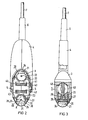
- 20 and 30 mean two ultrasound heads, which are each mounted in housing 1 so as to be pivotable about a predeterminable angular range about axes of rotation A and B, respectively.
- the ultrasonic transducers 21 and 31 are attached to the ultrasound head 20 and 30 on the application side in each case via damping bodies (not shown).
- Rotary armatures 22 and 32 are formed by the ultrasound heads 20 and 30, respectively, which have permanent magnet layers 23 and 33 on the back. Permanent magnets of this type are formed, for example, on the basis of rare earths and can be applied in layers to the armature parts 22 and 32. They are magnetized according to the respective requirement, for example in a circumferential sequence of approximately 90 ° with a north pole, a south pole and again a north pole.
- the ultrasound heads 20 and 30 are closed off by the caps 2 and 3 already mentioned.
- an electromagnet is attached between the two pivotably held ultrasound heads 20 and 30, with which the movement of both ultrasound heads can be activated at the same time.
- the electromagnet consists of stacked transformer sheets 40, which are punched out in such a way that they each pole pieces forming end 'for the rear side formed by the ultrasonic transducers anchor surfaces.
- a yoke is formed with recesses 41 and 42 through which the windings of a coil 43 run.
- the required, dynamically changeable magnetic field can be generated with the described electromagnet.
- the armature is consequently moved in such a way that a pivoting movement is carried out when the field changes.
- One of the two transducers 21 and 31 can be activated simultaneously for ultrasound radiation or reception.
- the electrical wiring and signal processing units are not shown in the present figures. However, it can be seen that there is sufficient space in the guide part 4 for accommodating such units. This means that the actual applicator housing 1 can be kept extremely compact to the desired extent.
- the structural design of the electromagnet with yoke 40 and coil 41 can also be seen. It becomes particularly clear here the construction of the ultrasound head 20 as an armature with a permanent magnet: a web 27 is attached to the axis of rotation 26. The permanent magnet layer 23 is located on this.
- the armature part 22 is adapted to the shape of the pole shoes of the yoke 40 and is located in a shaft-like cutout of the actual plastic housing.
- the anchor part also has a metal tab 28 on the side.
- a corresponding metal flag 29 is still located on the in-wall housing shaft.
- a rotary capacitor is thus formed, so to speak, which can be used to detect the position of the rotary armature and thus also for control purposes.
- the second ultrasound head 30 is also constructed with respect to the armature and the capacitive measuring element.
- the function of the pivotable ultrasound head with a capacitive measuring element becomes clearer from the perspective illustration in FIG.
- the reference symbols for the transducer element pivot axis and the permanent magnet layer have already been explained above.
- the two metal lugs 28 and 29 face each other, so that a capacitor is formed.
- the effective area is changed, with which every position of the transducer can be detected.
- an electromagnetic drive is particularly suitable for a compact device structure in the sense of the invention.
- an applicator housing with two ultrasound heads located distally opposite one another can also be designed with a mechanical drive.
- the favorable properties with regard to application and handling can be retained.
- an ent speaking applicator with mechanical drive thus falls under the invention.
Landscapes
- Physics & Mathematics (AREA)
- Engineering & Computer Science (AREA)
- Acoustics & Sound (AREA)
- Multimedia (AREA)
- Ultra Sonic Daignosis Equipment (AREA)
- Measurement Of Velocity Or Position Using Acoustic Or Ultrasonic Waves (AREA)
Applications Claiming Priority (2)
| Application Number | Priority Date | Filing Date | Title |
|---|---|---|---|
| DE3226916 | 1982-07-19 | ||
| DE19823226916 DE3226916A1 (de) | 1982-07-19 | 1982-07-19 | Ultraschall-geraet fuer sektorabtastung |
Publications (2)
| Publication Number | Publication Date |
|---|---|
| EP0100860A1 true EP0100860A1 (fr) | 1984-02-22 |
| EP0100860B1 EP0100860B1 (fr) | 1986-05-07 |
Family
ID=6168742
Family Applications (1)
| Application Number | Title | Priority Date | Filing Date |
|---|---|---|---|
| EP83106515A Expired EP0100860B1 (fr) | 1982-07-19 | 1983-07-04 | Appareil de balayage par ultrasons |
Country Status (4)
| Country | Link |
|---|---|
| US (1) | US4530362A (fr) |
| EP (1) | EP0100860B1 (fr) |
| JP (1) | JPS5928952A (fr) |
| DE (2) | DE3226916A1 (fr) |
Families Citing this family (18)
| Publication number | Priority date | Publication date | Assignee | Title |
|---|---|---|---|---|
| JPH0355235Y2 (fr) * | 1985-02-18 | 1991-12-09 | ||
| US4869257A (en) * | 1985-06-03 | 1989-09-26 | Picker International, Inc. | Ultrasonic mechanical sector scanning transducer probe assembly |
| US4773426A (en) * | 1985-06-03 | 1988-09-27 | Picker International, Inc. | Ultrasonic mechanical sector scanning transducer probe assembly |
| EP0219988B1 (fr) * | 1985-09-27 | 1993-10-20 | Mentor O & O Inc. | Instrument manuel autonome à ultrason pour usage ophtalmologique |
| JP2618920B2 (ja) * | 1987-09-18 | 1997-06-11 | オリンパス光学工業株式会社 | 超音波内視鏡 |
| US4868476A (en) * | 1987-10-30 | 1989-09-19 | Hewlett-Packard Company | Transducer with integral memory |
| US5070734A (en) * | 1988-06-15 | 1991-12-10 | Matsushita Electric Industrial Co., Ltd. | Ultrasonic diagnostic apparatus |
| US5315512A (en) * | 1989-09-01 | 1994-05-24 | Montefiore Medical Center | Apparatus and method for generating image representations of a body utilizing an ultrasonic imaging subsystem and a three-dimensional digitizer subsystem |
| US5100318A (en) * | 1990-04-13 | 1992-03-31 | Periosonics, Inc. | Ultrasonic method and apparatus for measuring the periodontal pocket |
| US5465724A (en) * | 1993-05-28 | 1995-11-14 | Acuson Corporation | Compact rotationally steerable ultrasound transducer |
| US5558623A (en) * | 1995-03-29 | 1996-09-24 | Rich-Mar Corporation | Therapeutic ultrasonic device |
| USD403421S (en) | 1995-03-29 | 1998-12-29 | Rich-Mar Corporation | Ultrasonic applicator |
| GB9620229D0 (en) * | 1996-09-27 | 1996-11-13 | Graphers Systems Ltd | Apparatus for measuring the quality of spot welds |
| US6698279B1 (en) | 1996-10-23 | 2004-03-02 | Ultrasonics And Magnetics Corporation | Method and apparatus for testing the integrity of railroad locomotive wheels and railroad car wheels |
| US6546803B1 (en) | 1999-12-23 | 2003-04-15 | Daimlerchrysler Corporation | Ultrasonic array transducer |
| US7132617B2 (en) * | 2002-02-20 | 2006-11-07 | Daimlerchrysler Corporation | Method and system for assessing quality of spot welds |
| JP2005533456A (ja) * | 2002-07-18 | 2005-11-04 | メジャメント スペシャリティーズ インク | 電子機器用の超音波トランスデューサ |
| US10945706B2 (en) | 2017-05-05 | 2021-03-16 | Biim Ultrasound As | Hand held ultrasound probe |
Citations (4)
| Publication number | Priority date | Publication date | Assignee | Title |
|---|---|---|---|---|
| GB2027197A (en) * | 1978-07-18 | 1980-02-13 | Diasonics Inc | Ultrasonic imaging apparatus |
| DE2941865A1 (de) * | 1979-10-16 | 1981-05-14 | Siemens AG, 1000 Berlin und 8000 München | Ultraschallgeraet fuer sektorabtastung |
| DE2945586A1 (de) * | 1979-11-12 | 1981-05-21 | Kraftwerk Union AG, 4330 Mülheim | Mehrfachhalterung fuer pruefkoepfe, insbesondere ultraschall-pruefkoepfe |
| EP0051927A1 (fr) * | 1980-10-16 | 1982-05-19 | Dymax Corporation | Transducteur ultrasonore |
Family Cites Families (9)
| Publication number | Priority date | Publication date | Assignee | Title |
|---|---|---|---|---|
| US4030347A (en) * | 1975-10-31 | 1977-06-21 | Electrical Power Research Institute | Biaxial capacitance strain transducer |
| US4264162A (en) * | 1978-06-21 | 1981-04-28 | Canon Kabushiki Kaisha | Drive system for electromagnetically driven shutter |
| AT358714B (de) * | 1979-01-25 | 1980-09-25 | Kretztechnik Gmbh | Ultraschallgeraet zur durchfuehrung von unter- suchungen nach dem schnittbildverfahren |
| US4241324A (en) * | 1979-09-28 | 1980-12-23 | Mcgraw-Edison Company | Magnetic core for electrical transformers |
| JPS5672423A (en) * | 1979-11-16 | 1981-06-16 | Canon Inc | Electromagnetic-drive slit exposure shutter |
| JPS56152635A (en) * | 1980-04-28 | 1981-11-26 | Olympus Optical Co | Ultrasonic diagnosis apparatus |
| US4315435A (en) * | 1980-06-30 | 1982-02-16 | Second Foundation | Dual scan ultrasonic scanner |
| JPS5771113A (en) * | 1980-10-22 | 1982-05-01 | Hitachi Ltd | Three phase three leg core |
| US4433691A (en) * | 1981-10-05 | 1984-02-28 | Honeywell Inc. | Moving torque coil oscillatory drive member |
-
1982
- 1982-07-19 DE DE19823226916 patent/DE3226916A1/de not_active Withdrawn
-
1983
- 1983-07-04 DE DE8383106515T patent/DE3363381D1/de not_active Expired
- 1983-07-04 EP EP83106515A patent/EP0100860B1/fr not_active Expired
- 1983-07-11 US US06/512,251 patent/US4530362A/en not_active Expired - Fee Related
- 1983-07-13 JP JP58127535A patent/JPS5928952A/ja active Pending
Patent Citations (4)
| Publication number | Priority date | Publication date | Assignee | Title |
|---|---|---|---|---|
| GB2027197A (en) * | 1978-07-18 | 1980-02-13 | Diasonics Inc | Ultrasonic imaging apparatus |
| DE2941865A1 (de) * | 1979-10-16 | 1981-05-14 | Siemens AG, 1000 Berlin und 8000 München | Ultraschallgeraet fuer sektorabtastung |
| DE2945586A1 (de) * | 1979-11-12 | 1981-05-21 | Kraftwerk Union AG, 4330 Mülheim | Mehrfachhalterung fuer pruefkoepfe, insbesondere ultraschall-pruefkoepfe |
| EP0051927A1 (fr) * | 1980-10-16 | 1982-05-19 | Dymax Corporation | Transducteur ultrasonore |
Also Published As
| Publication number | Publication date |
|---|---|
| JPS5928952A (ja) | 1984-02-15 |
| EP0100860B1 (fr) | 1986-05-07 |
| DE3363381D1 (en) | 1986-06-12 |
| DE3226916A1 (de) | 1984-01-19 |
| US4530362A (en) | 1985-07-23 |
Similar Documents
| Publication | Publication Date | Title |
|---|---|---|
| EP0100860B1 (fr) | Appareil de balayage par ultrasons | |
| DE2660208C3 (de) | Ultraschall-Bildgerät zur Erzeugung von Querschnittsbildern | |
| DE68907694T2 (de) | Vorrichtung zum Fokussieren eines Ultraschallbündels in drei Dimensionen. | |
| DE4209394C2 (de) | Ultraschallabbildungsgerät | |
| DE3783281T2 (de) | Ultraschallsonde. | |
| DE69721728T2 (de) | Ultraschallsende-/empfangsgerät | |
| DE3100717C2 (de) | Ultraschallschnittbildgerät | |
| DE3884346T3 (de) | Stosswellenbehandlungseinrichtung. | |
| DE3147482C1 (de) | Ultraschallpruefkopf mit einer Vielzahl von Ultraschallwandlern | |
| DE3226976A1 (de) | Ultraschallapparat fuer medizinische untersuchungen | |
| EP0166976B1 (fr) | Ensemble de transducteurs à ultrasons | |
| DE2928560A1 (de) | Bildgewinnungsvorrichtung fuer ein ultraschall-abbildungssystem | |
| EP0355177A1 (fr) | Appareil pour la destruction à distance dans le corps d'un être vivant | |
| DE10217342A1 (de) | Verfahren und Einrichtung zur Erzeugung medizinischer Ultraschallbilder | |
| DE2529112A1 (de) | Ultraschall-applikator fuer die ultraschallabtastung von koerpern | |
| DE2619231A1 (de) | Verfahren und vorrichtung zur ultraschallpruefung | |
| DE3307384A1 (de) | Ultraschallapparat fuer medizinische untersuchungen | |
| DE68920639T2 (de) | Ultraschalldiagnosegerät. | |
| DE3624668C2 (fr) | ||
| DE3121993C2 (de) | Ultraschall-Abtastgerät | |
| EP0097917B1 (fr) | Appareil de tomographie par ultrasons | |
| DE2738773C2 (de) | Elektroakustischer Wandler, insbesondere für eine Armbanduhr oder eine Taschenuhr | |
| DE3029449A1 (de) | Ultraschall-abtastgeraet | |
| DE3214887C2 (fr) | ||
| DE2709570C2 (de) | Ultraschallimpulsechogerät zur hochaufgelösten bildmäßigen Darstellung |
Legal Events
| Date | Code | Title | Description |
|---|---|---|---|
| PUAI | Public reference made under article 153(3) epc to a published international application that has entered the european phase |
Free format text: ORIGINAL CODE: 0009012 |
|
| AK | Designated contracting states |
Designated state(s): DE FR GB |
|
| 17P | Request for examination filed |
Effective date: 19840329 |
|
| GRAA | (expected) grant |
Free format text: ORIGINAL CODE: 0009210 |
|
| AK | Designated contracting states |
Kind code of ref document: B1 Designated state(s): DE FR GB |
|
| PG25 | Lapsed in a contracting state [announced via postgrant information from national office to epo] |
Ref country code: FR Free format text: THE PATENT HAS BEEN ANNULLED BY A DECISION OF A NATIONAL AUTHORITY Effective date: 19860507 |
|
| REF | Corresponds to: |
Ref document number: 3363381 Country of ref document: DE Date of ref document: 19860612 |
|
| EN | Fr: translation not filed | ||
| PLBE | No opposition filed within time limit |
Free format text: ORIGINAL CODE: 0009261 |
|
| STAA | Information on the status of an ep patent application or granted ep patent |
Free format text: STATUS: NO OPPOSITION FILED WITHIN TIME LIMIT |
|
| 26N | No opposition filed | ||
| PG25 | Lapsed in a contracting state [announced via postgrant information from national office to epo] |
Ref country code: DE Effective date: 19880401 |
|
| GBPC | Gb: european patent ceased through non-payment of renewal fee | ||
| PG25 | Lapsed in a contracting state [announced via postgrant information from national office to epo] |
Ref country code: GB Free format text: LAPSE BECAUSE OF NON-PAYMENT OF DUE FEES Effective date: 19881122 |