EP0100868A1 - Appareil pour la fabrication de préformes tubulaires en matière synthétique - Google Patents
Appareil pour la fabrication de préformes tubulaires en matière synthétique Download PDFInfo
- Publication number
- EP0100868A1 EP0100868A1 EP83106595A EP83106595A EP0100868A1 EP 0100868 A1 EP0100868 A1 EP 0100868A1 EP 83106595 A EP83106595 A EP 83106595A EP 83106595 A EP83106595 A EP 83106595A EP 0100868 A1 EP0100868 A1 EP 0100868A1
- Authority
- EP
- European Patent Office
- Prior art keywords
- plastic
- chamber
- mandrel
- screw
- plastic chamber
- Prior art date
- Legal status (The legal status is an assumption and is not a legal conclusion. Google has not performed a legal analysis and makes no representation as to the accuracy of the status listed.)
- Granted
Links
- 238000004519 manufacturing process Methods 0.000 title claims abstract 3
- 229920003002 synthetic resin Polymers 0.000 title 1
- 239000000057 synthetic resin Substances 0.000 title 1
- 239000004033 plastic Substances 0.000 claims abstract description 70
- 229920003023 plastic Polymers 0.000 claims abstract description 70
- 238000000034 method Methods 0.000 claims description 18
- 238000006073 displacement reaction Methods 0.000 claims description 3
- 230000015572 biosynthetic process Effects 0.000 claims 2
- 238000011038 discontinuous diafiltration by volume reduction Methods 0.000 claims 1
- 230000007704 transition Effects 0.000 claims 1
- 238000000071 blow moulding Methods 0.000 abstract description 5
- 238000007654 immersion Methods 0.000 abstract description 3
- 238000007664 blowing Methods 0.000 description 5
- 238000001125 extrusion Methods 0.000 description 3
- RZVAJINKPMORJF-UHFFFAOYSA-N Acetaminophen Chemical compound CC(=O)NC1=CC=C(O)C=C1 RZVAJINKPMORJF-UHFFFAOYSA-N 0.000 description 1
- 238000001816 cooling Methods 0.000 description 1
- 230000006735 deficit Effects 0.000 description 1
- 239000003000 extruded plastic Substances 0.000 description 1
- 230000002349 favourable effect Effects 0.000 description 1
- 238000010438 heat treatment Methods 0.000 description 1
- 230000001771 impaired effect Effects 0.000 description 1
- 238000002347 injection Methods 0.000 description 1
- 239000007924 injection Substances 0.000 description 1
- 238000009434 installation Methods 0.000 description 1
- 239000000463 material Substances 0.000 description 1
- 238000011089 mechanical engineering Methods 0.000 description 1
- 230000005855 radiation Effects 0.000 description 1
- 238000000926 separation method Methods 0.000 description 1
- 238000005496 tempering Methods 0.000 description 1
- 239000012815 thermoplastic material Substances 0.000 description 1
Images

Classifications
-
- B—PERFORMING OPERATIONS; TRANSPORTING
- B29—WORKING OF PLASTICS; WORKING OF SUBSTANCES IN A PLASTIC STATE IN GENERAL
- B29C—SHAPING OR JOINING OF PLASTICS; SHAPING OF MATERIAL IN A PLASTIC STATE, NOT OTHERWISE PROVIDED FOR; AFTER-TREATMENT OF THE SHAPED PRODUCTS, e.g. REPAIRING
- B29C49/00—Blow-moulding, i.e. blowing a preform or parison to a desired shape within a mould; Apparatus therefor
- B29C49/02—Combined blow-moulding and manufacture of the preform or the parison
-
- B—PERFORMING OPERATIONS; TRANSPORTING
- B29—WORKING OF PLASTICS; WORKING OF SUBSTANCES IN A PLASTIC STATE IN GENERAL
- B29C—SHAPING OR JOINING OF PLASTICS; SHAPING OF MATERIAL IN A PLASTIC STATE, NOT OTHERWISE PROVIDED FOR; AFTER-TREATMENT OF THE SHAPED PRODUCTS, e.g. REPAIRING
- B29C48/00—Extrusion moulding, i.e. expressing the moulding material through a die or nozzle which imparts the desired form; Apparatus therefor
- B29C48/03—Extrusion moulding, i.e. expressing the moulding material through a die or nozzle which imparts the desired form; Apparatus therefor characterised by the shape of the extruded material at extrusion
- B29C48/09—Articles with cross-sections having partially or fully enclosed cavities, e.g. pipes or channels
-
- B—PERFORMING OPERATIONS; TRANSPORTING
- B29—WORKING OF PLASTICS; WORKING OF SUBSTANCES IN A PLASTIC STATE IN GENERAL
- B29C—SHAPING OR JOINING OF PLASTICS; SHAPING OF MATERIAL IN A PLASTIC STATE, NOT OTHERWISE PROVIDED FOR; AFTER-TREATMENT OF THE SHAPED PRODUCTS, e.g. REPAIRING
- B29C48/00—Extrusion moulding, i.e. expressing the moulding material through a die or nozzle which imparts the desired form; Apparatus therefor
- B29C48/25—Component parts, details or accessories; Auxiliary operations
- B29C48/36—Means for plasticising or homogenising the moulding material or forcing it through the nozzle or die
- B29C48/375—Plasticisers, homogenisers or feeders comprising two or more stages
- B29C48/388—Plasticisers, homogenisers or feeders comprising two or more stages using a screw extruder and a ram or piston
Definitions
- the present invention relates to methods and devices for producing tubular preforms from thermoplastic materials, which work according to the so-called immersion blow molding method, which is described in DE-PS 1 800 263.
- the known immersion blow molding process is carried out in such a way that the preform is formed by inserting the blow mandrel by means of a known relative movement between it and an outlet nozzle into a chamber filled with plastic and then re-guiding the mandrel out with the plastic surrounding it.
- the object of the invention is to improve the flow conditions and at the same time to shorten the dwell time of the plastic in the chamber.
- the invention also relates to devices for carrying out the method according to the invention. These preferred embodiments of the invention have been characterized in claims 5 to 17 in detail.
- the plastic chamber also has the form of a compressible and expandable bag, which carries out the geometrical changes in shape of the plastic chamber by applying an external pressure medium or by generating negative pressure in the expansion phase.
- the advantage of the present invention is that the change in shape of the plastic chamber allows a particularly precise control of the amount of extruded plastic of the tubular preform.
- a particularly advantageous embodiment is obtained if the expandable and contractible plastic chamber is practically formed from only two bushes, namely a front and a rear bush, and if the rear bush, that is to say the nozzle facing away from the nozzle, is firmly connected to the screw chamber. Not only does this result in a particularly advantageous situation with regard to the flow conditions, but at the same time only a single sliding fit is required with relatively small sliding surfaces.
- a preferred embodiment of the invention provides that the plastic chamber with an exchangeable outlet nozzle at its front end is guided on spars outside the area of influence of the processing heat of the plastic and with its rear end is displaceable on the feed pipe for the plastic which is firmly connected to the screw chamber, whereby by the central feed of the plastic into the plastic chamber the favorable flow conditions can be improved.
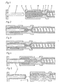
- the plastic chamber is designated by the reference number 1.
- the plastic chamber 1 is formed in its geometric shape by the front sleeve 2, which has a nozzle 3 at the outlet end of the chamber, and a rear sleeve 4, which is firmly connected to the screw chamber 5.
- the screw chamber 5, in which the screw 6 is located, is via a channel? connected to the plastic chamber 1.
- the mandrel 8 is fixed in the embodiment according to FIGS. 1 to 5. It is attached to a mouth tool 9, which is used to form a thread or the like.
- the chamber 1 is filled with plastic and thus assumes a standby position.
- the front sleeve 2 and the rear sleeve 4 moved in the same direction, but with different strokes. So that the volume of the chamber 1 was increased and the mandrel 8 immersed in the plastic without plastic escaping from the nozzle 3 before it rests on the mouth tool 9.
- the rear sleeve 4 has performed a certain stroke in the direction of the mandrel 8, whereby the chamber 1 has become smaller and the plastic completely fills the muzzle tool 9.
- This injection can also be carried out by extrusion, or also by a combination of extrusion and a corresponding stroke of the rear sleeve 4.
- the rear sleeve 4 performs a small stroke back in order to relieve the pressure previously applied to the plastic in chamber 1 Stroke also serves to equalize the volume in the chamber 1 in the case of (continuous) extrusion which continues from the screw chamber 5.
- front sleeve 2 and rear sleeve 4 have moved back simultaneously, but with different strokes.
- the movements of both elements are coordinated with one another and according to an adjustable program, so that the preform 11 is formed on the mandrel 8 in a precisely determined wall thickness.
- the front sleeve 2 has passed the mandrel 8 along its length, and the preform 11 is separated from the full strand connecting it to the nozzle 3.
- the separation can be carried out by the knife 12 or by further simultaneous retraction of the front sleeve 2 and the rear sleeve 4, which causes the plastic strand to constrict and tear off.
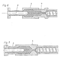
- FIGS. 1 to 5 shows two variants of the working methods described in FIGS. 1 to 5.
- One is a device in which the rear sleeve 4 is moved in a stationary manner and in connection with the movable mandrel 8 the front sleeve 2 is moved.
- the further variant is a device in which the front sleeve 2 is stationary and the rear sleeve 4 is moved in connection with the movable mandrel 8. Otherwise, both working methods are analogous to the phases described in FIGS. 1 to 5.
- Fig. 7 shows an embodiment in which the front sleeve 2 is not above but in the rear sleeve 4.
- bushes 2 and 4 are simple turned parts and can be easily replaced.
- the front sleeve 2 as well as the rear sleeve 4 can also be designed very differently according to the geometric requirements, e.g. for certain diameter ratios and strokes, as well as being influenced by the type of plastic and the dimensions of the preforms to be produced.
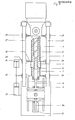
- the extruder 16 has a cylinder 17 and a screw 6, the free space of which forms a chamber 5 in which plastic is received via the funnel 18 in order to be plasticized and conveyed in the chamber 5, for which purpose the motor 19 the screw 6 turns.
- the volume of the chambers 1 and 1 ' can be varied by relative movement of the front sleeve 2 or 2' and the rear sleeves 4 and 4 ', which together form the sliding seats 10 and 10'.
- the chambers 1 and 1 1 have constrictions that lead directly to the screw chamber 5 as branch channels 22 and 22 1 and channel 7. It is ensured in the illustrated machine that the plastic can enter the chambers centrally and freely in all plastic chambers.
- the mode of operation is schematically explained in FIGS. 1 to 5 which represent the method steps.
- a machine can be equipped for one or more cavities.
- a double arrangement is shown here.
- the blowing tool 25 accordingly has two cavities, and in these the preforms can be expanded into hollow bodies by introducing air through the blowing mandrels.
- the blowing tool 25 is opened to remove the mold after the finished hollow body has cooled.
- the finished hollow bodies can be removed after opening the blow mold in the blowing position or while the mandrels are swinging back.
- the The mandrel carrier has three or four sets of mandrels, the further positions of removal, tempering of the preforms or the intermediate hollow bodies and stretching being available.
- the machine arrangement is preferably horizontal according to FIG. 8, the mandrels moving in a vertical plane. This means that all elements executing the process are equidistant from the operator side. With smaller machines, space-saving installation in the vertical main axis is possible, while with large machines, an arrangement angled after the extruder is advisable.
- FIG. 9 shows a variant in which the displaceable elements have a common guide.
- the sleeves 2 and 4 which are displaceable relative to one another, have guide elements 26, 26 'and 28, 28' which lie outside the thermal influence range.
- a coaxial guide is of particular importance. This object is achieved in that the associated guide elements 26, 26 ', 28, 28' and 29, 29 'move coaxially on common guides 27, 27'.
- the spars 27 and 27'o shown in FIG. 9, which are arranged in parallel, are particularly suitable for such a common guidance.
Landscapes
- Engineering & Computer Science (AREA)
- Mechanical Engineering (AREA)
- Manufacturing & Machinery (AREA)
- Blow-Moulding Or Thermoforming Of Plastics Or The Like (AREA)
- Processing And Handling Of Plastics And Other Materials For Molding In General (AREA)
Applications Claiming Priority (2)
| Application Number | Priority Date | Filing Date | Title |
|---|---|---|---|
| DE3225567 | 1982-07-07 | ||
| DE3225567 | 1982-07-08 |
Publications (2)
| Publication Number | Publication Date |
|---|---|
| EP0100868A1 true EP0100868A1 (fr) | 1984-02-22 |
| EP0100868B1 EP0100868B1 (fr) | 1986-04-02 |
Family
ID=6167956
Family Applications (1)
| Application Number | Title | Priority Date | Filing Date |
|---|---|---|---|
| EP83106595A Expired EP0100868B1 (fr) | 1982-07-08 | 1983-07-06 | Appareil pour la fabrication de préformes tubulaires en matière synthétique |
Country Status (3)
| Country | Link |
|---|---|
| US (2) | US4594212A (fr) |
| EP (1) | EP0100868B1 (fr) |
| DE (1) | DE3362779D1 (fr) |
Families Citing this family (4)
| Publication number | Priority date | Publication date | Assignee | Title |
|---|---|---|---|---|
| WO1992011989A1 (fr) * | 1991-01-03 | 1992-07-23 | David Rudy Brent | Appareil et procede de moulage par injection |
| CA2191715A1 (fr) * | 1994-05-31 | 1995-12-07 | Kim Patchett | Materiau resistant aux perforations |
| GB2303575B (en) * | 1994-05-31 | 1998-01-14 | Kim Patchet | Puncture resistant material |
| US6889763B1 (en) | 2000-10-23 | 2005-05-10 | Advanced Micro Devices, Inc. | System for rapidly and uniformly cooling resist |
Citations (2)
| Publication number | Priority date | Publication date | Assignee | Title |
|---|---|---|---|---|
| DE1800263A1 (de) * | 1968-10-01 | 1970-05-21 | Johannes Mehnert | Verfahren und Vorrichtung zum Herstellen von Hohlkoerpern aus thermoplastischen Kunststoffen |
| AT335725B (de) * | 1971-07-01 | 1977-03-25 | Schloemann Siemag Ag | Verfahren und vorrichtung zum herstellen von hohkorpern aus thermoplastischem kunststoff |
Family Cites Families (1)
| Publication number | Priority date | Publication date | Assignee | Title |
|---|---|---|---|---|
| US3751207A (en) * | 1972-03-10 | 1973-08-07 | Siemag Siegener Masch Bau | Apparatus for blow molding |
-
1983
- 1983-07-06 DE DE8383106595T patent/DE3362779D1/de not_active Expired
- 1983-07-06 EP EP83106595A patent/EP0100868B1/fr not_active Expired
- 1983-07-06 US US06/511,514 patent/US4594212A/en not_active Expired - Fee Related
-
1985
- 1985-11-27 US US06/802,852 patent/US4652229A/en not_active Expired - Fee Related
Patent Citations (2)
| Publication number | Priority date | Publication date | Assignee | Title |
|---|---|---|---|---|
| DE1800263A1 (de) * | 1968-10-01 | 1970-05-21 | Johannes Mehnert | Verfahren und Vorrichtung zum Herstellen von Hohlkoerpern aus thermoplastischen Kunststoffen |
| AT335725B (de) * | 1971-07-01 | 1977-03-25 | Schloemann Siemag Ag | Verfahren und vorrichtung zum herstellen von hohkorpern aus thermoplastischem kunststoff |
Also Published As
| Publication number | Publication date |
|---|---|
| EP0100868B1 (fr) | 1986-04-02 |
| US4594212A (en) | 1986-06-10 |
| US4652229A (en) | 1987-03-24 |
| DE3362779D1 (en) | 1986-05-07 |
Similar Documents
| Publication | Publication Date | Title |
|---|---|---|
| EP2026947B1 (fr) | Procédé de fabrication de corps creux à partir de matière thermoplastique par moulage par extrusion-soufflage avec ajustement continu de l'ouverture des buses | |
| DE2606341A1 (de) | Verfahren und vorrichtung zum herstellen von hohlkoerpern aus kunststoff durch spritzblasen | |
| EP0100375A2 (fr) | Moule d'injection multiple | |
| DE2360010A1 (de) | Spritzguss-blasverfahren und -vorrichtung zur herstellung von hohlkoerpern | |
| DE3886510T2 (de) | Verfahren und System zum von lokalem Fluidium assistierten Spritzgiessen und dadurch hergstellter Körper. | |
| EP0824057A1 (fr) | Procédé et dispositif pour fabriquer des articles moulés par injection en matière plastique | |
| EP0076980A2 (fr) | Moule d'injection multiple | |
| DE3536592C2 (fr) | ||
| DE2422579A1 (de) | Verfahren und vorrichtung fuer die herstellung von teilen mit geschlossener glatter haut und zelligem kern aus polymeren stoffen | |
| DE2223469C3 (de) | Vorrichtung zur gleichzeitigen Herstellung mehrerer blasgeformter Hohlkörper | |
| DE1779923A1 (de) | Spritzblasvorrichtung | |
| DE19613134A1 (de) | Verfahren und Vorrichtung zum Herstellen von Kunststoffgegenständen | |
| DE2748617A1 (de) | Verfahren und vorrichtung zum formen rohrfoermiger kunststoffgegenstaende | |
| DE19854249A1 (de) | Verfahren und Vorrichtung zum Extrusionsblasformen von Kunststoffbehältern mit unterschiedlichen Behälterquerschnitten | |
| EP0100868B1 (fr) | Appareil pour la fabrication de préformes tubulaires en matière synthétique | |
| EP3705260A1 (fr) | Outil de soufflage pour une machine de moulage par soufflage | |
| DE2132674A1 (de) | Verfahren und vorrichtung zum herstellen von hohlkoerpern mit einem halsteil, insbesondere flaschen aus thermoplastischem kunststoff | |
| DE2454134A1 (de) | Blasform- und streckverfahren zur herstellung von hohlen kunststoffartikeln und vorrichtung zur durchfuehrung des verfahrens | |
| EP0059408A1 (fr) | Extrudeuse à vis pour la fabrication de pièces multicolores en matière plastique | |
| DE1479536A1 (de) | Verfahren zum Herstellen von Hohlkoerpern aus thermoplastischem Kunststoff im Blasverfahren | |
| EP0656251A1 (fr) | Procédé et dispositif pour fabriquer des objets en matière plastique par moulage par injection | |
| DE2835593A1 (de) | Verfahren zum formen von hohlkoerpern | |
| DE1778318B2 (de) | Verfahren und Vorrichtung zur Herstellung von Gegenständen mit hoher Schlagfestigkeit aus harten Thermoplasten | |
| DE2161247C3 (de) | Vorrichtung zum Herstellen von Hohlkörpern | |
| DE2733245C3 (de) | Kunststoff-Spritzgießmaschine mit mehreren Spritzzylindern und mit umlaufenden Spritzgießformen |
Legal Events
| Date | Code | Title | Description |
|---|---|---|---|
| PUAI | Public reference made under article 153(3) epc to a published international application that has entered the european phase |
Free format text: ORIGINAL CODE: 0009012 |
|
| 17P | Request for examination filed |
Effective date: 19831214 |
|
| AK | Designated contracting states |
Designated state(s): DE FR GB IT |
|
| ITF | It: translation for a ep patent filed | ||
| GRAA | (expected) grant |
Free format text: ORIGINAL CODE: 0009210 |
|
| AK | Designated contracting states |
Kind code of ref document: B1 Designated state(s): DE FR GB IT |
|
| REF | Corresponds to: |
Ref document number: 3362779 Country of ref document: DE Date of ref document: 19860507 |
|
| ET | Fr: translation filed | ||
| PLBE | No opposition filed within time limit |
Free format text: ORIGINAL CODE: 0009261 |
|
| STAA | Information on the status of an ep patent application or granted ep patent |
Free format text: STATUS: NO OPPOSITION FILED WITHIN TIME LIMIT |
|
| 26N | No opposition filed | ||
| PG25 | Lapsed in a contracting state [announced via postgrant information from national office to epo] |
Ref country code: GB Effective date: 19880706 |
|
| GBPC | Gb: european patent ceased through non-payment of renewal fee | ||
| PG25 | Lapsed in a contracting state [announced via postgrant information from national office to epo] |
Ref country code: FR Free format text: LAPSE BECAUSE OF NON-PAYMENT OF DUE FEES Effective date: 19890331 |
|
| PG25 | Lapsed in a contracting state [announced via postgrant information from national office to epo] |
Ref country code: DE Effective date: 19890401 |
|
| REG | Reference to a national code |
Ref country code: FR Ref legal event code: ST |