EP0100893A2 - Boggie à trois essieux pour véhicules ferroviaires - Google Patents
Boggie à trois essieux pour véhicules ferroviaires Download PDFInfo
- Publication number
- EP0100893A2 EP0100893A2 EP83106790A EP83106790A EP0100893A2 EP 0100893 A2 EP0100893 A2 EP 0100893A2 EP 83106790 A EP83106790 A EP 83106790A EP 83106790 A EP83106790 A EP 83106790A EP 0100893 A2 EP0100893 A2 EP 0100893A2
- Authority
- EP
- European Patent Office
- Prior art keywords
- axle
- bogie
- supported
- spring elements
- bearing
- Prior art date
- Legal status (The legal status is an assumption and is not a legal conclusion. Google has not performed a legal analysis and makes no representation as to the accuracy of the status listed.)
- Granted
Links
Images

Classifications
-
- B—PERFORMING OPERATIONS; TRANSPORTING
- B61—RAILWAYS
- B61F—RAIL VEHICLE SUSPENSIONS, e.g. UNDERFRAMES, BOGIES OR ARRANGEMENTS OF WHEEL AXLES; RAIL VEHICLES FOR USE ON TRACKS OF DIFFERENT WIDTH; PREVENTING DERAILING OF RAIL VEHICLES; WHEEL GUARDS, OBSTRUCTION REMOVERS OR THE LIKE FOR RAIL VEHICLES
- B61F3/00—Types of bogies
- B61F3/02—Types of bogies with more than one axle
- B61F3/08—Types of bogies with more than one axle without driven axles or wheels
- B61F3/10—Types of bogies with more than one axle without driven axles or wheels with three or more axles
-
- B—PERFORMING OPERATIONS; TRANSPORTING
- B61—RAILWAYS
- B61F—RAIL VEHICLE SUSPENSIONS, e.g. UNDERFRAMES, BOGIES OR ARRANGEMENTS OF WHEEL AXLES; RAIL VEHICLES FOR USE ON TRACKS OF DIFFERENT WIDTH; PREVENTING DERAILING OF RAIL VEHICLES; WHEEL GUARDS, OBSTRUCTION REMOVERS OR THE LIKE FOR RAIL VEHICLES
- B61F5/00—Constructional details of bogies; Connections between bogies and vehicle underframes; Arrangements or devices for adjusting or allowing self-adjustment of wheel axles or bogies when rounding curves
- B61F5/02—Arrangements permitting limited transverse relative movements between vehicle underframe or bolster and bogie; Connections between underframes and bogies
- B61F5/04—Bolster supports or mountings
-
- B—PERFORMING OPERATIONS; TRANSPORTING
- B61—RAILWAYS
- B61F—RAIL VEHICLE SUSPENSIONS, e.g. UNDERFRAMES, BOGIES OR ARRANGEMENTS OF WHEEL AXLES; RAIL VEHICLES FOR USE ON TRACKS OF DIFFERENT WIDTH; PREVENTING DERAILING OF RAIL VEHICLES; WHEEL GUARDS, OBSTRUCTION REMOVERS OR THE LIKE FOR RAIL VEHICLES
- B61F5/00—Constructional details of bogies; Connections between bogies and vehicle underframes; Arrangements or devices for adjusting or allowing self-adjustment of wheel axles or bogies when rounding curves
- B61F5/02—Arrangements permitting limited transverse relative movements between vehicle underframe or bolster and bogie; Connections between underframes and bogies
- B61F5/14—Side bearings
- B61F5/142—Side bearings made of rubber elements, graphite or the like
Definitions
- the invention relates to a three-axle bogie for rail vehicles with an H-shaped main frame, which is provided with a rotary pan bearing in the center for supporting the car body and is in turn supported on its four ends on a side cheek, which in turn is each on an axle bearing of an outer and the middle Axis is supported.
- Three-axle bogies of the type described above are known in various designs. They are predominantly designed as two-axle drives with attached third axles and have rigid frames and rigid wheel guides, so that not only problems arise with the adjustment of the individual axles required for cornering, but also an uneven axle load distribution, which adversely affects derailment safety.
- the invention has for its object to provide a three-axle bogie of the type described, which is simple in construction and small ger height, the load to be distributed evenly over the three axes and has good overall running properties, so that even wheels with the smallest possible diameter can be used for the bogie, as is required for rail vehicles that are used for the transport of road vehicles.
- the solution to this problem by the invention is characterized in that the ends of the main frame are supported directly on the side walls via spring elements, that the center of support of the spring elements is at a distance of one third of the center distance from the outer axis and at a distance of two thirds of the center distance lies to the central axis and that the respective inner ends of the side cheeks are jointly supported on the axle bearing of the central axis.
- This proposal of the invention creates a three-axle bogie in which all three axles are articulated to one another via the side cheeks, so that the bogie is designed in the manner of two four-bar transmissions connected in series.
- the three axles of the bogie are each loaded with about a third of the bogie load, so that all wheels of the bogie stand on the rails with approximately the same pressure.
- This advantage which is crucial for derailment safety, is achieved by the direct support of the main frame on the four side walls and the arrangement of the support points according to the invention between the axes which are at the same distance from one another.
- the triaxial bogie according to the invention has such good running properties with a simple structural design that it can be equipped with wheels of the smallest possible diameter without thereby reducing the derailment security.
- the wheels for example, with a running circle diameter of only 450 mm, thus enable a very low overall height of the bogie according to the invention of approximately 550 mm.
- the bogie according to the invention can thus preferably be used for rail vehicles which are used for the transport of road vehicles, namely trucks or semi-trailers.
- the two side bolsters are in a common pivot point on the Axle bearing of the middle axle supported in an articulated manner.
- the supports arranged between the axle bearings of the axles and the side cheeks are designed with a spherical bearing surface that enables adjustment that can be moved on all sides.
- the invention further proposes to support the ends of the main frame in each case via two spring elements which are offset with respect to one another in the longitudinal direction of the side cheek.
- This further development according to the invention ensures that all eight spring elements exert a restoring effect on the side cheeks when one of the three axes has been deflected laterally with respect to the other axes.
- the spring elements thus have a double effect in that they not only effect the suspension of the rail vehicle in the vertical direction, but also stabilize and guide the central axis in particular, despite the articulated connection of the two side bolsters present on each side of the bogie .
- the guiding properties of the three-axle bogie are improved by e.g. When driving through double crossing points, the leading axis is guided in the direction of travel via the two trailing axes, which is particularly important with a small wheel diameter.
- the invention proposes to design the spring elements as rubber roller springs, since these are not only maintenance-free, but also exert high restoring forces if the spring element is deformed by the lateral offset of one of the three axes of the bogie in a manner that deviates from the deformation, which occurs with a pure spring movement in the vertical direction.
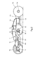
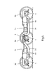
- the bogie has an overall H-shaped main frame 1, which is composed of a longitudinal beam 1 a lying in the direction of travel and two cross beams 1 b running parallel to one another, which are thus arranged transversely to the running direction of the bogie.
- the carriage body of the rail vehicle not shown in the drawing, is supported on the main frame 1 by means of a rotary socket bearing.
- the lower bearing part 1c of this rotary cup bearing can be seen in the drawing.
- Each wheel set 3 comprises an axle 3a which is provided with wheels 3b of small diameter and with its laterally projecting steering knuckles 3c in
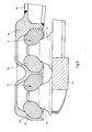
- Axle bearings 4 is rotatably mounted. As can be seen in particular in FIG. 3, between each axle bearing 4 and the associated side cheek 2a or 2b, a support 5 is arranged with a spherical bearing surface that enables adjustment that can be moved on all sides.
- spring elements are used as spring elements, the roller spring 6a of which consists of a ring made of rubber or plastic and is arranged between a lower spring plate 6b and an upper spring plate 6c.
- the roller spring 6a In addition to a spring travel in the vertical direction, such a design enables a limited movement of the side cheek 2a or 2b relative to the main frame 1 both in the longitudinal direction and in the transverse direction and also a movement at an angle to the longitudinal and transverse directions.
- the wheel sets 3 of the bogie have the possibility of automatically adapting to the respective rail course when passing through a curved track adapt.
- the construction described also ensures that the wheel sets 3 each return to the central position after passing through a curved track, so that the bogie ensures exact straight running.
- the center of support of the spring elements 6 arranged in pairs on the side cheeks 2a and 2b lies at a distance of one third of the center distance from the outer axis 3a and at a distance of two thirds of the center distance from the central axis 3a, so that all three axes 3a of the bogie each are loaded with about a third of the bogie load and accordingly all the wheels 3b of the bogie stand on the rails with approximately the same pressure.
- the respective inner ends of the side cheeks 2a and 2b are jointly supported on the axle bearing 4 of the central axle 3a, as can be seen not only in the top view in FIG. 1, but also in particular in FIG. 2.
- This common support of the respective inner ends of the side cheeks 2a and 2b on the axle bearing 4 of the central axle 3a provides, on the one hand, for a uniform axle load distribution and, on the other hand, is a prerequisite for the three to be articulated with the side cheeks 2a and 4b via their axle bearings 4 2b connected axes 3a at cure can set ven mars relative to each other.
- the good running properties of the three-axle bogie achieved by the construction described above enable the use of wheels 3b with the smallest possible diameter.
- the wheels 3b for example, with a running circle diameter of only 450 mm, allow a very low overall height of the entire bogie of about 550 mm, so that the bogie can be used for rail freight cars for transporting road vehicles that have a very low height of the loading area above the Require the top edge of the rail so that the road vehicles remain within the permissible profile for the rail freight wagons.
- the bogie in this context is the course of the crossbeam 1b of the main frame 1 transversely to the direction of rotation of the bogie, because this makes it possible for the crossbeams 1b of the main frame 1 to run between the wheel sets 3 in a lowered manner.
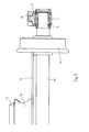
- the lower bearing part 1c of the rotary cup bearing is arranged within the main frame 1 in such a way that its bearing surface lies essentially below the upper edge of the main frame 1. This, together with a lowering of the side cheeks 2a and 2b in the area of the spring elements 6, enables the overall low overall height of the bogie of only about 550 mm.
Landscapes
- Mechanical Engineering (AREA)
- Engineering & Computer Science (AREA)
- Vehicle Body Suspensions (AREA)
- Signal Processing For Digital Recording And Reproducing (AREA)
- Transition And Organic Metals Composition Catalysts For Addition Polymerization (AREA)
- Lubricants (AREA)
- Springs (AREA)
- Road Paving Structures (AREA)
- Medicines Containing Material From Animals Or Micro-Organisms (AREA)
- Fittings On The Vehicle Exterior For Carrying Loads, And Devices For Holding Or Mounting Articles (AREA)
- Automatic Cycles, And Cycles In General (AREA)
- Support Of The Bearing (AREA)
- Platform Screen Doors And Railroad Systems (AREA)
- Carriers, Traveling Bodies, And Overhead Traveling Cranes (AREA)
- Vehicle Waterproofing, Decoration, And Sanitation Devices (AREA)
- Vibration Prevention Devices (AREA)
- Silver Salt Photography Or Processing Solution Therefor (AREA)
- Lasers (AREA)
- Medicines Containing Antibodies Or Antigens For Use As Internal Diagnostic Agents (AREA)
Priority Applications (1)
| Application Number | Priority Date | Filing Date | Title |
|---|---|---|---|
| AT83106790T ATE55579T1 (de) | 1982-08-10 | 1983-07-11 | Dreiachsiges drehgestell fuer schienenfahrzeuge. |
Applications Claiming Priority (2)
| Application Number | Priority Date | Filing Date | Title |
|---|---|---|---|
| DE3229709 | 1982-08-10 | ||
| DE3229709A DE3229709C1 (de) | 1982-08-10 | 1982-08-10 | Dreiachsiges Drehgestell fuer Schienenfahrzeuge |
Publications (3)
| Publication Number | Publication Date |
|---|---|
| EP0100893A2 true EP0100893A2 (fr) | 1984-02-22 |
| EP0100893A3 EP0100893A3 (en) | 1986-01-08 |
| EP0100893B1 EP0100893B1 (fr) | 1990-08-16 |
Family
ID=6170501
Family Applications (1)
| Application Number | Title | Priority Date | Filing Date |
|---|---|---|---|
| EP83106790A Expired - Lifetime EP0100893B1 (fr) | 1982-08-10 | 1983-07-11 | Boggie à trois essieux pour véhicules ferroviaires |
Country Status (9)
| Country | Link |
|---|---|
| EP (1) | EP0100893B1 (fr) |
| AT (1) | ATE55579T1 (fr) |
| DD (1) | DD210239A5 (fr) |
| DE (1) | DE3229709C1 (fr) |
| DK (1) | DK166314C (fr) |
| ES (1) | ES282212Y (fr) |
| NO (1) | NO157053C (fr) |
| PL (1) | PL142531B1 (fr) |
| YU (1) | YU43549B (fr) |
Cited By (1)
| Publication number | Priority date | Publication date | Assignee | Title |
|---|---|---|---|---|
| EP1992540A2 (fr) | 2007-05-15 | 2008-11-19 | Siemens Aktiengesellschaft | Véhicule ferroviaire à deux étages |
Families Citing this family (5)
| Publication number | Priority date | Publication date | Assignee | Title |
|---|---|---|---|---|
| JPH0659827B2 (ja) * | 1987-10-21 | 1994-08-10 | 株式会社日立製作所 | 車両用軸ばね装置 |
| DE19508589A1 (de) * | 1994-03-13 | 1996-11-28 | Josef Nusser | Laufwerk für Schienenfahrzeuge |
| RU2745709C1 (ru) * | 2020-08-27 | 2021-03-30 | Акционерное общество «Научно-производственная корпорация «Уралвагонзавод» имени Ф.Э. Дзержинского» | Трехосная тележка с балансирами (варианты) |
| RU2769031C1 (ru) * | 2021-08-25 | 2022-03-28 | Акционерное общество «Научно-производственная корпорация «Уралвагонзавод» имени Ф.Э. Дзержинского» | Колесная пара трехосной тележки грузового железнодорожного вагона |
| RU2769028C1 (ru) * | 2021-08-25 | 2022-03-28 | Акционерное общество «Научно-производственная корпорация «Уралвагонзавод» имени Ф.Э. Дзержинского» | Колесная пара трехосной тележки грузового железнодорожного вагона |
Family Cites Families (2)
| Publication number | Priority date | Publication date | Assignee | Title |
|---|---|---|---|---|
| DE1178886B (de) * | 1959-05-27 | 1964-10-01 | Henschel Werke Ag | Anordnung der Federn und Ausgleichhebel an einem dreiachsigen Drehgestell |
| DE2919635C2 (de) * | 1979-05-16 | 1982-12-02 | Waggonfabrik Talbot, 5100 Aachen | Vierachsiges Drehgestell |
-
1982
- 1982-08-10 DE DE3229709A patent/DE3229709C1/de not_active Expired
-
1983
- 1983-07-11 EP EP83106790A patent/EP0100893B1/fr not_active Expired - Lifetime
- 1983-07-11 AT AT83106790T patent/ATE55579T1/de active
- 1983-08-03 YU YU1615/83A patent/YU43549B/xx unknown
- 1983-08-05 DK DK359183A patent/DK166314C/da not_active IP Right Cessation
- 1983-08-08 DD DD83253798A patent/DD210239A5/de not_active IP Right Cessation
- 1983-08-09 ES ES1983282212U patent/ES282212Y/es not_active Expired
- 1983-08-09 NO NO832860A patent/NO157053C/no unknown
- 1983-08-10 PL PL1983243373A patent/PL142531B1/pl unknown
Cited By (2)
| Publication number | Priority date | Publication date | Assignee | Title |
|---|---|---|---|---|
| EP1992540A2 (fr) | 2007-05-15 | 2008-11-19 | Siemens Aktiengesellschaft | Véhicule ferroviaire à deux étages |
| EP1992540A3 (fr) * | 2007-05-15 | 2010-02-03 | Siemens Aktiengesellschaft | Véhicule ferroviaire à deux étages |
Also Published As
| Publication number | Publication date |
|---|---|
| NO157053C (no) | 1988-01-13 |
| DK166314B (da) | 1993-04-05 |
| ES282212Y (es) | 1985-10-16 |
| EP0100893A3 (en) | 1986-01-08 |
| YU43549B (en) | 1989-08-31 |
| DD210239A5 (de) | 1984-06-06 |
| DE3229709C1 (de) | 1987-08-20 |
| DK359183D0 (da) | 1983-08-05 |
| EP0100893B1 (fr) | 1990-08-16 |
| PL142531B1 (en) | 1987-10-31 |
| DK166314C (da) | 1993-08-30 |
| DK359183A (da) | 1984-02-11 |
| ES282212U (es) | 1985-03-01 |
| YU161583A (en) | 1986-10-31 |
| PL243373A1 (en) | 1984-04-24 |
| NO832860L (no) | 1984-02-13 |
| ATE55579T1 (de) | 1990-09-15 |
| NO157053B (no) | 1987-10-05 |
Similar Documents
| Publication | Publication Date | Title |
|---|---|---|
| EP0565676B1 (fr) | Chassis pour wagons a plate-forme surbaissee | |
| EP0046210A2 (fr) | Chariot roulant | |
| DE3911138C2 (fr) | ||
| EP0135877B1 (fr) | Train de roulement pour véhicules ferroviaires | |
| EP0598353B1 (fr) | Train de roulement pour rames à plate-forme surbaissée | |
| EP0100893B1 (fr) | Boggie à trois essieux pour véhicules ferroviaires | |
| EP0443309B1 (fr) | Couplage de voitures | |
| EP0019265B1 (fr) | Bogie à quatre essieux | |
| DE19507021A1 (de) | Einzelradsatzdoppelfahrwerk für Eisenbahnfahrzeuge | |
| EP0193919B1 (fr) | Châssis de boggie pour véhicules ferroviaires | |
| EP0507146A1 (fr) | Véhicule ferroviaire notamment véhicule à plancher bas | |
| EP0439573B1 (fr) | Chassis pour vehicules surbaisses | |
| DE10047737A1 (de) | Schienenfahrgerät mit einem Lastträger | |
| DE1936932B2 (de) | Drehgestelle fuer schienenfahrzeuge mit einzelaufhaengung der radsaetze | |
| EP0410407B1 (fr) | Sous-châssis de roulement pour un véhicule ou un bogie ferroviaires | |
| EP0659626A1 (fr) | Train de roulement individuel pour véhicules ferroviaires | |
| AT398557B (de) | Fahrwerk für ein schienenfahrzeug, insbesondere niederflurfahrzeug | |
| DE2444013C3 (de) | Fahrgestell für Schwerlastschienenfahrzeuge, insbesondere Hüttenfahrzeuge | |
| DE10202241C1 (de) | Hochleistungsrichtgelenk | |
| DE2422226C3 (de) | Drehgestell mit verwindungsweichem, ecksteifem Rahmen für Hochgeschwindigkeits-Schienenfahrzeuge | |
| DE549735C (de) | Standbahn fuer hohe Geschwindigkeiten | |
| AT256165B (de) | Schienenfahrzeug mit tiefliegender Plattform | |
| DE10054203C2 (de) | Drehgestell für Schienenfahrzeuge | |
| DE4330951A1 (de) | Drehgestell, insbesondere für Zweiwegefahrzeuge | |
| DE2153866A1 (de) | Gelenkfahrzeug |
Legal Events
| Date | Code | Title | Description |
|---|---|---|---|
| PUAI | Public reference made under article 153(3) epc to a published international application that has entered the european phase |
Free format text: ORIGINAL CODE: 0009012 |
|
| AK | Designated contracting states |
Designated state(s): AT BE CH FR GB IT LI NL SE |
|
| PUAL | Search report despatched |
Free format text: ORIGINAL CODE: 0009013 |
|
| AK | Designated contracting states |
Designated state(s): AT BE CH FR GB IT LI NL SE |
|
| 17P | Request for examination filed |
Effective date: 19851115 |
|
| 17Q | First examination report despatched |
Effective date: 19860731 |
|
| GRAA | (expected) grant |
Free format text: ORIGINAL CODE: 0009210 |
|
| AK | Designated contracting states |
Kind code of ref document: B1 Designated state(s): AT BE CH FR GB IT LI NL SE |
|
| REF | Corresponds to: |
Ref document number: 55579 Country of ref document: AT Date of ref document: 19900915 Kind code of ref document: T |
|
| ET | Fr: translation filed | ||
| GBT | Gb: translation of ep patent filed (gb section 77(6)(a)/1977) | ||
| ITF | It: translation for a ep patent filed | ||
| PLBE | No opposition filed within time limit |
Free format text: ORIGINAL CODE: 0009261 |
|
| STAA | Information on the status of an ep patent application or granted ep patent |
Free format text: STATUS: NO OPPOSITION FILED WITHIN TIME LIMIT |
|
| ITTA | It: last paid annual fee | ||
| 26N | No opposition filed | ||
| EAL | Se: european patent in force in sweden |
Ref document number: 83106790.5 |
|
| PGFP | Annual fee paid to national office [announced via postgrant information from national office to epo] |
Ref country code: GB Payment date: 19950622 Year of fee payment: 13 |
|
| PGFP | Annual fee paid to national office [announced via postgrant information from national office to epo] |
Ref country code: FR Payment date: 19950717 Year of fee payment: 13 |
|
| PGFP | Annual fee paid to national office [announced via postgrant information from national office to epo] |
Ref country code: SE Payment date: 19950721 Year of fee payment: 13 Ref country code: NL Payment date: 19950721 Year of fee payment: 13 |
|
| PGFP | Annual fee paid to national office [announced via postgrant information from national office to epo] |
Ref country code: BE Payment date: 19950809 Year of fee payment: 13 |
|
| PG25 | Lapsed in a contracting state [announced via postgrant information from national office to epo] |
Ref country code: GB Effective date: 19960711 |
|
| PG25 | Lapsed in a contracting state [announced via postgrant information from national office to epo] |
Ref country code: SE Effective date: 19960712 |
|
| PGFP | Annual fee paid to national office [announced via postgrant information from national office to epo] |
Ref country code: AT Payment date: 19960719 Year of fee payment: 14 |
|
| PGFP | Annual fee paid to national office [announced via postgrant information from national office to epo] |
Ref country code: CH Payment date: 19960723 Year of fee payment: 14 |
|
| PG25 | Lapsed in a contracting state [announced via postgrant information from national office to epo] |
Ref country code: BE Effective date: 19960731 |
|
| BERE | Be: lapsed |
Owner name: WAGGONFABRIK TALBOT Effective date: 19960731 |
|
| PG25 | Lapsed in a contracting state [announced via postgrant information from national office to epo] |
Ref country code: NL Effective date: 19970201 |
|
| GBPC | Gb: european patent ceased through non-payment of renewal fee |
Effective date: 19960711 |
|
| PG25 | Lapsed in a contracting state [announced via postgrant information from national office to epo] |
Ref country code: FR Effective date: 19970328 |
|
| NLV4 | Nl: lapsed or anulled due to non-payment of the annual fee |
Effective date: 19970201 |
|
| EUG | Se: european patent has lapsed |
Ref document number: 83106790.5 |
|
| REG | Reference to a national code |
Ref country code: FR Ref legal event code: ST |
|
| PG25 | Lapsed in a contracting state [announced via postgrant information from national office to epo] |
Ref country code: AT Free format text: LAPSE BECAUSE OF NON-PAYMENT OF DUE FEES Effective date: 19970711 |
|
| PG25 | Lapsed in a contracting state [announced via postgrant information from national office to epo] |
Ref country code: LI Free format text: LAPSE BECAUSE OF NON-PAYMENT OF DUE FEES Effective date: 19970731 Ref country code: CH Free format text: LAPSE BECAUSE OF NON-PAYMENT OF DUE FEES Effective date: 19970731 |
|
| REG | Reference to a national code |
Ref country code: CH Ref legal event code: PL |