EP0100916B1 - Méthode et dispositif pour coder un signal d'image avec réduction de la redondance avec distorsion locale uniforme - Google Patents
Méthode et dispositif pour coder un signal d'image avec réduction de la redondance avec distorsion locale uniforme Download PDFInfo
- Publication number
- EP0100916B1 EP0100916B1 EP83106970A EP83106970A EP0100916B1 EP 0100916 B1 EP0100916 B1 EP 0100916B1 EP 83106970 A EP83106970 A EP 83106970A EP 83106970 A EP83106970 A EP 83106970A EP 0100916 B1 EP0100916 B1 EP 0100916B1
- Authority
- EP
- European Patent Office
- Prior art keywords
- block
- value
- coefficient
- circuit
- coefficients
- Prior art date
- Legal status (The legal status is an assumption and is not a legal conclusion. Google has not performed a legal analysis and makes no representation as to the accuracy of the status listed.)
- Expired
Links
Images


Classifications
-
- H—ELECTRICITY
- H04—ELECTRIC COMMUNICATION TECHNIQUE
- H04N—PICTORIAL COMMUNICATION, e.g. TELEVISION
- H04N19/00—Methods or arrangements for coding, decoding, compressing or decompressing digital video signals
- H04N19/10—Methods or arrangements for coding, decoding, compressing or decompressing digital video signals using adaptive coding
- H04N19/189—Methods or arrangements for coding, decoding, compressing or decompressing digital video signals using adaptive coding characterised by the adaptation method, adaptation tool or adaptation type used for the adaptive coding
- H04N19/192—Methods or arrangements for coding, decoding, compressing or decompressing digital video signals using adaptive coding characterised by the adaptation method, adaptation tool or adaptation type used for the adaptive coding the adaptation method, adaptation tool or adaptation type being iterative or recursive
-
- H—ELECTRICITY
- H04—ELECTRIC COMMUNICATION TECHNIQUE
- H04N—PICTORIAL COMMUNICATION, e.g. TELEVISION
- H04N19/00—Methods or arrangements for coding, decoding, compressing or decompressing digital video signals
- H04N19/10—Methods or arrangements for coding, decoding, compressing or decompressing digital video signals using adaptive coding
- H04N19/134—Methods or arrangements for coding, decoding, compressing or decompressing digital video signals using adaptive coding characterised by the element, parameter or criterion affecting or controlling the adaptive coding
- H04N19/146—Data rate or code amount at the encoder output
- H04N19/147—Data rate or code amount at the encoder output according to rate distortion criteria
-
- H—ELECTRICITY
- H04—ELECTRIC COMMUNICATION TECHNIQUE
- H04N—PICTORIAL COMMUNICATION, e.g. TELEVISION
- H04N19/00—Methods or arrangements for coding, decoding, compressing or decompressing digital video signals
- H04N19/10—Methods or arrangements for coding, decoding, compressing or decompressing digital video signals using adaptive coding
- H04N19/134—Methods or arrangements for coding, decoding, compressing or decompressing digital video signals using adaptive coding characterised by the element, parameter or criterion affecting or controlling the adaptive coding
- H04N19/146—Data rate or code amount at the encoder output
- H04N19/152—Data rate or code amount at the encoder output by measuring the fullness of the transmission buffer
-
- H—ELECTRICITY
- H04—ELECTRIC COMMUNICATION TECHNIQUE
- H04N—PICTORIAL COMMUNICATION, e.g. TELEVISION
- H04N19/00—Methods or arrangements for coding, decoding, compressing or decompressing digital video signals
- H04N19/10—Methods or arrangements for coding, decoding, compressing or decompressing digital video signals using adaptive coding
- H04N19/134—Methods or arrangements for coding, decoding, compressing or decompressing digital video signals using adaptive coding characterised by the element, parameter or criterion affecting or controlling the adaptive coding
- H04N19/154—Measured or subjectively estimated visual quality after decoding, e.g. measurement of distortion
-
- H—ELECTRICITY
- H04—ELECTRIC COMMUNICATION TECHNIQUE
- H04N—PICTORIAL COMMUNICATION, e.g. TELEVISION
- H04N19/00—Methods or arrangements for coding, decoding, compressing or decompressing digital video signals
- H04N19/10—Methods or arrangements for coding, decoding, compressing or decompressing digital video signals using adaptive coding
- H04N19/169—Methods or arrangements for coding, decoding, compressing or decompressing digital video signals using adaptive coding characterised by the coding unit, i.e. the structural portion or semantic portion of the video signal being the object or the subject of the adaptive coding
- H04N19/17—Methods or arrangements for coding, decoding, compressing or decompressing digital video signals using adaptive coding characterised by the coding unit, i.e. the structural portion or semantic portion of the video signal being the object or the subject of the adaptive coding the unit being an image region, e.g. an object
- H04N19/176—Methods or arrangements for coding, decoding, compressing or decompressing digital video signals using adaptive coding characterised by the coding unit, i.e. the structural portion or semantic portion of the video signal being the object or the subject of the adaptive coding the unit being an image region, e.g. an object the region being a block, e.g. a macroblock
-
- H—ELECTRICITY
- H04—ELECTRIC COMMUNICATION TECHNIQUE
- H04N—PICTORIAL COMMUNICATION, e.g. TELEVISION
- H04N19/00—Methods or arrangements for coding, decoding, compressing or decompressing digital video signals
- H04N19/10—Methods or arrangements for coding, decoding, compressing or decompressing digital video signals using adaptive coding
- H04N19/169—Methods or arrangements for coding, decoding, compressing or decompressing digital video signals using adaptive coding characterised by the coding unit, i.e. the structural portion or semantic portion of the video signal being the object or the subject of the adaptive coding
- H04N19/184—Methods or arrangements for coding, decoding, compressing or decompressing digital video signals using adaptive coding characterised by the coding unit, i.e. the structural portion or semantic portion of the video signal being the object or the subject of the adaptive coding the unit being bits, e.g. of the compressed video stream
-
- H—ELECTRICITY
- H04—ELECTRIC COMMUNICATION TECHNIQUE
- H04N—PICTORIAL COMMUNICATION, e.g. TELEVISION
- H04N19/00—Methods or arrangements for coding, decoding, compressing or decompressing digital video signals
- H04N19/60—Methods or arrangements for coding, decoding, compressing or decompressing digital video signals using transform coding
-
- H—ELECTRICITY
- H04—ELECTRIC COMMUNICATION TECHNIQUE
- H04N—PICTORIAL COMMUNICATION, e.g. TELEVISION
- H04N19/00—Methods or arrangements for coding, decoding, compressing or decompressing digital video signals
- H04N19/10—Methods or arrangements for coding, decoding, compressing or decompressing digital video signals using adaptive coding
- H04N19/102—Methods or arrangements for coding, decoding, compressing or decompressing digital video signals using adaptive coding characterised by the element, parameter or selection affected or controlled by the adaptive coding
- H04N19/13—Adaptive entropy coding, e.g. adaptive variable length coding [AVLC] or context adaptive binary arithmetic coding [CABAC]
-
- H—ELECTRICITY
- H04—ELECTRIC COMMUNICATION TECHNIQUE
- H04N—PICTORIAL COMMUNICATION, e.g. TELEVISION
- H04N19/00—Methods or arrangements for coding, decoding, compressing or decompressing digital video signals
- H04N19/10—Methods or arrangements for coding, decoding, compressing or decompressing digital video signals using adaptive coding
- H04N19/134—Methods or arrangements for coding, decoding, compressing or decompressing digital video signals using adaptive coding characterised by the element, parameter or criterion affecting or controlling the adaptive coding
- H04N19/146—Data rate or code amount at the encoder output
-
- H—ELECTRICITY
- H04—ELECTRIC COMMUNICATION TECHNIQUE
- H04N—PICTORIAL COMMUNICATION, e.g. TELEVISION
- H04N19/00—Methods or arrangements for coding, decoding, compressing or decompressing digital video signals
- H04N19/90—Methods or arrangements for coding, decoding, compressing or decompressing digital video signals using coding techniques not provided for in groups H04N19/10-H04N19/85, e.g. fractals
- H04N19/91—Entropy coding, e.g. variable length coding [VLC] or arithmetic coding
Definitions
- the present invention concerns signal coding systems. More particularly it related to a method and a device for coding an image signal with redundancy reduction with locally uniform distortion.
- a known coding technique to be applied to non-stationary portions of the image signal, consists of subdividing the whole image into blocks, applying a linear transformation of each block to obtain a set of coefficients, and coding each set of coefficients independently of the others.
- This technique is described for example in the article by H.C. Andrews, J. Kane, W. K. Pratt "Hadamard transform image coding” Proceedings IEEE, January 1969, pp 58 ⁇ 68, or in the article by A. Habibi, P. A. Wintz "Image coding by linear transformation and block quantization", IEEE Transactions on Communication Technology, vol. COM-19, February 1971, pp. 50-63.
- the quantization is intrinsically non-adaptive, and the problem of bit assignment to the coefficients is solved by using a Huffman encoder, after making a uniform quantization.
- the iteration is stopped when the total number of bits in a block has been assigned.
- This procedure implies that for coding, besides the coefficient value, also the information about the number of bits by which the coefficient is coded is to be supplied every time to the decoder which requirement makes the system rather inefficient.
- the described problems are solved by the method of the present invention, which method is characterized in that at each iteration the choice of the coefficient to be coded with the additional bit is carried out by using one out of K tables in each of which, depending on the total bit number already assigned to the block the index of said coefficient is written, and in that at each iteration a global error value is evaluated which global error is that made when reconstructing the block itself by using the total bit number already assigned to the block until that moment, the iterations relating
- Such method is a method with redundancy reduction with locally uniform distortion which, on the basis of the direct computation for each block of the reconstruction error, assigns for a block representation the specific bit number which renders the error made equal to the desired error, besides it does not require the coding according to each of the possible bit assignment tables (one per each number of bits used), but it uses an iterative method which constructs the assignment table with a number of coding steps, each of them involving an only coefficient, equal to the number of bits used for the representation of the block.
- the assignment tables were previously determined and are known both by the coder and the decoder, thus it will be sufficient to supply the decoder with the number of bits used for the block and the identity of the particular table.
- a further object of the present invention is a device designed to implement said method.
- a linear transformation is applied to the image signal, which has already been sampled according to the PCM (Pulse Code Modulation) technique and subdivided into successive portions or blocks, thus obtaining a set of new random variables or transformation coefficients from each block.
- Each set of coefficients is then coded independently of the others by assigning a variable number of bits.
- the coding is carried out iteratively by assigning at each iteration a bit to one of the coefficients of the block and directly evaluating at each iteration the global error made in the representation of the block with the present total number of bits.
- the iteration starts with the representation of all the coefficients of a block with zero bits and goes on till when the error becomes lower than a pre-determined threshold value.
- the coding procedure provides the following steps:
- the index of the coefficient to which at each iteration an additional bit is given is furnished a priori by a determined number K of tables, one per each value assumed by a parameter k depending on the energy distribution inside a block.
- the parameter k is computer as follows: first, each block is subdivided into K physical regions; then, the barycenter of the block, considered as a set consisting of various coefficients, is calculated. Said coefficients may be weighted by a function allotting a greater weight to the coefficient's relating to higher frequencies; the value of k is chosen (where 1-- ⁇ k-- ⁇ K) which corresponds to the region within which the calculated barycenter falls.
- Each block will be indicated by a particular value of k which will determine the choice of the particular table above. Whenever an additional bit is allotted to one of the coefficients, the total number of bits assigned to the block is the address for the chosen table.
- the coefficients of a block are further subdivided into groups, depending on the mean information amount contained in each of them.
- the maximum number of bits with which the coefficients can be coded during iterations varies according to the group they belong to.
- the number of sets used is KxS, where K is the above defined number of classes, and S the maximum value which may be assumed by the parameter s depending on the mean energy amount, that is the contrast of the block.
- the mean, absolute value of the coefficients of a block may vary, depending on the mean energy amount: the, the parameter s allows a better adjustment of the quantization procedure depending on the mean absolute value of the coefficients.
- a coding of the block will be obtained with a determined total number of bits suitably subdivided among the various coefficients (the coded value of each coefficient is as mentioned the index of the level of the quantization law chosen within which the transformed value of the coefficient itself is comprised). Said subdivision is used for a possible transmission operation of coded image blocks.
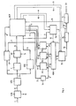
- STB provides in a known way at the output on wire 5, at the beginning of each image block, a reset signal for block SM which will be mentioned hereinafter.
- Connection 2 is connected to block DT2 which performs a two-dimensional transformation of samples of each block.
- the transform bases used in the two directions, that is along the lines and along the points, can be different and whatever; the operations carried out by the circuits down-stream DT2, as well as their configuration, are independent of the type of transform chosen.
- DT2 obtains for each block nxm coefficients Cij (with 1 ⁇ i ⁇ n; issjssm), each of them represented by the NB bits, which it serially supplies at the output on connection 3.
- Block QCN which will be explained in detail in connection with Fig. 2, codes the coefficients assigning a bit at a time to the various coefficients of the block, till when it verifies that the global representation error of the block is lower than a predetermined threshold.
- QCN executes a quantization operation on the coefficients, using S sets of quantization laws, which will be later referred to as quantizers, to have the best correspondence between the dynamics of the coefficients belonging to a block and the field of values that one of the sets covers.
- index L of such a coefficient in the block linearized by columns (L ⁇ j ⁇ n+i) is supplied by the same block QCN on connection 7 and forms the reading address of the buffer CB which supplies, on connection 8, QCN with the values of non-quantized coefficient.
- connection 16 is then connected to line buffer BL which is to adapt the non-uniform speed at which data are produced (non constant number of bits for coding a block) and supplied at its input on connection 16, to the constant speed at which data are then to be delivered to line CH through the connection 18 and the usual line interface IL.
- Block BL also supplies at the output 19 the information relating to its stuffing degree; said information is supplied to block QCN which uses it to modify the error threshold when the amount of data becomes incompatible with transmission speed and with the size of the line buffer used, as it will be better disclosed in connection with Fig. 2.
- Fig. 2 shows the circuit diagram of block QCN of Fig. 1.
- Circuit TS depending on the information on the stuffing degree of buffer BL (Fig. 1), which it receives on connection 19, selects for each image block a suitable threshold value of the admitted error representation of the block and delivers it on connection 22 to block DQC.
- the control of the amount of information produced per each block may depend on an absolute and/or differential measurement of the buffer state, i.e. on a measurement depending on the variation of the stuffing degree due to the presence of the data of the last coded blocks.
- TS can vary the data amount, produced per each block, from zero to NBmax bits.
- Block AG comprises a memory containing K terns of tables, where K is the number already defined of different energy distributions among the coefficients of a block.
- K is the number already defined of different energy distributions among the coefficients of a block.
- the respective number k supplied on connection 4, selects the tern of tables to be chosen. Then, when the enabling over wire 25 is present, AG uses that number k and the information read in the second table at position h, and in the third table at position L (with L given by the contents of the first table at position h) to calculate the address and the number of levels of quantizers to be used for the coding of the L-th coefficient both with the new and old bit assignment.
- the two data pairs are delivered at the output of AG in sequence on connection 26. Moreover, upon emission of the second pair of values on connection 26, AG emits on wire 29 an enable signal for outpus U, DE of block QAE.
- Block BAT comprises a memory of nxm positions. At each iteration said memory stores the present subdivision, among the various coefficients of a block, of the total bit number assigned to the block itself up to that moment.
- BAT also comprises an adder which increments by 1 the value stored in the L-th memory position, corresponding to the L-th coefficient, addressed by the bit configuration on connection 7, when present.
- BAT Upon reception of the enable signal on wire 13, BAT emits at the output on connection 12, the values stored in each position of its memory, with the same order by which coded efficients are transmitted on channel CH (Fig. 1). The contents of memory BAT is reset to zero, when the signal is present on wire 24.
- Wire 29 and connections 26 and 8 are connected to block QAE.
- QAE quantizes the L-th coefficient, arriving from connection 8, by using the S sets of quantizers already-defined, in the two cases in which the coefficient itself is coded with the new and old bit assignment.
- the S coded values of the quantized coefficient are sent on bus U.
- Bus DE consists of S connections on which the value is supplied, which is generally negative, of the difference between a function of the error made in representing the coefficient before and after the updating of the number of bits On the s-th connection the value is present corresponding to the coding of the block with the s-th set of quantizers.
- each circuit comprises memories in which K tables are written containing the values of the end points of quantizers used to quantize each coefficient; therefore each block QF comprises K sets of quantizers, where K is the above-defined number.
- the address on connection 26 identifies a determined quantizer of a determined family characterized by a determined number of levels; said number of levels being the same supplied as second information on connection 26.
- each block OF comprises a comparing circuit which compares at each iteration the coefficient present at the input on connection 8 with the values loaded in the memory, starting from the address supplied on connection 26, and for a maximum number of times indicated by the number of levels of the quantizer, which is present, as mentioned, on connection 26.
- Each OF separately and at the same time as the others carries out the same quantization operation (using its own families of quantizers) on the coefficient delivered at the input and supplies at the output the quantization interval index comprising the coefficient value.
- This index is represented by a constant bit number MB and represents the coded-coefficient value.
- Blocks AF consist of memories containing the values representing each of the quantization intervals, having a position in said memories in one-to-one correspondence with that of the end points of the quantization intervals contained in blocks QF1 ... QFS.
- the various quantized coefficients at the output of the blocks AF are represented by NB bits; then the connections cq1 ... cqS are composed each by NB wires.
- Connections cq1 ... cqS are connected to the respective first input of adders S1 ... SS which are all equal.
- the value of non-quantized coefficient present on connection 30 outgoing from block D3 is supplied to the second input of all the adders.
- D3 delays the information it receives at its input, through connection 8, by a time equal to that necessary to the circuits QF and AF to effect the quantization.
- Adders S1 ... SS execute the difference between the data received at their inputs, and supply the respective result, i.e. the difference between the values of the coefficient and the quantized coefficient, at the output on respective connections e1 ... eS, which are connected to blocks F1 ... FS, (equal to each other and of the same kind as block F of Fig. 1), which calculate the value of the error function due to each coefficient and deliver it at the output respectively on connections d1, d2, ... dS.
- These connections are respectively connected to delay circuits D41, D42,... D4S and to adders S11, S12. . . S1S.
- the delay introduced by D41 ... D4S is equal to the recurrence period of the addresses on connection 26.
- the second input of adders S11 ... S1S consists respectively of the outputs of D41 ... D4S.
- the outputs of S11 ... S1S are applied to the enabling circuit AB2 which receives the enabling signal on wire 29.
- the enabling circuit AB2 which receives the enabling signal on wire 29.
- connection 26 When, on the contrary, the second pair of values is present on connection 26, and the enabling signal is present on wire 29, the data on outputs of S11... S1S are delivered on the respective connections of bus DE; in this case said outputs represent the S differences of representation errors of the L-th coefficient quantized by NB(L)-1 bits taken with negative sign and afterwards NB(L) bits taken with positive sign.
- Connections q1 ... qS are also connected to the inputs of the enabling circuit AB1, which connects them to the respective connections of bus U, when the enabling signal on wire 29 is present.
- DQC is to decide whether to go or not with the iterations relating to a block, as already mentioned in connection with the description of Fig. 2; if it decides to go on, it supplies a pulse to block NBB through wire 23, and an enable signal to block AG through wire 25, if on the contrary, it decides to interrupt the iterations, it supplies an enable signal on wire 13 towards BAT (it happens if the error value on wire 21 becomes equal to or less than that supplied by TS on wire 22, of if the total number of bits of coding given to the block exceeds the maximum value NBmax).
- DQC interrupts the iterations relating to the block and emits the signal on wire 13 which is also delivered to IC (Fig. 1).
- IC supplies BL first of all with the information stored in OH, and then with the contents of the memory P which has been selected by the signal on wire 15 coming from OH; said signal having been delivered to OH by block MES of Fig. 2) (i.e. memory P is selected which contains the coded coefficient values allowing the minimum error).
Landscapes
- Engineering & Computer Science (AREA)
- Multimedia (AREA)
- Signal Processing (AREA)
- Compression, Expansion, Code Conversion, And Decoders (AREA)
- Compression Or Coding Systems Of Tv Signals (AREA)
Claims (12)
Applications Claiming Priority (2)
| Application Number | Priority Date | Filing Date | Title |
|---|---|---|---|
| IT6791882 | 1982-07-19 | ||
| IT67918/82A IT1155557B (it) | 1982-07-19 | 1982-07-19 | Metdodo e dispositivo per la codifica del segnale d immagine con riduzione di ridondanza a distorsione localmente uniforme |
Publications (3)
| Publication Number | Publication Date |
|---|---|
| EP0100916A2 EP0100916A2 (fr) | 1984-02-22 |
| EP0100916A3 EP0100916A3 (en) | 1985-11-06 |
| EP0100916B1 true EP0100916B1 (fr) | 1988-10-12 |
Family
ID=11306358
Family Applications (1)
| Application Number | Title | Priority Date | Filing Date |
|---|---|---|---|
| EP83106970A Expired EP0100916B1 (fr) | 1982-07-19 | 1983-07-15 | Méthode et dispositif pour coder un signal d'image avec réduction de la redondance avec distorsion locale uniforme |
Country Status (6)
| Country | Link |
|---|---|
| US (1) | US4581638A (fr) |
| EP (1) | EP0100916B1 (fr) |
| JP (1) | JPS5967789A (fr) |
| CA (1) | CA1246733A (fr) |
| DE (2) | DE100916T1 (fr) |
| IT (1) | IT1155557B (fr) |
Families Citing this family (36)
| Publication number | Priority date | Publication date | Assignee | Title |
|---|---|---|---|---|
| US4654484A (en) * | 1983-07-21 | 1987-03-31 | Interand Corporation | Video compression/expansion system |
| US5051991A (en) * | 1984-10-17 | 1991-09-24 | Ericsson Ge Mobile Communications Inc. | Method and apparatus for efficient digital time delay compensation in compressed bandwidth signal processing |
| FR2575351B1 (fr) * | 1984-12-21 | 1988-05-13 | Thomson Csf | Procede adaptatif de codage et de decodage d'une suite d'images par transformation, et dispositifs pour la mise en oeuvre de ce procede |
| US4661849A (en) * | 1985-06-03 | 1987-04-28 | Pictel Corporation | Method and apparatus for providing motion estimation signals for communicating image sequences |
| FR2589020B1 (fr) * | 1985-10-22 | 1987-11-20 | Eude Gerard | Procede de codage hybride par transformation pour la transmission de signaux d'image |
| JP2612557B2 (ja) * | 1985-12-18 | 1997-05-21 | ソニー株式会社 | データ伝送受信システム及びデータ復号装置 |
| EP0236519B1 (fr) * | 1986-03-08 | 1989-06-07 | ANT Nachrichtentechnik GmbH | Méthode d'interpolation de trame compensant le mouvement, utilisant un estimateur, structuré hiérarchiquement, de déplacement |
| US5007102A (en) * | 1986-03-20 | 1991-04-09 | At&T Bell Laboratories | Data compression using block list transform |
| JPS62222783A (ja) * | 1986-03-24 | 1987-09-30 | Kokusai Denshin Denwa Co Ltd <Kdd> | 動画像の高能率符号化方式 |
| US4776030A (en) * | 1986-03-28 | 1988-10-04 | Gte Laboratories Incorporated | Block quantizer for transform coding |
| EP0262460A3 (fr) * | 1986-09-30 | 1989-10-25 | Siemens Aktiengesellschaft | Dispositif d'attribution optimale de poids à des coefficients de transformation transmis auprès de codeurs par transformation dans le but de minimaliser les distorsions de repliement |
| US4920426A (en) * | 1986-11-10 | 1990-04-24 | Kokusai Denshin Denwa Co., Ltd. | Image coding system coding digital image signals by forming a histogram of a coefficient signal sequence to estimate an amount of information |
| DE3642492A1 (de) * | 1986-12-12 | 1988-06-23 | Bosch Gmbh Robert | Verfahren und schaltungsanordnung zur reduktion der datenrate digitalisierter bilder |
| US4816914A (en) * | 1987-01-07 | 1989-03-28 | Pictel Corporation | Method and apparatus for efficiently encoding and decoding image sequences |
| US4785356A (en) * | 1987-04-24 | 1988-11-15 | International Business Machines Corporation | Apparatus and method of attenuating distortion introduced by a predictive coding image compressor |
| US4849810A (en) * | 1987-06-02 | 1989-07-18 | Picturetel Corporation | Hierarchial encoding method and apparatus for efficiently communicating image sequences |
| US6563875B2 (en) | 1987-12-30 | 2003-05-13 | Thomson Licensing S.A. | Adaptive method of encoding and decoding a series of pictures by transformation, and devices for implementing this method |
| US5162923A (en) * | 1988-02-22 | 1992-11-10 | Canon Kabushiki Kaisha | Method and apparatus for encoding frequency components of image information |
| JPH0683375B2 (ja) * | 1988-04-05 | 1994-10-19 | 大日本スクリーン製造株式会社 | 圧縮化画像データのブロック歪除去装置 |
| US4910608A (en) * | 1988-12-09 | 1990-03-20 | Harris Corporation | Imagery data compression mechanism employing adaptive vector quantizer |
| US5249066A (en) * | 1989-02-14 | 1993-09-28 | Fujitsu Limited | Method and system for writing and reading coded data |
| US5121216A (en) * | 1989-07-19 | 1992-06-09 | Bell Communications Research | Adaptive transform coding of still images |
| US5038390A (en) * | 1990-06-05 | 1991-08-06 | Kabushiki Kaisha Toshiba | Method of transform data compression using save-maps |
| US6915014B1 (en) | 1990-07-31 | 2005-07-05 | Canon Kabushiki Kaisha | Image processing apparatus and method |
| DE69130275T2 (de) | 1990-07-31 | 1999-04-08 | Canon K.K., Tokio/Tokyo | Verfahren und Gerät zur Bildverarbeitung |
| US5049992A (en) * | 1990-08-27 | 1991-09-17 | Zenith Electronics Corporation | HDTV system with receivers operable at different levels of resolution |
| US5115309A (en) * | 1990-09-10 | 1992-05-19 | At&T Bell Laboratories | Method and apparatus for dynamic channel bandwidth allocation among multiple parallel video coders |
| US5454051A (en) * | 1991-08-05 | 1995-09-26 | Eastman Kodak Company | Method of reducing block artifacts created by block transform compression algorithms |
| JP3105335B2 (ja) * | 1992-02-07 | 2000-10-30 | 株式会社ハドソン | 画像の直交変換符号化による圧縮・伸張方法 |
| US5734677A (en) * | 1995-03-15 | 1998-03-31 | The Chinese University Of Hong Kong | Method for compression of loss-tolerant video image data from multiple sources |
| US5956430A (en) * | 1996-02-19 | 1999-09-21 | Fuji Xerox Co., Ltd. | Image information coding apparatus and method using code amount of a selected pixel block for changing coding parameter |
| JPH1032495A (ja) * | 1996-07-18 | 1998-02-03 | Sony Corp | データ処理装置および方法 |
| FR2779600B1 (fr) * | 1998-06-08 | 2000-07-13 | Alsthom Cge Alcatel | Dispositif pour la compression et la transmission de donnees, notamment d'images numeriques, sur un canal a debit constant |
| EP1538844A3 (fr) * | 2003-11-26 | 2006-05-31 | Samsung Electronics Co., Ltd. | Procédé pour la transformation et le codage d'une image couleur résiduelle |
| KR100647294B1 (ko) | 2004-11-09 | 2006-11-23 | 삼성전자주식회사 | 화상 데이터 부호화 및 복호화 방법 및 장치 |
| KR20060042295A (ko) * | 2004-11-09 | 2006-05-12 | 삼성전자주식회사 | 화상 데이터 부호화 및 복호화 방법 및 장치 |
Family Cites Families (7)
| Publication number | Priority date | Publication date | Assignee | Title |
|---|---|---|---|---|
| US3984626A (en) * | 1975-08-01 | 1976-10-05 | Bell Telephone Laboratories, Incorporated | Picture signal coder |
| US4189748A (en) * | 1977-08-23 | 1980-02-19 | Northrop Corporation | Video bandwidth reduction system using a two-dimensional transformation, and an adaptive filter with error correction |
| US4268861A (en) * | 1978-09-18 | 1981-05-19 | Massachusetts Institute Of Technology | Image coding |
| FR2443769A2 (fr) * | 1978-12-08 | 1980-07-04 | Telediffusion Fse | Compression et expansion (quantification) de signaux numeriques de television a codage differentiel |
| US4242733A (en) * | 1979-08-27 | 1980-12-30 | Northrop Corporation | Image spot detector using Haar coefficients |
| US4242734A (en) * | 1979-08-27 | 1980-12-30 | Northrop Corporation | Image corner detector using Haar coefficients |
| US4447886A (en) * | 1981-07-31 | 1984-05-08 | Meeker G William | Triangle and pyramid signal transforms and apparatus |
-
1982
- 1982-07-19 IT IT67918/82A patent/IT1155557B/it active
-
1983
- 1983-07-07 JP JP58122471A patent/JPS5967789A/ja active Pending
- 1983-07-15 EP EP83106970A patent/EP0100916B1/fr not_active Expired
- 1983-07-15 DE DE198383106970T patent/DE100916T1/de active Pending
- 1983-07-15 DE DE8383106970T patent/DE3378246D1/de not_active Expired
- 1983-07-18 CA CA000432675A patent/CA1246733A/fr not_active Expired
- 1983-07-19 US US06/515,362 patent/US4581638A/en not_active Expired - Fee Related
Also Published As
| Publication number | Publication date |
|---|---|
| IT8267918A0 (it) | 1982-07-19 |
| DE3378246D1 (en) | 1988-11-17 |
| EP0100916A2 (fr) | 1984-02-22 |
| JPS5967789A (ja) | 1984-04-17 |
| IT8267918A1 (it) | 1984-01-19 |
| IT1155557B (it) | 1987-01-28 |
| DE100916T1 (de) | 1986-03-20 |
| EP0100916A3 (en) | 1985-11-06 |
| US4581638A (en) | 1986-04-08 |
| CA1246733A (fr) | 1988-12-13 |
Similar Documents
| Publication | Publication Date | Title |
|---|---|---|
| EP0100916B1 (fr) | Méthode et dispositif pour coder un signal d'image avec réduction de la redondance avec distorsion locale uniforme | |
| EP0123456B1 (fr) | Méthode de transformation-codage intratrame et intertrame combinée | |
| US4933883A (en) | Probability adaptation for arithmetic coders | |
| EP0470773B1 (fr) | Système de codage par transformation orthogonale | |
| EP0345871B1 (fr) | Dispositif pour reproduire des images vidéo numérisées avec une restauration d'erreurs à plan incliné | |
| US5892549A (en) | Method and apparatus for compressing a digital signal using vector quantization | |
| GB2308770A (en) | Error concealment using image gradients | |
| CA2216605A1 (fr) | Procede et systeme de representation d'un ensemble de donnees avec fonction de transformation de donnees et masque de donnees | |
| US5721543A (en) | System and method for modeling discrete data sequences | |
| JPH05276501A (ja) | 可変長の適応映像圧縮方法及び装置 | |
| US20160316204A1 (en) | Method and system for image compression using image block characteristics | |
| US4876595A (en) | Device for reproducing digitized video pictures using an improved restoration method | |
| US7379868B2 (en) | Method and apparatus for differential compression of speaker models | |
| JP4336745B2 (ja) | ダイナミックレンジが広い信号の無損失圧縮方法 | |
| EP0547826A1 (fr) | Compresseur ADPCH (MICDA) à nombre de bits adaptatif pour des données d'images | |
| Aizawa et al. | Adaptive discrete cosine transform coding with vector quantization for color images | |
| US4519085A (en) | Differential data coding and decoding process and system restricting propagation of transmission errors | |
| US4875094A (en) | Method of and device for estimating motion in a sequence of pictures | |
| JPH0427733B2 (fr) | ||
| CN115474035A (zh) | 点云属性编码方法、装置、解码方法、装置及相关设备 | |
| EP0834833A2 (fr) | Méthode pour tester la convergence dans un codage fractal d'image | |
| Bowling et al. | Motion compensated image coding with a combined maximum a posteriori and regression algorithm | |
| Hartenstein et al. | A comparative study of L1 distortion limited image compression algorithms | |
| Tzou | A fast computational approach to the design of block quantization | |
| Chien et al. | Suboptimal quantization control employing approximate distortion-rate relations for motion video coding |
Legal Events
| Date | Code | Title | Description |
|---|---|---|---|
| PUAI | Public reference made under article 153(3) epc to a published international application that has entered the european phase |
Free format text: ORIGINAL CODE: 0009012 |
|
| AK | Designated contracting states |
Designated state(s): DE FR GB NL SE |
|
| PUAL | Search report despatched |
Free format text: ORIGINAL CODE: 0009013 |
|
| AK | Designated contracting states |
Designated state(s): DE FR GB NL SE |
|
| EL | Fr: translation of claims filed | ||
| 17P | Request for examination filed |
Effective date: 19851024 |
|
| DET | De: translation of patent claims | ||
| 17Q | First examination report despatched |
Effective date: 19870630 |
|
| ITF | It: translation for a ep patent filed | ||
| GRAA | (expected) grant |
Free format text: ORIGINAL CODE: 0009210 |
|
| AK | Designated contracting states |
Kind code of ref document: B1 Designated state(s): DE FR GB NL SE |
|
| REF | Corresponds to: |
Ref document number: 3378246 Country of ref document: DE Date of ref document: 19881117 |
|
| ET | Fr: translation filed | ||
| PLBE | No opposition filed within time limit |
Free format text: ORIGINAL CODE: 0009261 |
|
| STAA | Information on the status of an ep patent application or granted ep patent |
Free format text: STATUS: NO OPPOSITION FILED WITHIN TIME LIMIT |
|
| 26N | No opposition filed | ||
| PGFP | Annual fee paid to national office [announced via postgrant information from national office to epo] |
Ref country code: SE Payment date: 19910610 Year of fee payment: 9 |
|
| PGFP | Annual fee paid to national office [announced via postgrant information from national office to epo] |
Ref country code: GB Payment date: 19910703 Year of fee payment: 9 |
|
| PGFP | Annual fee paid to national office [announced via postgrant information from national office to epo] |
Ref country code: DE Payment date: 19910730 Year of fee payment: 9 |
|
| PGFP | Annual fee paid to national office [announced via postgrant information from national office to epo] |
Ref country code: NL Payment date: 19910731 Year of fee payment: 9 Ref country code: FR Payment date: 19910731 Year of fee payment: 9 |
|
| PG25 | Lapsed in a contracting state [announced via postgrant information from national office to epo] |
Ref country code: GB Effective date: 19920715 |
|
| PG25 | Lapsed in a contracting state [announced via postgrant information from national office to epo] |
Ref country code: SE Effective date: 19920716 |
|
| PG25 | Lapsed in a contracting state [announced via postgrant information from national office to epo] |
Ref country code: NL Effective date: 19930201 |
|
| NLV4 | Nl: lapsed or anulled due to non-payment of the annual fee | ||
| GBPC | Gb: european patent ceased through non-payment of renewal fee |
Effective date: 19920715 |
|
| PG25 | Lapsed in a contracting state [announced via postgrant information from national office to epo] |
Ref country code: FR Effective date: 19930331 |
|
| PG25 | Lapsed in a contracting state [announced via postgrant information from national office to epo] |
Ref country code: DE Effective date: 19930401 |
|
| REG | Reference to a national code |
Ref country code: FR Ref legal event code: ST |
|
| EUG | Se: european patent has lapsed |
Ref document number: 83106970.3 Effective date: 19930204 |