EP0100937A1 - Récipient mélangeur - Google Patents
Récipient mélangeur Download PDFInfo
- Publication number
- EP0100937A1 EP0100937A1 EP83107117A EP83107117A EP0100937A1 EP 0100937 A1 EP0100937 A1 EP 0100937A1 EP 83107117 A EP83107117 A EP 83107117A EP 83107117 A EP83107117 A EP 83107117A EP 0100937 A1 EP0100937 A1 EP 0100937A1
- Authority
- EP
- European Patent Office
- Prior art keywords
- mixing
- pestle
- cushion
- foil
- container according
- Prior art date
- Legal status (The legal status is an assumption and is not a legal conclusion. Google has not performed a legal analysis and makes no representation as to the accuracy of the status listed.)
- Granted
Links
- 238000002156 mixing Methods 0.000 title claims abstract description 79
- 239000011888 foil Substances 0.000 claims abstract description 47
- 238000004519 manufacturing process Methods 0.000 claims abstract description 8
- 238000002360 preparation method Methods 0.000 claims abstract description 6
- 239000000126 substance Substances 0.000 claims description 37
- 230000009969 flowable effect Effects 0.000 claims description 23
- 238000005192 partition Methods 0.000 claims description 13
- 229910000497 Amalgam Inorganic materials 0.000 claims description 6
- 238000003860 storage Methods 0.000 claims description 4
- 229910052782 aluminium Inorganic materials 0.000 claims description 3
- XAGFODPZIPBFFR-UHFFFAOYSA-N aluminium Chemical compound [Al] XAGFODPZIPBFFR-UHFFFAOYSA-N 0.000 claims description 3
- 230000000295 complement effect Effects 0.000 claims description 3
- 239000012815 thermoplastic material Substances 0.000 claims 1
- 230000006378 damage Effects 0.000 abstract description 2
- 239000007788 liquid Substances 0.000 abstract 1
- 239000012254 powdered material Substances 0.000 abstract 1
- QSHDDOUJBYECFT-UHFFFAOYSA-N mercury Chemical compound [Hg] QSHDDOUJBYECFT-UHFFFAOYSA-N 0.000 description 5
- 229910052753 mercury Inorganic materials 0.000 description 5
- 229910052751 metal Inorganic materials 0.000 description 5
- 239000002184 metal Substances 0.000 description 5
- 238000000034 method Methods 0.000 description 4
- 230000008569 process Effects 0.000 description 4
- 238000003805 vibration mixing Methods 0.000 description 4
- 239000000463 material Substances 0.000 description 3
- 239000004033 plastic Substances 0.000 description 3
- BQCADISMDOOEFD-UHFFFAOYSA-N Silver Chemical compound [Ag] BQCADISMDOOEFD-UHFFFAOYSA-N 0.000 description 2
- 230000009471 action Effects 0.000 description 2
- 239000000203 mixture Substances 0.000 description 2
- 239000000843 powder Substances 0.000 description 2
- 229920001169 thermoplastic Polymers 0.000 description 2
- 239000004416 thermosoftening plastic Substances 0.000 description 2
- BPQQTUXANYXVAA-UHFFFAOYSA-N Orthosilicate Chemical compound [O-][Si]([O-])([O-])[O-] BPQQTUXANYXVAA-UHFFFAOYSA-N 0.000 description 1
- 229910019142 PO4 Inorganic materials 0.000 description 1
- 230000001133 acceleration Effects 0.000 description 1
- 150000007942 carboxylates Chemical class 0.000 description 1
- 239000004568 cement Substances 0.000 description 1
- 238000006243 chemical reaction Methods 0.000 description 1
- 238000010276 construction Methods 0.000 description 1
- 239000003479 dental cement Substances 0.000 description 1
- 239000011521 glass Substances 0.000 description 1
- 230000003647 oxidation Effects 0.000 description 1
- 238000007254 oxidation reaction Methods 0.000 description 1
- NBIIXXVUZAFLBC-UHFFFAOYSA-K phosphate Chemical compound [O-]P([O-])([O-])=O NBIIXXVUZAFLBC-UHFFFAOYSA-K 0.000 description 1
- 239000010452 phosphate Substances 0.000 description 1
- 230000002028 premature Effects 0.000 description 1
- 230000009467 reduction Effects 0.000 description 1
- 238000000926 separation method Methods 0.000 description 1
Images
Classifications
-
- A—HUMAN NECESSITIES
- A61—MEDICAL OR VETERINARY SCIENCE; HYGIENE
- A61C—DENTISTRY; APPARATUS OR METHODS FOR ORAL OR DENTAL HYGIENE
- A61C5/00—Filling or capping teeth
- A61C5/60—Devices specially adapted for pressing or mixing capping or filling materials, e.g. amalgam presses
- A61C5/66—Capsules for filling material
-
- Y—GENERAL TAGGING OF NEW TECHNOLOGICAL DEVELOPMENTS; GENERAL TAGGING OF CROSS-SECTIONAL TECHNOLOGIES SPANNING OVER SEVERAL SECTIONS OF THE IPC; TECHNICAL SUBJECTS COVERED BY FORMER USPC CROSS-REFERENCE ART COLLECTIONS [XRACs] AND DIGESTS
- Y10—TECHNICAL SUBJECTS COVERED BY FORMER USPC
- Y10S—TECHNICAL SUBJECTS COVERED BY FORMER USPC CROSS-REFERENCE ART COLLECTIONS [XRACs] AND DIGESTS
- Y10S366/00—Agitating
- Y10S366/602—Amalgam mixer, e.g. dental filling
Definitions
- the invention relates to a mixing container for the separate storage and mixing of mutually reactive substances for the production of dental preparations, in particular amalgams.
- Known mixing vessel of this type (see.
- a flowable substance is separated from the mixing chamber by a partition.
- the partition is usually part of a destructible foil cushion in which the flowable substance, for example mercury, is sealed and which lies tightly against a perforated separation between the container parts. Moving the container parts against each other can destroy the foil cushion, creating a connection between the two chambers.
- the flowable substance is injected into the mixing chamber and thoroughly mixed there with the powdery substance, which can preferably be done by clamping the mixing container in the fork of an automatic vibratory mixing device, a so-called amalgam mixer.
- Mixing containers of the type defined above are also known which contain a movable elongate pestle in the mixing chamber.
- a mixing container is described for example in DE-OS 29 31 262.
- the partition is in this case designed as a movable, flexible partition in the form of a disk or a stopper, the edge of the partition sealingly abutting the inner wall of the first container part. Since the flowable substance is not sealed in a film, safe, separate storage of the substances that react with one another cannot be guaranteed.
- the pestle in the mixing chamber drives the separating element against the cover wall and serves to mix the two substances after the flowable substance has been transferred into the mixing chamber.
- Another mixing container of this type which is described in DE-OS 15 66 222, contains two container parts separated by a separating film and displaceable relative to one another, in which a flowable or a powdery substance (mercury or metal powder) is located.
- a flowable or a powdery substance cury or metal powder
- there is a pestle which, when the container parts are pushed together, tears or cuts the separating film provided with lines of weakness, as a result of which the metal powder can combine with the mercury.
- Such a mixing container has the disadvantage that the flowable substance cannot be enclosed in an absolutely gas-tight manner and that the separating film can tear even when the container parts are inadvertently moved against one another. In addition, residues of the separating film can get into the finished mixture.
- the invention has for its object to provide a mixing container of the type defined above are available, which is of simple construction, in which the flowable f ähige substance is supported entirely safe prior to use and a quantitative conversion of the flowable substance in the mixing chamber and a allows thorough mixing of the substances in the mixing chamber. Furthermore, no additional. 'Instrument for quantitative transfer of the flowable substance may be required more.
- the invention thus relates to a mixing container for the separate storage and mixing of substances which react with one another for the production of dental preparations, in particular amalgams, comprising a first container part in the form of a mixing chamber in which there is a generally powdery substance and a second, removable one Part of the container in which a flowable substance is located, separated from the mixing chamber by a partition, and an elongated pestle movable in the mixing chamber.
- This mixing container is characterized in that the dividing wall represents the wall of a destructible foil cushion filled with the flowable substance and arranged in the second container part facing the mixing chamber, and in that the tear resistance of the foil cushion and the size of the pressure pulse which the pestle shakes when mixing container is in one Vibration mixer receives, are coordinated so that the foil cushion is destroyed when hitting the pestle.
- the tensile strength of the destructible foil cushion is determined by the thickness and the material properties (e.g. elasticity, brittleness, etc.) and can also be influenced, for example, by providing the dividing wall of the foil cushion facing the mixing chamber with a predetermined breaking point.
- pressure pulse is chosen somewhat arbitrarily based on the physical term “pulse”. He is one Function of the mass of the pestle, the (negative) acceleration of the pestle when it hits the foil pillow and the time during which the pestle acts on the foil pillow. The latter two parameters are determined by the vibration mixing device used in each case. If the vibration mixing device moves quickly and with a high amplitude, the force that a pestle exerts on the foil cushion when it is braked when it hits it is greater than when using a slow-running mixing device with a low vibration amplitude. The time of action of the pestle on the foil cushion essentially depends on the duration of the vibration mixing process and the vibration frequency of the device.
- the size of the pressure pulse exerted by the pestle on the foil cushion is also an inverse function of the face.
- the pressure pulse can be increased in that the pestle is provided with an elevation, preferably with a tip, on the end face facing the film cushion, which can also be conical.
- the pressure pulse is reduced when the pestle hits the foil cushion with a larger area. In this case, either the mass of the pestle and / or the speed, the amplitude, the frequency or the duration of the oscillating movement must be increased in order to destroy a film cushion with the same film thickness and the same material properties.
- the P istill initially acts as a striking tool. Due to the violent swinging movement, the pestle hits the foil cushion several times, whereby the flowable substance is completely transferred into the mixing chamber. The transfer is more effective than when, as in the known isch variousern M, the container parts are moved towards each other only once, since the content of the film cushion is squeezed by the quantitative multiple flapping movements of the pestle. Since in the mixing container according to the invention there is no movement of the container parts against one another for the purpose of destroying the foil cushion, an unintentional, premature destruction is not possible, ie the foil cushion can only be destroyed if the pestle is thrown against the foil cushion with great force in an oscillating mixing device.
- the pestle After transferring the flowable substance into the mixing chamber, the pestle also functions as a mixing instrument.
- the pestle In order to facilitate targeted movement of the pestle, it is provided with guide elements at least in the end region facing the film cushion.
- the guide elements preferably represent radial ribs.
- the end face of the pestle facing the partition of the foil cushion is preferably complementary to the inner end wall of the second container part. If, for example, the inner end wall of the second container part is curved concavely, the corresponding side of the pestle is curved convexly. In this way, the time required to transfer the flowable substance into the mixing chamber is reduced.
- the apex surfaces of the ribs form the impact surfaces acting on the separating film.
- the pestle can also be designed as a simple cylindrical body or as a cylindrical body with a full head part, the striking surface acting on the separating film being curved if the inner end wall of the second container part is curved accordingly.
- the mixing container according to the invention preferably has an inner diameter of approximately 7 to 10 mm, in particular approximately 9 mm, and a total length of approximately 30 to 36 mm, in particular approximately 31 mm.
- the second cap-shaped container part with the foil cushion is put on the first container part in such a way that the edges of the foil cushion between the two container parts, i.e. come to rest between the wall of the second container part and the first container part, as a result of which the film cushion is firmly clamped.
- This arrangement has several advantages over an arrangement in which the flowable substance is squeezed out over a rigid perforated partition; e.g. the flowable substance can escape more easily after opening the foil cushion. Due to the blows of the pestle, the foil cushion is pressed firmly against the cap-shaped container part after mixing and can be removed together with it.
- the mixed dental preparation is not contaminated; Any film residues are pressed by the pestle against the second cap-shaped container part, which can be pulled off together with the teaching film cushion.
- the end wall of the first container part can be curved; however, it is preferably straight. In this case, the side of the pestle facing the end wall is straight, so that the pestle moves in a straight line during the mixing process.
- the largest diameter of the pestle which is given by the ribs in the preferred embodiment, is to be dimensioned such that the pestle can just be moved freely during the shaking movement.
- Preferred diameters are those which are 30 to 5%, in particular 15 to 10% smaller than the inner diameter of the mixing container.
- the guidance of the pestle can also be achieved by an appropriate design of the second cap-shaped container part. ;
- the length of the pestle also depends on the inside diameter of the mixing container.
- the minimum length is considered to be one that corresponds to the inside diameter of the mixing container, since a shorter length dimension no longer guarantees guidance.
- the maximum length of the pestle depends on the inner length of the mixing container.
- the maximum length of the pestle is about 10 to 60, preferably about 20 to 40% of the inner length of the mixing container.
- the guide elements represent radial ribs
- these are attached to the head part of the pestle, which faces the film cushion.
- the guidance of the pestle is improved by four or more ribs.
- Point-shaped or differently designed guide elements are also possible.
- the elevation provided on the end face of the pestle is preferably designed as a mandrel, cone or tip. It makes opening the foil cushion easier.
- the length of this survey depends on the thickness of the filled foil cushion, which should not be exceeded. The minimum length of the survey should be at least as large as the thickness of the release film.
- the length of the elevation of the pestle is usually 0.5 to 3 mm, preferably 1 to 2 mm.
- the material for the pestle is basically metal, glass or plastic.
- a plastic is preferably used which must have a sufficiently high impact strength to withstand the shaking movements of the mixing device.
- the flowable substance is located directly in the cap-shaped second container part in a foil cushion.
- a foil cushion can consist of metal or plastic foil, preferably metal foils coated with thermoplastic, in particular aluminum foils, are used.
- the dividing walls of the foil cushions are welded together at the edges.
- the preferred foil cushions are completely vapor tight and e.g. When using mercury as a flowable substance, no oxidation takes place over a longer period of time.
- the mixing container according to the invention can also be used to store and mix substances for the production of any dental preparations, e.g. of dental cements such as phosphate, silicate and carboxylate cements can be used.
- dental cements such as phosphate, silicate and carboxylate cements
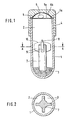
- the mixing container according to the invention contains a first container part 1 which delimits the mixing chamber 2. This contains a generally powdery substance 3 (eg silver powder).
- the first container part 1 is closed by a second removable, cap-shaped container part 4, the inner end wall 4a of which is curved.
- a foil cushion 5 is placed in this container part on an aluminum foil coated with thermoplastic.
- a flowable substance 6 eg mercury
- the film cushion 5 is delimited by the separating films 5a and 5b, which are welded to one another at the edges in a manner known per se in a liquid-tight manner. The edges are clamped between the first and the second container part.
- the film 5b clings to the inner end wall 4a of the second loading part 4 h prior to.
- the film 5a is the destructible separating film facing the pestle 7, which can also be provided with a predetermined breaking point (not shown, not shown).
- the pestle 7 is generally cylindrical and has a tip 8 on the side facing the separating film 5a, by means of which the separating film 5a is pierced when the mixing container is moved intensively in an oscillating mixing device. Furthermore, the pestle has the radial guide ribs 9 in the end region facing the separating film 5a, so that the pestle can be moved in a targeted manner during the mixing process without it jamming.
- the end face of the pestle is curved at the top of the ribs at 10 corresponding to the curvature of the end wall 4a of the second container part 4, so that the apex surfaces of the ribs 9 press the separating film 5a against the separating film 5b when the pestle hits the film cushion 5, so that there is practically no space left between these foils.
- the mixing process which lasts only a few seconds, the second container part 4 with the pressed-out foil cushion 5 is removed, whereupon the pestle 7 and then the ready-to-use amalgam are removed from the mixing chamber 2.
Landscapes
- Health & Medical Sciences (AREA)
- General Health & Medical Sciences (AREA)
- Dentistry (AREA)
- Epidemiology (AREA)
- Life Sciences & Earth Sciences (AREA)
- Animal Behavior & Ethology (AREA)
- Oral & Maxillofacial Surgery (AREA)
- Public Health (AREA)
- Veterinary Medicine (AREA)
- Package Specialized In Special Use (AREA)
- Medical Preparation Storing Or Oral Administration Devices (AREA)
- Packages (AREA)
- Containers And Packaging Bodies Having A Special Means To Remove Contents (AREA)
- Dental Tools And Instruments Or Auxiliary Dental Instruments (AREA)
Priority Applications (1)
| Application Number | Priority Date | Filing Date | Title |
|---|---|---|---|
| AT83107117T ATE22223T1 (de) | 1982-07-22 | 1983-07-21 | Mischbehaelter. |
Applications Claiming Priority (2)
| Application Number | Priority Date | Filing Date | Title |
|---|---|---|---|
| DE3227432 | 1982-07-22 | ||
| DE3227432A DE3227432C1 (de) | 1982-07-22 | 1982-07-22 | Mischbehaelter |
Publications (2)
| Publication Number | Publication Date |
|---|---|
| EP0100937A1 true EP0100937A1 (fr) | 1984-02-22 |
| EP0100937B1 EP0100937B1 (fr) | 1986-09-17 |
Family
ID=6169072
Family Applications (1)
| Application Number | Title | Priority Date | Filing Date |
|---|---|---|---|
| EP83107117A Expired EP0100937B1 (fr) | 1982-07-22 | 1983-07-21 | Récipient mélangeur |
Country Status (6)
| Country | Link |
|---|---|
| US (1) | US4542823A (fr) |
| EP (1) | EP0100937B1 (fr) |
| AT (1) | ATE22223T1 (fr) |
| AU (1) | AU546941B2 (fr) |
| CA (1) | CA1233790A (fr) |
| DE (2) | DE3227432C1 (fr) |
Cited By (1)
| Publication number | Priority date | Publication date | Assignee | Title |
|---|---|---|---|---|
| EP1106147A1 (fr) * | 1999-12-09 | 2001-06-13 | Ivoclar Vivadent AG | Dispositif de mélange |
Families Citing this family (9)
| Publication number | Priority date | Publication date | Assignee | Title |
|---|---|---|---|---|
| US4641974A (en) * | 1985-03-22 | 1987-02-10 | Church John E | Aerosol can agitator |
| US4966465A (en) * | 1988-11-02 | 1990-10-30 | Minnesota Mining And Manufacturing Company | Method for storing, mixing and dispensing dental materials |
| US5236262A (en) * | 1992-07-21 | 1993-08-17 | Creco Corporation | Agitator for a spray can |
| DE4409610C3 (de) * | 1994-03-21 | 2001-09-20 | Scandimed Internat Ab Sjoebo | Mischvorrichtung |
| US20040026270A1 (en) * | 2002-08-07 | 2004-02-12 | Shou-Long Liang | Solution bottle capable of isolating reactant from solution |
| DE102007023399A1 (de) * | 2007-05-22 | 2008-11-27 | Robert Bosch Gmbh | Kapsel zur Aufnahme eines Mediums sowie Verfahren zur Herstellung einer derartigen Kapsel |
| US20090188886A1 (en) * | 2008-01-25 | 2009-07-30 | Florian Troesch | Liquid container system |
| DE102015212394A1 (de) * | 2015-07-02 | 2017-01-05 | Voco Gmbh | Lager- und Mischvorrichtung zur Herstellung eines Dentalpräparats, sowie Verwendung und Verfahren zu deren Herstellung |
| DE112018005864B4 (de) | 2017-11-17 | 2024-03-14 | Schell Dental Ceramics Inc. | Vorrichtung und verfahren zur herstellung von zahnprothesen |
Citations (5)
| Publication number | Priority date | Publication date | Assignee | Title |
|---|---|---|---|---|
| FR1056507A (fr) * | 1952-05-14 | 1954-03-01 | Procédé de distribution des produits nécessaires à la préparation des amalgamesdentaires et dispositifs permettant de réaliser ledit procédé | |
| DE1287251B (de) * | 1964-09-02 | 1969-01-16 | Dentaire Ivoclar Ets | Mehrkammeriger Behaelter fuer die Aufnahme von miteinander reagierenden Substanzen fuer die Herstellung von gebrauchsfertigen Dentalpraeparaten |
| DE1566222A1 (de) * | 1966-11-02 | 1972-02-24 | Goupil Jean Jacques | Vorrichtung zum Aufbewahren und Mischen zweier abgewogener Ausgangssubstanzen zur Herstellung von Amalgam-Zahnersatz od.dgl. |
| US4182447A (en) * | 1977-07-27 | 1980-01-08 | Ira Kay | Device for storing, transporting and mixing reactive ingredients |
| DE2931262A1 (de) * | 1978-08-02 | 1980-02-28 | Johnson & Johnson | Wegwerfbare dentalkapsel |
Family Cites Families (1)
| Publication number | Priority date | Publication date | Assignee | Title |
|---|---|---|---|---|
| BE519008A (fr) * |
-
1982
- 1982-07-22 DE DE3227432A patent/DE3227432C1/de not_active Expired
-
1983
- 1983-07-21 AT AT83107117T patent/ATE22223T1/de not_active IP Right Cessation
- 1983-07-21 EP EP83107117A patent/EP0100937B1/fr not_active Expired
- 1983-07-21 DE DE8383107117T patent/DE3366289D1/de not_active Expired
- 1983-07-21 CA CA000432938A patent/CA1233790A/fr not_active Expired
- 1983-07-22 AU AU17206/83A patent/AU546941B2/en not_active Ceased
-
1984
- 1984-10-22 US US06/663,289 patent/US4542823A/en not_active Expired - Lifetime
Patent Citations (5)
| Publication number | Priority date | Publication date | Assignee | Title |
|---|---|---|---|---|
| FR1056507A (fr) * | 1952-05-14 | 1954-03-01 | Procédé de distribution des produits nécessaires à la préparation des amalgamesdentaires et dispositifs permettant de réaliser ledit procédé | |
| DE1287251B (de) * | 1964-09-02 | 1969-01-16 | Dentaire Ivoclar Ets | Mehrkammeriger Behaelter fuer die Aufnahme von miteinander reagierenden Substanzen fuer die Herstellung von gebrauchsfertigen Dentalpraeparaten |
| DE1566222A1 (de) * | 1966-11-02 | 1972-02-24 | Goupil Jean Jacques | Vorrichtung zum Aufbewahren und Mischen zweier abgewogener Ausgangssubstanzen zur Herstellung von Amalgam-Zahnersatz od.dgl. |
| US4182447A (en) * | 1977-07-27 | 1980-01-08 | Ira Kay | Device for storing, transporting and mixing reactive ingredients |
| DE2931262A1 (de) * | 1978-08-02 | 1980-02-28 | Johnson & Johnson | Wegwerfbare dentalkapsel |
Cited By (1)
| Publication number | Priority date | Publication date | Assignee | Title |
|---|---|---|---|---|
| EP1106147A1 (fr) * | 1999-12-09 | 2001-06-13 | Ivoclar Vivadent AG | Dispositif de mélange |
Also Published As
| Publication number | Publication date |
|---|---|
| EP0100937B1 (fr) | 1986-09-17 |
| AU546941B2 (en) | 1985-09-26 |
| ATE22223T1 (de) | 1986-10-15 |
| CA1233790A (fr) | 1988-03-08 |
| DE3366289D1 (en) | 1986-10-23 |
| US4542823A (en) | 1985-09-24 |
| AU1720683A (en) | 1984-01-26 |
| DE3227432C1 (de) | 1983-10-27 |
Similar Documents
| Publication | Publication Date | Title |
|---|---|---|
| DE4315920C1 (de) | Mischkapsel für Dentalmassen | |
| EP0361108B1 (fr) | Dispositif destiné au mélange par vibrations d'une capsule à plusieurs constituants, plus spécialement pour l'art dentaire | |
| DE10242984B4 (de) | Vorrichtung zum Herstellen von Gemischen aus zwei Komponenten | |
| EP2404864B1 (fr) | Brise-ampoule | |
| DE2831005C2 (de) | Mehrkomponentenkapsel für Dentalzwecke | |
| EP0695700A1 (fr) | Récipient pour substances pouvant s'écouler, en particulier pâteuses et son procédé de fabrication | |
| DE1766334B2 (de) | Behaelter zum aufbewahren und mischen der einzelbestandteile von stoffgemischen, insbesondere von zahnaerztlichen amalgamen | |
| EP0100937B1 (fr) | Récipient mélangeur | |
| DE1761903A1 (de) | Behaelter | |
| DE102016107911A1 (de) | Lagerungs- und Mischsystem für pastenförmige Ausgangskomponenten mit auspressbarer Innenkartusche | |
| EP3045143B1 (fr) | Capsule de melange destinee a la fabrication d'un materiau dentaire | |
| DE2845107C2 (de) | Verfahren zum Einbringen einer Klebemasse in ein Bohrloch | |
| DE2024331C3 (de) | Mischbehälter für die Aufnahme von miteinander reagierenden Substanzen für die Herstellung von gebrauchsfertigen Dentalpräparaten | |
| EP0263313A1 (fr) | Emballage pour produit à deux composants | |
| DE2931262C2 (fr) | ||
| DE3208786A1 (de) | Zweikammerbehaeltnis mit zerstoerbarer trennwand | |
| EP0043468B1 (fr) | Capsule destinée à la conservation et au mélange par vibration d'au moins deux constituants, utilisée notamment dans l'art dentaire | |
| EP0084078A2 (fr) | Installation pour conserver et mélanger par vibration des constituants d'amalgames à usage dentaire | |
| DE2630787C2 (de) | Misch- und Ausbringröhrchen für zähflüssige Dentalpräparate | |
| DE2858334C2 (fr) | ||
| EP2920082B1 (fr) | Récipient pour la distribution d'une matière adhésive sous forme d'un mélange à plusieurs constituants | |
| DE9400374U1 (de) | Mehrkomponentenkapsel, insbesondere für Dentalzwecke | |
| DE1632443C (de) | Mischkapsel | |
| DE2412410A1 (de) | Kartusche zur aufnahme einer zweikomponenten-dichtungsmasse | |
| DE2009403C3 (de) | Mischbehälter fur die Aufnahme von miteinander reagierenden Substanzen zur Herstellung von Gemischen, insbesondere von Dentalpraparaten |
Legal Events
| Date | Code | Title | Description |
|---|---|---|---|
| PUAI | Public reference made under article 153(3) epc to a published international application that has entered the european phase |
Free format text: ORIGINAL CODE: 0009012 |
|
| AK | Designated contracting states |
Designated state(s): AT BE CH DE FR GB IT LI NL SE |
|
| 17P | Request for examination filed |
Effective date: 19840801 |
|
| GRAA | (expected) grant |
Free format text: ORIGINAL CODE: 0009210 |
|
| AK | Designated contracting states |
Kind code of ref document: B1 Designated state(s): AT BE CH DE FR GB IT LI NL SE |
|
| REF | Corresponds to: |
Ref document number: 22223 Country of ref document: AT Date of ref document: 19861015 Kind code of ref document: T |
|
| REF | Corresponds to: |
Ref document number: 3366289 Country of ref document: DE Date of ref document: 19861023 |
|
| ITF | It: translation for a ep patent filed | ||
| ET | Fr: translation filed | ||
| PLBE | No opposition filed within time limit |
Free format text: ORIGINAL CODE: 0009261 |
|
| STAA | Information on the status of an ep patent application or granted ep patent |
Free format text: STATUS: NO OPPOSITION FILED WITHIN TIME LIMIT |
|
| 26N | No opposition filed | ||
| ITTA | It: last paid annual fee | ||
| PGFP | Annual fee paid to national office [announced via postgrant information from national office to epo] |
Ref country code: FR Payment date: 19930528 Year of fee payment: 11 |
|
| PGFP | Annual fee paid to national office [announced via postgrant information from national office to epo] |
Ref country code: SE Payment date: 19930616 Year of fee payment: 11 |
|
| PGFP | Annual fee paid to national office [announced via postgrant information from national office to epo] |
Ref country code: DE Payment date: 19930701 Year of fee payment: 11 |
|
| PGFP | Annual fee paid to national office [announced via postgrant information from national office to epo] |
Ref country code: GB Payment date: 19930712 Year of fee payment: 11 |
|
| PGFP | Annual fee paid to national office [announced via postgrant information from national office to epo] |
Ref country code: BE Payment date: 19930713 Year of fee payment: 11 |
|
| PGFP | Annual fee paid to national office [announced via postgrant information from national office to epo] |
Ref country code: AT Payment date: 19930714 Year of fee payment: 11 |
|
| PGFP | Annual fee paid to national office [announced via postgrant information from national office to epo] |
Ref country code: CH Payment date: 19930721 Year of fee payment: 11 |
|
| PGFP | Annual fee paid to national office [announced via postgrant information from national office to epo] |
Ref country code: NL Payment date: 19930731 Year of fee payment: 11 |
|
| PG25 | Lapsed in a contracting state [announced via postgrant information from national office to epo] |
Ref country code: GB Effective date: 19940721 Ref country code: AT Effective date: 19940721 |
|
| PG25 | Lapsed in a contracting state [announced via postgrant information from national office to epo] |
Ref country code: SE Effective date: 19940722 |
|
| PG25 | Lapsed in a contracting state [announced via postgrant information from national office to epo] |
Ref country code: LI Effective date: 19940731 Ref country code: CH Effective date: 19940731 Ref country code: BE Effective date: 19940731 |
|
| BERE | Be: lapsed |
Owner name: ETABLISSEMENT DENTAIRE IVOCLAR Effective date: 19940731 |
|
| EUG | Se: european patent has lapsed |
Ref document number: 83107117.0 Effective date: 19950210 |
|
| PG25 | Lapsed in a contracting state [announced via postgrant information from national office to epo] |
Ref country code: NL Effective date: 19950201 |
|
| NLV4 | Nl: lapsed or anulled due to non-payment of the annual fee | ||
| GBPC | Gb: european patent ceased through non-payment of renewal fee |
Effective date: 19940721 |
|
| PG25 | Lapsed in a contracting state [announced via postgrant information from national office to epo] |
Ref country code: FR Effective date: 19950331 |
|
| REG | Reference to a national code |
Ref country code: CH Ref legal event code: PL |
|
| PG25 | Lapsed in a contracting state [announced via postgrant information from national office to epo] |
Ref country code: DE Effective date: 19950401 |
|
| EUG | Se: european patent has lapsed |
Ref document number: 83107117.0 |
|
| REG | Reference to a national code |
Ref country code: FR Ref legal event code: ST |