EP0100953A1 - Réacteur à lit fixe pour le traitement, en particulier anaérobie, de boues de curage ou de liquides fortement pollués par des matières organiques - Google Patents
Réacteur à lit fixe pour le traitement, en particulier anaérobie, de boues de curage ou de liquides fortement pollués par des matières organiques Download PDFInfo
- Publication number
- EP0100953A1 EP0100953A1 EP19830107273 EP83107273A EP0100953A1 EP 0100953 A1 EP0100953 A1 EP 0100953A1 EP 19830107273 EP19830107273 EP 19830107273 EP 83107273 A EP83107273 A EP 83107273A EP 0100953 A1 EP0100953 A1 EP 0100953A1
- Authority
- EP
- European Patent Office
- Prior art keywords
- fixed bed
- bed reactor
- reactor according
- nozzle
- treatment
- Prior art date
- Legal status (The legal status is an assumption and is not a legal conclusion. Google has not performed a legal analysis and makes no representation as to the accuracy of the status listed.)
- Granted
Links
Images


Classifications
-
- C—CHEMISTRY; METALLURGY
- C02—TREATMENT OF WATER, WASTE WATER, SEWAGE, OR SLUDGE
- C02F—TREATMENT OF WATER, WASTE WATER, SEWAGE, OR SLUDGE
- C02F3/00—Biological treatment of water, waste water, or sewage
- C02F3/02—Aerobic processes
- C02F3/06—Aerobic processes using submerged filters
-
- B—PERFORMING OPERATIONS; TRANSPORTING
- B05—SPRAYING OR ATOMISING IN GENERAL; APPLYING FLUENT MATERIALS TO SURFACES, IN GENERAL
- B05B—SPRAYING APPARATUS; ATOMISING APPARATUS; NOZZLES
- B05B1/00—Nozzles, spray heads or other outlets, with or without auxiliary devices such as valves, heating means
- B05B1/26—Nozzles, spray heads or other outlets, with or without auxiliary devices such as valves, heating means with means for mechanically breaking-up or deflecting the jet after discharge, e.g. with fixed deflectors; Breaking-up the discharged liquid or other fluent material by impinging jets
- B05B1/262—Nozzles, spray heads or other outlets, with or without auxiliary devices such as valves, heating means with means for mechanically breaking-up or deflecting the jet after discharge, e.g. with fixed deflectors; Breaking-up the discharged liquid or other fluent material by impinging jets with fixed deflectors
- B05B1/265—Nozzles, spray heads or other outlets, with or without auxiliary devices such as valves, heating means with means for mechanically breaking-up or deflecting the jet after discharge, e.g. with fixed deflectors; Breaking-up the discharged liquid or other fluent material by impinging jets with fixed deflectors the liquid or other fluent material being symmetrically deflected about the axis of the nozzle
-
- C—CHEMISTRY; METALLURGY
- C02—TREATMENT OF WATER, WASTE WATER, SEWAGE, OR SLUDGE
- C02F—TREATMENT OF WATER, WASTE WATER, SEWAGE, OR SLUDGE
- C02F3/00—Biological treatment of water, waste water, or sewage
- C02F3/006—Regulation methods for biological treatment
-
- C—CHEMISTRY; METALLURGY
- C02—TREATMENT OF WATER, WASTE WATER, SEWAGE, OR SLUDGE
- C02F—TREATMENT OF WATER, WASTE WATER, SEWAGE, OR SLUDGE
- C02F3/00—Biological treatment of water, waste water, or sewage
- C02F3/02—Aerobic processes
- C02F3/04—Aerobic processes using trickle filters
- C02F3/043—Devices for distributing water over trickle filters
-
- C—CHEMISTRY; METALLURGY
- C02—TREATMENT OF WATER, WASTE WATER, SEWAGE, OR SLUDGE
- C02F—TREATMENT OF WATER, WASTE WATER, SEWAGE, OR SLUDGE
- C02F3/00—Biological treatment of water, waste water, or sewage
- C02F3/28—Anaerobic digestion processes
- C02F3/2806—Anaerobic processes using solid supports for microorganisms
-
- C—CHEMISTRY; METALLURGY
- C02—TREATMENT OF WATER, WASTE WATER, SEWAGE, OR SLUDGE
- C02F—TREATMENT OF WATER, WASTE WATER, SEWAGE, OR SLUDGE
- C02F2209/00—Controlling or monitoring parameters in water treatment
- C02F2209/03—Pressure
-
- Y—GENERAL TAGGING OF NEW TECHNOLOGICAL DEVELOPMENTS; GENERAL TAGGING OF CROSS-SECTIONAL TECHNOLOGIES SPANNING OVER SEVERAL SECTIONS OF THE IPC; TECHNICAL SUBJECTS COVERED BY FORMER USPC CROSS-REFERENCE ART COLLECTIONS [XRACs] AND DIGESTS
- Y02—TECHNOLOGIES OR APPLICATIONS FOR MITIGATION OR ADAPTATION AGAINST CLIMATE CHANGE
- Y02E—REDUCTION OF GREENHOUSE GAS [GHG] EMISSIONS, RELATED TO ENERGY GENERATION, TRANSMISSION OR DISTRIBUTION
- Y02E50/00—Technologies for the production of fuel of non-fossil origin
- Y02E50/30—Fuel from waste, e.g. synthetic alcohol or diesel
-
- Y—GENERAL TAGGING OF NEW TECHNOLOGICAL DEVELOPMENTS; GENERAL TAGGING OF CROSS-SECTIONAL TECHNOLOGIES SPANNING OVER SEVERAL SECTIONS OF THE IPC; TECHNICAL SUBJECTS COVERED BY FORMER USPC CROSS-REFERENCE ART COLLECTIONS [XRACs] AND DIGESTS
- Y02—TECHNOLOGIES OR APPLICATIONS FOR MITIGATION OR ADAPTATION AGAINST CLIMATE CHANGE
- Y02W—CLIMATE CHANGE MITIGATION TECHNOLOGIES RELATED TO WASTEWATER TREATMENT OR WASTE MANAGEMENT
- Y02W10/00—Technologies for wastewater treatment
- Y02W10/10—Biological treatment of water, waste water, or sewage
Definitions
- the invention relates to a fixed bed reactor for treatment, in particular for anaerobic treatment, of sewage sludge or liquids heavily contaminated with organic substances, with a reactor vessel and a fixed bed arranged in the reactor vessel with a multiplicity of practically vertically arranged channels, the walls of which serve as settlement areas for microorganisms.
- a fixed bed reactor is described in US Pat. No. 2,188,162, where, however, only its use for the purification of municipal wastewater by the decomposition of dissolved organic substances by means of aerobic bacteria is described, but not the treatment of sewage sludge. This reference explicitly mentions that the fixed bed is always below the water level.
- DE-AS 24 20 745 When evaluating this reference, it is noted in DE-AS 24 20 745 that the flow velocities in the different tubes are very different. The surfaces of the tubes would not have a sufficiently uniform effect and dead zones could also form. DE-AS 24 20 745 therefore proposes cross-connections between the individual channels. However, this has the disadvantage, that this not only makes the construction of the fixed bed more expensive, but also favors the formation of eddies within the individual channels. However, such vortex formation is not desirable for the use of the fixed bed reactor in an anerobic stage, because it affects the effectiveness of the bacteria. In this regard, reference may be made to the publication by CF Seyfried and M.
- GB-OS 2 069 929 shows an anerobic filter in which wastewater is passed through a distributor over a fixed bed consisting of plastic rings or old aluminum bushings. The liquid then drips down through the fixed bed and is then recirculated again.
- a fixed bed reactor has the disadvantage, however, that it tends to clog rapidly, especially when it is not intended for the naturally heterogeneous sewage sludge in the literature concerned.
- this leads to a reduction in the effective volume and, accordingly, a long treatment time must be provided for safety reasons.
- a distribution device is provided above the fixed bed, which uniformly feeds the individual channels with sewage sludge or liquid, and in that means are provided for determining the level which control the filling level of the reactor in such a way that the individual Channels are not filled to the top.
- a fixed bed reactor clearly defined flow conditions are achieved which counteract a cross-sectional reduction or blockage caused by deposits.
- the walls of the individual channels form large settlement areas for microorganisms, so that the substance contained in the sewage sludge or the liquid is broken down quickly.
- the individual channels are usually easy to monitor during operation, so that if a channel does become blocked, appropriate measures can be taken to expose it quickly.
- An important advantage of the reactor according to the invention is also that the reduction in cross section in one channel cannot have a damaging effect on the remaining part of the reactor. Flow disturbances such as have hitherto occurred in the conventional fixed bed reactors with plastic rings or similar filling material are therefore not to be expected. Since means are provided which determine the filling level of the reactor control that the individual channels are not filled to the top, if one channel becomes blocked, it is filled more than the other channels, so that hydrostatic pressure is generated in this channel, which tends to expose the channel. If this exposure is not carried out automatically during operation, the hydrostatic pressure in the blocked channel can be increased even further by lowering the liquid level in the reactor by pumping.
- the means for determining the level can be formed by a control device with which the level can be kept constant or changed. If the liquid level is lowered, the hydrostatic pressure in the blocked duct is increased further, so that it is exposed in most cases. If it is ensured that the distribution device is in operation when the liquid level is low, a rinsing process takes place in which the walls of the channels are washed. This can also prevent constipation.
- a control device with which the level can be kept constant or changed.
- the respective channel is expediently formed by a tube.
- the tubes advantageously have a polygonal cross section.
- a rectangular cross-section is advantageous because pipes with such a cross-section are commercially available at relatively low prices.
- hexagonal tubes are advantageously chosen. With both square and hexagonal tubes, there are no unused gaps between the tubes.
- the pipes are expediently made of plastic. It can be a relatively cheap plastic, since they are not exposed to any major mechanical stress.
- the tubes can be combined into a bundle that can be lowered into the reactor vessel in one operation. In the case of large reactors, several separate bundles can also be provided. The respective bundle or at least several tubes together can be produced in a single operation, for example by extrusion from plastic.
- the bundle is advantageously reinforced at the top and bottom by a ring made of an L-profile.
- the bundle can also be further reinforced with annular bands at intervals from the upper and lower edges.
- a reinforcement cross connected to the ring is arranged at least at the lower end of the bundle.
- the distribution device is of particular importance for the good functioning of the fixed bed reactor.
- the distribution device has at least one nozzle arranged at the end of the feed line and at least one baffle plate arranged at a distance from this nozzle, which distributes a jet emerging from the nozzle evenly over the upper openings of the channels. Uniform feeding of the channels is important so that practically the same flow rate prevails in all channels.
- the baffle plate also has a central opening, the roof of the reactor vessel being arranged at a predetermined distance from the baffle plate, so that sludge flowing through the central opening hits the inner wall of the roof and thereby predominantly in the central area of the tube bundle is distributed.
- a further baffle plate can also be provided above the baffle plate if the roof is too high.
- An embodiment of the invention provides that the feed line leads through the center of the tube bundle and that the baffle plate is attached to the nozzle by means of rods.
- the nozzle is connected to the supply line with an easily detachable screw connection, e.g. a milk pipe connection.
- This configuration has the advantage that the distribution device and tube bundle form a practical unit that is easily detachable and makes it possible to try out the function of the baffle plate outside of the reactor or with the reactor roof open. Compared to an arrangement of the baffle plate on the reactor roof, this also has the advantage that precise centering of the nozzle and baffle plate is guaranteed from the very beginning.
- the rods advantageously lead conically from the nozzle to the periphery of the baffle plate.
- the distance between the nozzle and at least one of the baffle plates is advantageously adjustable. This makes it possible to regulate the sludge distribution when starting up the reactor or even later.
- a control device for keeping the level constant and / or changing the level is expediently provided.
- This control device can be regarded as part of the distribution device, because in order to enable a good distribution, the level of the liquid in the reactor should be quite a bit be deeper than the top of the channels.
- This control device can be designed such that it lowers the liquid level in the reactor and then increases it again at predetermined time intervals. As mentioned before, this prevents constipation.
- the invention also relates to the use of the fixed bed reactor as a stage in a multi-stage treatment process for sewage sludge or liquids which are highly contaminated with organic substances.
- the fixed bed reactor according to the invention is particularly well suited for this use, since it is largely resistant to clogging.
- the reactor proves to be particularly advantageous as an acidification reactor.
- the construction according to the invention enables a small dimensioning, which even makes it possible to install the acidification reactor in an existing digestion tower, where it only takes up a small fraction of the digestion tower volume.
- the reactor according to the invention can also be used as an acetate and / or methanation reactor.
- its use is not limited to anaerobic processes, but if suitably carried out it can also be used for aerobic processes, such as the so-called "AEROTHERM process", which is described in European patent application No. 81109992.8 "Process for biological heat generation".
- FIGS. 1 to 3 The embodiment of a fixed bed reactor shown in FIGS. 1 to 3 is particularly suitable for the anaerobic treatment of sewage sludge or liquids heavily contaminated with organic substances. It can be used as an acidification reactor, acetate reactor and / or methane reactor.
- the fixed bed reactor essentially consists of a container 11 in which a tube bundle 13 is arranged, the tubes 15 of which are fed with sewage sludge or liquids heavily contaminated with organic substances through a distribution device 17.
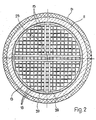
- the tubes 15 form a plurality of channels 18 (FIG. 2) which have a predetermined cross section.
- the walls of these channels 18 serve as settlement areas for microorganisms.
- the tubes 15 and thus also the channels 18 formed by them are arranged practically vertically in the reactor in the exemplary embodiment shown. Above the upper ends of the channels 18 there is the upper space 21 and below the lower ends of the channels 18 the lower space 23.
- the feed line 25 for the sewage sludge leads via the metering pump 24 and the valve 26 to the nozzle 29 of the distribution device 17.
- the discharge line 31 leads from the lower room 23 to the valve 33, to the extraction pump 28 and from there to a further part of the sludge treatment system.
- the valve 35 connects the line 31 via the circulating pump 27 to the Supply line 25. After closing the valves 26 and 33, the contents of the reactor can thus be circulated with the circulation pump 27.
- the gas which may arise during the biochemical reaction can be discharged via the gas outlet 32.
- the tube bundle 13 consists of the tubes 15 with a square cross section.
- These are advantageously plastic pipes with a cross section of more than 30 cm 2 .
- the cross section largely depends on the grain size of the substances contained in the sewage sludge.
- a cross-section of 64 cm 2 proved to be advantageous in the case of conventional sewage sludge.
- round or polygonal tubes could of course also be used.
- square tubes are commercially available at relatively low prices. Hexagonal pipes would be particularly cheap in terms of material consumption, but offer somewhat less settlement area than square pipes.
- the tubes are advantageously made of PVC or polyester and can have a high proportion of waste material and chalk, since they are not exposed to any particular hydraulic and mechanical stresses. This enables a cheap and also relatively light construction and offers no corrosion problems.
- the tube bundle can consist of several parts. As the drawing shows, the tube bundle 13 has a ring 37 and 38 made of an L-profile at the upper and lower edge. As can be seen from Figure 2, the ring 37 is reinforced by a reinforcing cross 39, which is formed from T-profiles. The tube bundle is further reinforced with annular bands 41 for easy assembly at intervals from the upper and lower edges.
- the rings 37, 38, the Reinforcement cross 39 and the bands 41 are expediently made of corrosion-resistant steel or steel with a coating that offers corrosion protection. Otherwise, the tubes 15 carry themselves through the chosen construction.
- the tube bundle 13 has a shape adapted to the reactor vessel 11. In large systems, tube bundle modules are advantageously available, with each module being dimensioned so that it can be easily transported and assembled.
- the distribution device 17 shown in FIGS. 1 and 3 has a nozzle 29 arranged at the end of the feed line 25.
- a baffle plate 40 is arranged at a distance from this nozzle 29, which is advantageously adjustable, which serves to discharge the nozzle 29 Distribute the beam evenly over the upper openings of the channels 18.
- the baffle plate 40 has a central opening 42 which is arranged at a predetermined distance from the roof 43 of the reactor vessel 11. However, it is also possible to provide a further baffle plate 44 above the baffle plate 40, in which case the distance of the baffle plate 40 from the roof 43 is not critical.
- part of the jet emerging from the nozzle 29 is deflected by the baffle plate 40, while another part of the beam passes through the opening 42 and hits the underside of the roof 43 or the baffle plate 44 and from there in particular into the channels 18 of the central area of the tube bundle 13 drips.
- the baffle plate 40 and a possibly provided second baffle plate 44 are carried by rods 45 which run conically from the nozzle 27 to the periphery of the baffle plate 40.
- the distribution device 17 consisting of Baffle plate 40 and possibly 44 and nozzle 29 is detachably fastened to the feed line 25 with a screw connection 47, for example a so-called milk pipe screw connection.
- a screw connection 47 for example a so-called milk pipe screw connection.
- adjustment means can be provided, for example a screw, in order to adjust the distance between the nozzle 29 and the baffle plate 40 and thus enable adjustment during assembly or later in operation.
- 13 hanging eyes 49 are arranged on the tube bundle, which allow the tube bundle 13 e.g. lower it with a crane into the finished container 11 or remove it again for maintenance work.
- the container 11 is expediently provided with a thermal insulation 51 and has an inspection opening 54 provided with a sight glass 53.
- Another opening 56 is located at the lower part of the container and is normally closed by the lid 55.
- a control device 58 is provided which is connected to a sensor 59, e.g. a pressure gauge, is connected and is used to keep constant and / or change the level in the reactor.
- control lines 61, 63 lead to the metering pump 24 and to the withdrawal pump 28. If both pumps 24, 28 have the same delivery volume per unit of time and work at the same time, the level in the reactor basically remains constant.
- the control device 58 can switch a pump 24, 28 on or off.
- the control device 58 can also serve to prevent blockage by lowering the liquid level in the reactor and then increasing it again at predetermined time intervals.
Landscapes
- Life Sciences & Earth Sciences (AREA)
- Microbiology (AREA)
- Water Supply & Treatment (AREA)
- Hydrology & Water Resources (AREA)
- Engineering & Computer Science (AREA)
- Environmental & Geological Engineering (AREA)
- Biodiversity & Conservation Biology (AREA)
- Chemical & Material Sciences (AREA)
- Organic Chemistry (AREA)
- Health & Medical Sciences (AREA)
- Molecular Biology (AREA)
- Biological Treatment Of Waste Water (AREA)
- Apparatus Associated With Microorganisms And Enzymes (AREA)
- Purification Treatments By Anaerobic Or Anaerobic And Aerobic Bacteria Or Animals (AREA)
Priority Applications (1)
| Application Number | Priority Date | Filing Date | Title |
|---|---|---|---|
| AT83107273T ATE17468T1 (de) | 1982-08-06 | 1983-07-25 | Festbettreaktor zur behandlung, insbesondere zur anaeroben behandlung, von klaerschlamm oder mit organischen stoffen stark belasteten fluessigkeiten. |
Applications Claiming Priority (2)
| Application Number | Priority Date | Filing Date | Title |
|---|---|---|---|
| CH4744/82 | 1982-08-06 | ||
| CH474482 | 1982-08-06 |
Publications (2)
| Publication Number | Publication Date |
|---|---|
| EP0100953A1 true EP0100953A1 (fr) | 1984-02-22 |
| EP0100953B1 EP0100953B1 (fr) | 1986-01-15 |
Family
ID=4281758
Family Applications (1)
| Application Number | Title | Priority Date | Filing Date |
|---|---|---|---|
| EP19830107273 Expired EP0100953B1 (fr) | 1982-08-06 | 1983-07-25 | Réacteur à lit fixe pour le traitement, en particulier anaérobie, de boues de curage ou de liquides fortement pollués par des matières organiques |
Country Status (5)
| Country | Link |
|---|---|
| US (1) | US4488960A (fr) |
| EP (1) | EP0100953B1 (fr) |
| AT (1) | ATE17468T1 (fr) |
| BR (1) | BR8304206A (fr) |
| DE (1) | DE3361853D1 (fr) |
Cited By (2)
| Publication number | Priority date | Publication date | Assignee | Title |
|---|---|---|---|---|
| EP0208303A3 (en) * | 1985-07-12 | 1988-06-01 | Linde Aktiengesellschaft | Process and apparatus for the anaerobic biological treatment of organic polluted liquids and/or liquid-solid mixtures |
| EP1849750A1 (fr) * | 2006-04-04 | 2007-10-31 | Technoindustrie S.A. | Installation et procédé de traitement des eaux usées avec un réacteur vertical tubulaire |
Families Citing this family (4)
| Publication number | Priority date | Publication date | Assignee | Title |
|---|---|---|---|---|
| JPS6369590A (ja) * | 1986-09-11 | 1988-03-29 | Iseki Kaihatsu Koki:Kk | 浄化装置 |
| DE4118927A1 (de) * | 1991-06-08 | 1992-12-10 | Mesroc Gmbh | Festbettreaktor zur biologischen behandlung von abwaessern |
| EP1409419A4 (fr) * | 2001-05-31 | 2009-06-24 | Biothane Corp | Appareil de digestion anaerobie, procedes de digestion anaerobie et permettant de minimiser l'utilisation de polymeres inhibiteurs en digestion |
| RU2700490C1 (ru) * | 2018-10-25 | 2019-09-17 | Общество с ограниченной ответственностью "Эволюция Биогазовых Систем" | Биореакторная установка для анаэробной обработки органических отходов животного и растительного происхождения с получением органических удобрений и биогаза |
Citations (6)
| Publication number | Priority date | Publication date | Assignee | Title |
|---|---|---|---|---|
| US1674480A (en) * | 1927-09-10 | 1928-06-19 | A M Lockett & Company Ltd | Spray nozzle |
| US2188162A (en) * | 1938-02-21 | 1940-01-23 | Henry B Schulhoff | Sewage treatment |
| US3189283A (en) * | 1963-01-07 | 1965-06-15 | John R Moore | Spray head |
| FR1590954A (fr) * | 1967-11-08 | 1970-04-20 | ||
| DE2420745A1 (de) * | 1974-04-29 | 1975-10-30 | Ishigaki Mech Ind | Vorrichtung zum klaeren von abwasser |
| GB2068929A (en) * | 1980-02-06 | 1981-08-19 | Celanese Corp | Biological filter and process |
Family Cites Families (7)
| Publication number | Priority date | Publication date | Assignee | Title |
|---|---|---|---|---|
| FR2131092A6 (fr) * | 1971-01-14 | 1972-11-10 | Bergmann Tech | |
| JPS5017049A (fr) * | 1973-06-20 | 1975-02-22 | ||
| US4045344A (en) * | 1974-04-29 | 1977-08-30 | Ishigaki Kiko Co., Ltd. | Apparatus for treating waste water |
| US3966604A (en) * | 1975-03-25 | 1976-06-29 | Diggs Richard E | Apparatus for aerobic decomposition of sewage |
| US4028246A (en) * | 1975-11-20 | 1977-06-07 | Lund Norman S | Liquid purification system |
| US4192746A (en) * | 1978-05-24 | 1980-03-11 | Arvanitakis Kostas S | Liquid clarification system |
| US4246114A (en) * | 1978-11-15 | 1981-01-20 | Multi-Flo, Inc. | Aerobic waste treatment package |
-
1983
- 1983-07-25 EP EP19830107273 patent/EP0100953B1/fr not_active Expired
- 1983-07-25 AT AT83107273T patent/ATE17468T1/de not_active IP Right Cessation
- 1983-07-25 DE DE8383107273T patent/DE3361853D1/de not_active Expired
- 1983-08-02 US US06/519,693 patent/US4488960A/en not_active Expired - Lifetime
- 1983-08-05 BR BR8304206A patent/BR8304206A/pt unknown
Patent Citations (6)
| Publication number | Priority date | Publication date | Assignee | Title |
|---|---|---|---|---|
| US1674480A (en) * | 1927-09-10 | 1928-06-19 | A M Lockett & Company Ltd | Spray nozzle |
| US2188162A (en) * | 1938-02-21 | 1940-01-23 | Henry B Schulhoff | Sewage treatment |
| US3189283A (en) * | 1963-01-07 | 1965-06-15 | John R Moore | Spray head |
| FR1590954A (fr) * | 1967-11-08 | 1970-04-20 | ||
| DE2420745A1 (de) * | 1974-04-29 | 1975-10-30 | Ishigaki Mech Ind | Vorrichtung zum klaeren von abwasser |
| GB2068929A (en) * | 1980-02-06 | 1981-08-19 | Celanese Corp | Biological filter and process |
Cited By (2)
| Publication number | Priority date | Publication date | Assignee | Title |
|---|---|---|---|---|
| EP0208303A3 (en) * | 1985-07-12 | 1988-06-01 | Linde Aktiengesellschaft | Process and apparatus for the anaerobic biological treatment of organic polluted liquids and/or liquid-solid mixtures |
| EP1849750A1 (fr) * | 2006-04-04 | 2007-10-31 | Technoindustrie S.A. | Installation et procédé de traitement des eaux usées avec un réacteur vertical tubulaire |
Also Published As
| Publication number | Publication date |
|---|---|
| BR8304206A (pt) | 1984-03-13 |
| US4488960A (en) | 1984-12-18 |
| EP0100953B1 (fr) | 1986-01-15 |
| DE3361853D1 (en) | 1986-02-27 |
| ATE17468T1 (de) | 1986-02-15 |
Similar Documents
| Publication | Publication Date | Title |
|---|---|---|
| EP0153299B1 (fr) | Procédé et dispositif pour le traitement anaérobie de substrats organiques | |
| EP2041035B1 (fr) | Réacteur doté d'un système de répartition de l'alimentation pour l'épuration anaérobie d'eaux usées | |
| DE69126870T2 (de) | Verfahren und vorrichtung für biologische behandlung | |
| EP0255642A2 (fr) | Réacteur de dispersion liquide-gaz | |
| DE9312978U1 (de) | Vorrichtung zur Entnahme von geklärtem Abwasser aus Rechteckbecken | |
| WO2008099227A1 (fr) | Procédé et dispositif de production de biogaz à partir de biomasse | |
| DE1904206A1 (de) | Anlage zur Abwasserreinigung durch Flockung und Belebung | |
| EP0100953B1 (fr) | Réacteur à lit fixe pour le traitement, en particulier anaérobie, de boues de curage ou de liquides fortement pollués par des matières organiques | |
| DE112020005266T5 (de) | Anaerobe Vergärungsapparatur zur Herstellung von Biogas aus organischen Feststoffen | |
| DE3330696A1 (de) | Anlage zum anaeroben abbau organischer substrate | |
| DE3326879A1 (de) | Biogasreaktor | |
| EP1996318B1 (fr) | Reacteur en boucle dote d'une repartition de gaz anti-colmatage | |
| EP1657222B1 (fr) | Méthode et dispositif de traitement biologique d'une suspension dans un bioréacteur. | |
| DE2420744C3 (de) | Vorrichtung zum Reinigen von Abwasser | |
| EP1493717A1 (fr) | Procédé de lavage d'un réacteur de traitement biologique d'eaux usées | |
| DE202009017869U1 (de) | Vorrichtung zum Trennen von gasförmigen, flüssigen und festen Stoffen in einem Bioreaktor | |
| DE19951194A1 (de) | Mehrzweckschacht, Kleinkläranlage und Abwasserbehandlungsverfahren | |
| DE10155760B4 (de) | Verfahren zur in situ-Entsäuerung schwefelsauren Wassers | |
| DE3324072C2 (de) | Vorrichtung zur anaeroben Abwasserreinigung | |
| EP1588987B1 (fr) | Station d'épuration avec des bassins arrangés d'une manière concentrique | |
| EP0058247A1 (fr) | Procédé et dispositif pour la purification anaérobie de liquides contenant des substances organiques | |
| EP0575294A1 (fr) | Procédé biologique de purification de gaz d'échappement | |
| EP0121729B1 (fr) | Réacteur biologique à déplacement de haut rendement | |
| AT401171B (de) | Vorrichtung zur anaeroben behandlung von organischen substraten | |
| DE10335961B4 (de) | Vorrichtung und Verfahren zur anaeroben Reinigung von Abwasser |
Legal Events
| Date | Code | Title | Description |
|---|---|---|---|
| PUAI | Public reference made under article 153(3) epc to a published international application that has entered the european phase |
Free format text: ORIGINAL CODE: 0009012 |
|
| 17P | Request for examination filed |
Effective date: 19831212 |
|
| AK | Designated contracting states |
Designated state(s): AT BE CH DE FR GB IT LI LU NL SE |
|
| GRAA | (expected) grant |
Free format text: ORIGINAL CODE: 0009210 |
|
| AK | Designated contracting states |
Designated state(s): AT BE CH DE FR GB IT LI LU NL SE |
|
| REF | Corresponds to: |
Ref document number: 17468 Country of ref document: AT Date of ref document: 19860215 Kind code of ref document: T |
|
| ITF | It: translation for a ep patent filed | ||
| REF | Corresponds to: |
Ref document number: 3361853 Country of ref document: DE Date of ref document: 19860227 |
|
| ET | Fr: translation filed | ||
| PLBE | No opposition filed within time limit |
Free format text: ORIGINAL CODE: 0009261 |
|
| STAA | Information on the status of an ep patent application or granted ep patent |
Free format text: STATUS: NO OPPOSITION FILED WITHIN TIME LIMIT |
|
| 26N | No opposition filed | ||
| PGFP | Annual fee paid to national office [announced via postgrant information from national office to epo] |
Ref country code: SE Payment date: 19910702 Year of fee payment: 9 |
|
| PGFP | Annual fee paid to national office [announced via postgrant information from national office to epo] |
Ref country code: LU Payment date: 19910703 Year of fee payment: 9 |
|
| PGFP | Annual fee paid to national office [announced via postgrant information from national office to epo] |
Ref country code: AT Payment date: 19910725 Year of fee payment: 9 |
|
| ITTA | It: last paid annual fee | ||
| PGFP | Annual fee paid to national office [announced via postgrant information from national office to epo] |
Ref country code: NL Payment date: 19910731 Year of fee payment: 9 Ref country code: FR Payment date: 19910731 Year of fee payment: 9 Ref country code: BE Payment date: 19910731 Year of fee payment: 9 |
|
| EPTA | Lu: last paid annual fee | ||
| PGFP | Annual fee paid to national office [announced via postgrant information from national office to epo] |
Ref country code: GB Payment date: 19920706 Year of fee payment: 10 |
|
| PG25 | Lapsed in a contracting state [announced via postgrant information from national office to epo] |
Ref country code: LU Free format text: LAPSE BECAUSE OF NON-PAYMENT OF DUE FEES Effective date: 19920725 Ref country code: AT Effective date: 19920725 |
|
| PG25 | Lapsed in a contracting state [announced via postgrant information from national office to epo] |
Ref country code: SE Effective date: 19920726 |
|
| PG25 | Lapsed in a contracting state [announced via postgrant information from national office to epo] |
Ref country code: BE Effective date: 19920731 |
|
| BERE | Be: lapsed |
Owner name: UTB UMWELTTECHNIK BUCHS A.G. Effective date: 19920731 |
|
| PG25 | Lapsed in a contracting state [announced via postgrant information from national office to epo] |
Ref country code: NL Effective date: 19930201 |
|
| NLV4 | Nl: lapsed or anulled due to non-payment of the annual fee | ||
| PG25 | Lapsed in a contracting state [announced via postgrant information from national office to epo] |
Ref country code: FR Effective date: 19930331 |
|
| REG | Reference to a national code |
Ref country code: FR Ref legal event code: ST |
|
| PG25 | Lapsed in a contracting state [announced via postgrant information from national office to epo] |
Ref country code: GB Effective date: 19930725 |
|
| GBPC | Gb: european patent ceased through non-payment of renewal fee |
Effective date: 19930725 |
|
| EUG | Se: european patent has lapsed |
Ref document number: 83107273.1 Effective date: 19930204 |
|
| PGFP | Annual fee paid to national office [announced via postgrant information from national office to epo] |
Ref country code: CH Payment date: 19970717 Year of fee payment: 15 |
|
| PGFP | Annual fee paid to national office [announced via postgrant information from national office to epo] |
Ref country code: DE Payment date: 19970827 Year of fee payment: 15 |
|
| PG25 | Lapsed in a contracting state [announced via postgrant information from national office to epo] |
Ref country code: LI Free format text: LAPSE BECAUSE OF NON-PAYMENT OF DUE FEES Effective date: 19980731 Ref country code: CH Free format text: LAPSE BECAUSE OF NON-PAYMENT OF DUE FEES Effective date: 19980731 |
|
| REG | Reference to a national code |
Ref country code: CH Ref legal event code: PL |
|
| PG25 | Lapsed in a contracting state [announced via postgrant information from national office to epo] |
Ref country code: DE Free format text: LAPSE BECAUSE OF NON-PAYMENT OF DUE FEES Effective date: 19990501 |