EP0100972B1 - Visionneuse pour lire et/ou afficher des informations enregistrées sur une bande écrite ou imprimée - Google Patents
Visionneuse pour lire et/ou afficher des informations enregistrées sur une bande écrite ou imprimée Download PDFInfo
- Publication number
- EP0100972B1 EP0100972B1 EP83107470A EP83107470A EP0100972B1 EP 0100972 B1 EP0100972 B1 EP 0100972B1 EP 83107470 A EP83107470 A EP 83107470A EP 83107470 A EP83107470 A EP 83107470A EP 0100972 B1 EP0100972 B1 EP 0100972B1
- Authority
- EP
- European Patent Office
- Prior art keywords
- tape
- viewer
- viewer according
- reels
- input
- Prior art date
- Legal status (The legal status is an assumption and is not a legal conclusion. Google has not performed a legal analysis and makes no representation as to the accuracy of the status listed.)
- Expired
Links
Images


Classifications
-
- B—PERFORMING OPERATIONS; TRANSPORTING
- B42—BOOKBINDING; ALBUMS; FILES; SPECIAL PRINTED MATTER
- B42D—BOOKS; BOOK COVERS; LOOSE LEAVES; PRINTED MATTER CHARACTERISED BY IDENTIFICATION OR SECURITY FEATURES; PRINTED MATTER OF SPECIAL FORMAT OR STYLE NOT OTHERWISE PROVIDED FOR; DEVICES FOR USE THEREWITH AND NOT OTHERWISE PROVIDED FOR; MOVABLE-STRIP WRITING OR READING APPARATUS
- B42D19/00—Movable-strip writing or reading apparatus
-
- G—PHYSICS
- G02—OPTICS
- G02B—OPTICAL ELEMENTS, SYSTEMS OR APPARATUS
- G02B25/00—Eyepieces; Magnifying glasses
- G02B25/002—Magnifying glasses
- G02B25/005—Magnifying glasses with means for adjusting the magnifying glass or the object viewed
-
- G—PHYSICS
- G09—EDUCATION; CRYPTOGRAPHY; DISPLAY; ADVERTISING; SEALS
- G09F—DISPLAYING; ADVERTISING; SIGNS; LABELS OR NAME-PLATES; SEALS
- G09F11/00—Indicating arrangements for variable information in which the complete information is permanently attached to a movable support which brings it to the display position
- G09F11/24—Indicating arrangements for variable information in which the complete information is permanently attached to a movable support which brings it to the display position the advertising or display material forming part of a moving band, e.g. in the form of perforations, prints, or transparencies
- G09F11/29—Indicating arrangements for variable information in which the complete information is permanently attached to a movable support which brings it to the display position the advertising or display material forming part of a moving band, e.g. in the form of perforations, prints, or transparencies of a band other than endless
- G09F11/295—Electric control therefor
Definitions
- This invention relates to a viewer for reading and/or displaying information recorded on written or printed tape, according to the preamble of claim 1.
- Another object of the invention is to make the operation of said viewer automatic and adapted to provide for both the unwinding and rewinding of the web tape.
- a further object of this invention is to arrange for said viewer to allow the tape to be unwound stepwise, so that the tape may be read intermittently similarly to the pages of a book.
- An additional object of this invention is to arrange for said viewer to lend itself for use in combination with a magnetic tape recorder, e.g. for utilization as a didactic aid with audiovisual features.
- a not unimportant object of the invention is to provide such a viewer, which is reliable in operation, easy and convenient to operate, and of limited manufacturing cost.
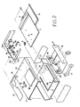
- a viewer 1 comprises a box-like housing 2 which has a bottom portion 3 and cover portion 4.
- the bottom wall 3 is spanned by a U-like slit 5, as well as by an aperture 6.
- a plate or spacer 7 Arranged for fastening to the bottom wall 3, is a plate or spacer 7 having an opening 8, which, in use, will be aligned with the aperture 6 for slidably accommodating a pushbutton 9 therethrough.
- the slit 5 is closed on the inside by the plate 7 and forms a seat for accommodating a U-like suppport 10 having its free ends pivoted to one or more tabs 11 made rigid with the plate 7, e.g. against a bias spring (not shown).
- the box-like body 2 has on one side an opening 12 wherethrough a moving element 13 can be withdrawn drawer-fashion which comprises a bracket with two lateral surfaces 14 and 15 and having two seats 16 for removably accommodating a respective reel or spool 17, which is accordingly supported at its ends.
- a paper web tape can be wound/ unwound which carries the information items or text to be read on the viewer 1.
- Each seat 16, at the side 14 of the bracket, is arranged to engage and disengage, e.g. through a coupling assembly 18, with/from the driveshaft of a respective electric motor M1, M2.
- the electric motors M1, M2 are mounted on a support 19 located close behind the wall of the box-like body 2 which lies opposite the opening 12.
- a catch lever 20 To the support 19, there is pivoted with one end, a catch lever 20 having its other end provided with a detent tooth 21.
- the lever 20 is arranged such as to extend toward the interior of the housing 2 above the button 9 slidable through the openings 6 and 8 until, through an aperture or opening 22 in the wall 14, it engages with a slit 23 formed on the bottom of the bracket or drawer 13.
- the support 19 also includes a lug 25 intended for supporting a light bulb (not shown in Figure 2), as well as mounting brackets 26 for a printed circuit panel 27.
- the cover portion 4 of the box-like body 2 has two holes 28 and 29 therein, for two pushbuttons included in the printed circuit of the underlying panel 27, and a magnifying lens 30 so arranged between the two seats 16 as to be focussed on the tape being unwound from one of the reels 17 and taken up on the other.
- the cover 4 also comprises a slotted and finned area 31 for removing any heat generated within the box-like body 2 by the batteries located in a container 32 and bulb(s) carried on the lug 26.
- a three-way main switch (indicated at 42 in Figure 4 and made accessible from the outside through a hole 33 in . the cover portion 4), namely a switch having an off position, a second position for supplying the electronic drive circuit for the motors M1 and M2, and a third position for supplying, in addition to the electronic circuit, also the bulb(s) 43 carried on the lug 26.
- a suitable electronic drive circuit is illustrated in block form in Figure 3, and more in detail in Figure 4.
- the entire electronic circuitry may be powered with four re-chargeable batteries 40, e.g. 1.5 Volt ones, and/or an external 6 Volt D.C. feeder 41.
- the external feeder not only supplies the viwer circuitry, it can be also arranged so as to recharge the batteries 40.
- the external feeder 41 in turn, can be connected to the electric power supply.
- indicia may be of various types, and in all cases in suitable form for electronic reading, such as in the magnetic or optical forms.
- Said indicia may comprise black "bars" or lines, printed simultaneously with the text along one edge of the tape 44, and constitute information items for the viewer.
- bars are preset to mark the beginning of a passage or "page”, and thus control signals can be supplied to the viewer and the tape 44 be foward and/or reverse fed stepwise through distances which correspond to the pages of a traditional book.
- the flip-flop When the electronic circuit is turned on through the switch 42, the flip-flop assumes its set condition, i.e. with its output Q at a low level, thereby the driver 48 does not control the motor M1. Since the flip-flop 47 is responsive to the rise front of the clock signal CK upon turning off the pushbutton switch 28, its output Q will be switched to a high level, so that the driver 48 is enabled and the motor M1 caused to start.
- the reader 49 is also turned on, and thus the diode 45 will emit light which is directed to impinge on the tape 44 and be reflected therefrom to a phototransistor TR1.
- a phototransistor TR1 Each time that on the tape 44 running under the reader 49, near the text, there appears an indexing mark (black bar), the light from the diode 45 is unre- flected.
- the phototransistor TR1 goes OFF, and through the derivative net 50, supplies a setting pulse to the flip-flop 47, which will stop the motor M1. Since the black bars are provided at the beginning of each page, the tape or "roll book" will be advanced page by page or stepwise.
- the reader 49 it is advantageous to arrange for the reader 49 to be turned off when the motors M1 and M2 are inoperative.
- a respective drive circuit 48 (which comprises the transistors TR2, TR3 and TR4, TR5) for the motors M1 and M2. Therefore if Q is at its high level, the two transistors TR2, TR3 or TR4, TR5 will become conductive and drive either of motors M1, M2.
- either the transistor TR2 or transistor TR4 brings into play the drive circuit of the reader 49, which circuit comprises the transistors TR6 and TR7 and merely constitutes a current generator powering the photodiode 45 only when either of motors M1, M2 is driven.
- the bases of the transistors TR6 and TR7 are brought to a suitable voltage level thanks to the provision of a respective diode, D1 and D2. Diodes D3 and D4 are instead provided on the collectors of the transistors TR3 and TR5 for current to recirculate when the motor is turned off.
- the light emitted by the photodiode 45 is directed onto the tape 44 and received by reflection on the phototransistor TR1.
- the transistor TR9 As the light is reflected (white paper of the tape 44), the transistor TR9 is on and a low level appears at its output.
- the phototransistor TR1 goes OFF; as the transistor TR9 whose output is brought to a high level.
- the transition from the low to the high level of the transistor TR9 is supplied to the input SET of the integrated circuit 47 (pin 6 or pin 8), thereby the integrated circuit is set. Consequently, the output Q (pin 2 and 12) is reverted to the low level and disables the drive circuit 48 of the respective motor M1, M2, which is thus forced to stop.
- a positive pulse is supplied to the drive circuit of the other motor, by utilizing the positive-going transition of the output Q and a resistor-capacitor group 55, 56 or 57, 58.
- the transistor TR8 which is normally OFF, is only brought into play when the running motor is blocked by a reason whatever, that is when the effort applied involves a higher current absorption than a preset threshold value. In this case, the transistor TR8 will set the integrated circuit 47, which in turn will out off the transistor that feeds the motor, thus restoring the whole circuit to the inoperative condition. It will be noted, therefore, that the transistor TR8, along with the resistor 59 and capacitor 60 which are parallel connected between its base and emitter, constitutes a safety device for protecting the motors M1 and M2 and limiting the power supply to the motors.
- the transistors TR10 and TR11 have the function of partly switching off the lamp 43 with either motor running to avoid current absorption peaks which could reflect in an excessive power consumption or adversely affect the proper operation of the feeder.
- the transistors TR10 and TR11 are preceded by a group of diodes D5, D6 and D7, which constitute a logic AND unit, thereby it will be sufficient that either of inputs B or C be at a low level for the base of the transistor TR10 to also be at a low, so that both transistors TR10 and TR11 in the OFF condition. In that case, the lamp 43 is fed with a current whose intensity depends on the value of the resistor 59.
- Figures 5 and 6 show a variation or optional application of the viewer 1 of this invention, that is its coupling to a tape or disk recorder 61 on which a sound has been previously recored which corresponds (e.g. for didactic purposes) to the various "pages" on the tape or book 44 in the viewer.
- an interface unit 62 should be provided which would comprise drive circuitry . simulating the actuation of the recorder push- buttons.
- Such a circuitry is illustrated by the block diagram of Figure 6.
- On the interface 62 there are two pushbutton switches 63 and 64 for respectively controlling the forward and reverse movements of the magnetic tape or disk of the recorder 61.
- On the recorder there are established contacts Rd1 for normal playing forward Rd2 for fast forward, and Rd3 for fast reverse or rewind.
- the contacts Rd1, Rd2 and Rd3 are controlled by respective relays R11, R12 and R13, located in the interface.
- the relay RI1 is driven by a driver unit 65 for fast forward, while the relay RI3 is controlled by a unit 66 controlling the fast reverse or rewind movement.
- the sound signal is picked up over the line S and passed to a processing unit 67 to recognize both the end-of-page information and perform the automatic forward movement, where required, page-by-page, of the tape 44 through the viewer, which is then driven directly by the recorder.
- a processing unit 67 to recognize both the end-of-page information and perform the automatic forward movement, where required, page-by-page, of the tape 44 through the viewer, which is then driven directly by the recorder.
- a suitable signal intended for processing by the interface 67 e.g. in the form of a pulse modulated by a frequency outside the audible range.
- the interface 62 is connected to the viewer 1 through the lines Vd1 and Vd2.
- the viewer 1 operates as follows. It is assumed that the initial condition contemplates both the tape or book 44 within the viewer and the tape or disk within the recorder in their starting positions. For each one page forward step of the viewer, the tape in the recorder is stared automatically, lets the sound be heard and stops, also automatically, at the end of the text relating to that page. The synchronization of the viewer and recorder is maintained by the end-of-page signals recorded in the recorder and processed by the unit 67. Advantageously, such signals may also concern the fast forward movement, as well as the tape rewind movement.
- Figures 7,.8 and 9 shown a variation wherein the interface 62 enables a more sophisticated use of both the viewer 1 and recorder 61, e.g. to produce a powerful didactic aid.
- the book or tape 44 should include, additionally to the printed, written or illustrated text, a whole series of informational indicia, e.g. in the form of black strips or bars (not shown), printed or otherwise appended, for example, along one edge of the tape 44.
- the bars are arranged in accordance with a predetermined code to provide information, for instance on the page numbering, the numbers of the various chapters, the numbers of figures, etc.
- These same information items should also be contained in the tape or disk of the recorder 61 in orderto ensure the video-audio synchronization at any given time.
- FIG. 7 The block diagram of the interface 62 in Figure 8 is shown in Figure 7.
- the diagram of Figure 7 comprises an interface 72 for the viewer and an interface 73 for the recorder.
- the two interfaces 72 and 73 are connected to a microcomputer 74 which can be acceded to through a keyboard 75.
- a digital or alphanumeric display 76 is also connected to the computer 74.
- the interface 70 can read both information on the tape 44 of the viewer and information from the recorder, as well as keep the recorder 61 in step with the viewer 1.
- the display 76 and keyboard 75 enable the terminal to suitably converse with the user. As an example, it will be possible to automatically retrieve a page, chapter, figure, or drawing, etc. previously entered through the keyboard 75. In any case, both the book formed by the tape 44 and the tape or disk in the recorder will stop at the desired position.
- the display 76 it is possible to visually observe the current page, chapter, or any other reference contained in the tape 44.
- all these functions are efficiently performed by the microcomputer 74, which enables the adoptions of variousforms of automation.
- a task or test may be automatically corrected.
- the tape 44 would then contain the text of the task or exercise to be performed, or of the test to be implemented in the form of a questionnaire, and would also include a range of possible answers from which to pick up the one regarded as appropriate by indicating a reference numeral.
- the tape 44 obviously would not contain the correct answer, which is instead contained in the tape or disk of the recorder 61. That answer can only be read by the terminal 70.
- the terminal compares each answer provided by him/her with the correct one, previously recorded, and can thus automatically correct the exercise or test.
- the sound recorder in the recorder 61 may be either the one submitted in copy with a respective tape 44 in the viewer 1, or be modified by the user to insert personal comments to the page he/she is reading.
- the terminal 70 at the discretion of the user, may be converted into a desk calculator, clock or stopwatch.
- each book would include a tape 44 and a memory.
- Said memory should retain the data even in the absence of power supply, and be able to be changed at will by the reader, while always retaining the latest data entered. This is made possible by the utilization, for example, of a memory of the EAROM (Electrically Alterable Read-Only Memory) type.
- EAROM Electrically Alterable Read-Only Memory
- each book or tape 44 will require one or more EAROM memories.
- the EAROM memory would also be supplied to include a standard book reading procedure.
- a few examples of applications for the arrangement of Figure 8 include: underlining of phrases, reading by subjects, reading of codes, and non- sequential reading of the book or text.
- For the underlining of phrases in the book comprised of the tape 44 it will be possible to provde a plurality of light dots 71, for example in the form of light-emitting diodes (LED's) (not shown), which are fastened mechanically to the plate 7 and located laterally with respect to the tape 44.
- LED's light-emitting diodes
- the book may be divided while it is being read into any number of subjects. Further, for each page or even each of the eight spaces into which a page is subdivided, the kind of subject being read may be entered in the EAROM memory. This would apply to any of the various kinds of subjects selected. Ultimately, it will be possible to read the book for just a single subject, as selected by the reader. In that case, the tape 44 would be allowed to run and then stopped at the selected subject, where a luminous dot will indicate the precise location of the desired subject on the page.
- the book contains codes and any particular code is to be retrieved, one can locate that code by entering the number of the code on the keyboard 75. Also in this case, a memory corresponding to the book being used would be required. This embodiment would also allow the entering, during the reading phase, of all the codes which must be marked on each individual page, or those previously marked to be changed, thereby such codes can be retrieved in an automatic manner.
- each page is made to correspond to a suitable code, then it would be possible to subsequently glance over the book according to the numerical order of the codes rather than in a sequential order. This may be useful for example, to a relator who wishes to report on a book, review, or else.
- the book on the tape 44 would only stop, controll- ably, where the relator has previously marked a code and in accordance with an order of progress that the relator him/herself has established.
- the forward/reverse control for the motors M1 and M2 may be provided externally of the viewer 1.
- a connecting unit e.g. a five-pole one, would be provided on the lateral portion of the viewer 1, whereto a remote control would be connected separately.
- the materials and dimensions may vary to suit individual requirements.
Landscapes
- Physics & Mathematics (AREA)
- General Physics & Mathematics (AREA)
- Engineering & Computer Science (AREA)
- Theoretical Computer Science (AREA)
- Optics & Photonics (AREA)
- Management Or Editing Of Information On Record Carriers (AREA)
- Electrically Operated Instructional Devices (AREA)
- Optical Record Carriers And Manufacture Thereof (AREA)
- Displays For Variable Information Using Movable Means (AREA)
- Indexing, Searching, Synchronizing, And The Amount Of Synchronization Travel Of Record Carriers (AREA)
Claims (15)
Priority Applications (1)
| Application Number | Priority Date | Filing Date | Title |
|---|---|---|---|
| AT83107470T ATE30359T1 (de) | 1982-08-06 | 1983-07-29 | Sichtgeraet zum lesen und/oder wiedergeben von auf einem band geschriebenen oder gedruckten informationen. |
Applications Claiming Priority (2)
| Application Number | Priority Date | Filing Date | Title |
|---|---|---|---|
| IT84953/82A IT1159527B (it) | 1982-08-06 | 1982-08-06 | Visore per la lettura e/o visualizzazione di informazioni su nastro scritto o stampato |
| IT8495382 | 1982-08-06 |
Publications (3)
| Publication Number | Publication Date |
|---|---|
| EP0100972A2 EP0100972A2 (fr) | 1984-02-22 |
| EP0100972A3 EP0100972A3 (en) | 1984-11-07 |
| EP0100972B1 true EP0100972B1 (fr) | 1987-10-21 |
Family
ID=11326367
Family Applications (1)
| Application Number | Title | Priority Date | Filing Date |
|---|---|---|---|
| EP83107470A Expired EP0100972B1 (fr) | 1982-08-06 | 1983-07-29 | Visionneuse pour lire et/ou afficher des informations enregistrées sur une bande écrite ou imprimée |
Country Status (6)
| Country | Link |
|---|---|
| US (1) | US4555859A (fr) |
| EP (1) | EP0100972B1 (fr) |
| AT (1) | ATE30359T1 (fr) |
| CA (1) | CA1259832A (fr) |
| DE (1) | DE3374151D1 (fr) |
| IT (1) | IT1159527B (fr) |
Families Citing this family (9)
| Publication number | Priority date | Publication date | Assignee | Title |
|---|---|---|---|---|
| USD290267S (en) | 1984-09-06 | 1987-06-09 | Jones Jerry W | Automatic telephone directory |
| DE3634900A1 (de) * | 1986-10-14 | 1988-04-21 | Andre Kulbach | Werbetrommel |
| US4994987A (en) * | 1987-11-20 | 1991-02-19 | Minnesota Mining And Manufacturing Company | Image access system providing easier access to images |
| US4855725A (en) | 1987-11-24 | 1989-08-08 | Fernandez Emilio A | Microprocessor based simulated book |
| ES2133396T3 (es) * | 1993-05-18 | 1999-09-16 | Man Hee Yoon | Sistema de audio con funcion de ejercicio de lenguaje. |
| US5944574A (en) * | 1996-07-17 | 1999-08-31 | Shoot The Moon Products, Inc. | Interactive audio-visual toy |
| US6981964B2 (en) * | 2001-05-22 | 2006-01-03 | Boston Scientific Scimed, Inc. | Draining bodily fluids with a stent |
| US7294060B2 (en) * | 2003-09-03 | 2007-11-13 | Mattel, Inc. | Interactive device |
| US8764328B2 (en) * | 2010-04-14 | 2014-07-01 | Yan Zhang | Printable automatic paper belt-rolling reader (PB reader) |
Family Cites Families (18)
| Publication number | Priority date | Publication date | Assignee | Title |
|---|---|---|---|---|
| US3088996A (en) * | 1956-05-25 | 1963-05-07 | Melvin A Carter | System for automatically displaying illuminated pictures and delivering sound messages coordinated therewith |
| US2993408A (en) * | 1958-05-22 | 1961-07-25 | Kenneth A Cook | Apparatus for synchronizing the operation of a projector with a tape player |
| US3034241A (en) * | 1960-05-24 | 1962-05-15 | Mc Graw Edison Co | Telephone subscribers list finder and selector mechanism therefor |
| US3174241A (en) * | 1962-03-26 | 1965-03-23 | John W Rohan | Portable dictionary on film reading device |
| CH463813A (de) * | 1967-07-19 | 1968-10-15 | Ritter Eduard | Tonbandkassette |
| GB1235675A (en) * | 1967-08-17 | 1971-06-16 | Standard Telephones Cables Ltd | Intermittently actuable rollers-and-band display apparatus |
| US3510973A (en) * | 1968-04-10 | 1970-05-12 | Translucent Display Corp | Illuminated display |
| FR2056716A5 (fr) * | 1970-08-07 | 1971-05-14 | Rotasign Ltd | |
| US3688262A (en) * | 1970-08-27 | 1972-08-29 | Stephen A Liquori | Modular audio-visual control system |
| FR2152012A5 (fr) * | 1971-09-01 | 1973-04-20 | Treu Gian | |
| FR2153513A5 (fr) * | 1971-09-13 | 1973-05-04 | Delplanque Jean | |
| US4089598A (en) * | 1977-01-21 | 1978-05-16 | Marvin Glass & Associates | Phonograph device |
| US4282522A (en) * | 1977-01-21 | 1981-08-04 | The United States Of America As Represented By The Secretary Of The Army | Display/memory/control system for forward observer source data |
| US4110925A (en) * | 1977-03-28 | 1978-09-05 | Minnesota Mining And Manufacturing Company | Automatic scroll sign |
| US4180933A (en) * | 1977-08-05 | 1980-01-01 | Chammah Georges A | Electric dictionary |
| US4176483A (en) * | 1977-11-18 | 1979-12-04 | Bailey Daniel R | Mobile visual signalling device |
| US4406626A (en) * | 1979-07-31 | 1983-09-27 | Anderson Weston A | Electronic teaching aid |
| CA1126020A (fr) * | 1980-08-19 | 1982-06-22 | Istvan Ralbowsky | Appareil de visualisation d'images eclaire |
-
1982
- 1982-08-06 IT IT84953/82A patent/IT1159527B/it active
-
1983
- 1983-07-29 EP EP83107470A patent/EP0100972B1/fr not_active Expired
- 1983-07-29 AT AT83107470T patent/ATE30359T1/de not_active IP Right Cessation
- 1983-07-29 DE DE8383107470T patent/DE3374151D1/de not_active Expired
- 1983-08-01 US US06/518,888 patent/US4555859A/en not_active Expired - Fee Related
- 1983-08-03 CA CA000433772A patent/CA1259832A/fr not_active Expired
Also Published As
| Publication number | Publication date |
|---|---|
| ATE30359T1 (de) | 1987-11-15 |
| CA1259832A (fr) | 1989-09-26 |
| IT8284953A0 (it) | 1982-08-06 |
| IT1159527B (it) | 1987-02-25 |
| DE3374151D1 (en) | 1987-11-26 |
| EP0100972A3 (en) | 1984-11-07 |
| EP0100972A2 (fr) | 1984-02-22 |
| US4555859A (en) | 1985-12-03 |
Similar Documents
| Publication | Publication Date | Title |
|---|---|---|
| US4451911A (en) | Interactive communicating toy figure device | |
| US5944574A (en) | Interactive audio-visual toy | |
| US4586905A (en) | Computer-assisted audio/visual teaching system | |
| JP2609225B2 (ja) | 記録/再生装置 | |
| EP0254517B1 (fr) | Dispositif pour l'enregistrement de programmes pour appareils électroniques | |
| US4555859A (en) | Viewer for reading and/or displaying information recorded on written or printed tape | |
| US5151687A (en) | Apparatus for logging electronic media-taped material | |
| US20050048457A1 (en) | Interactive device | |
| US4980919A (en) | Message card type of language practising set for children | |
| US4410923A (en) | Display apparatus for recording and/or playback device | |
| US3401470A (en) | Educational apparatus | |
| US3774494A (en) | Automated rhythm teaching machine | |
| US3913133A (en) | Method and apparatus for automatic repeated production of information on selected portions of magnetic wire or tape | |
| US4370684A (en) | Tape recorder with automatic tape end stopping and alarm generation | |
| US4417135A (en) | Power saving electronic counter circuit for tape recorder | |
| US3609878A (en) | Teaching machines | |
| EP0637816A1 (fr) | Livre phonique | |
| US4113994A (en) | Dictation recording and transcribing system utilizing selectable dual message record-playback apparatus | |
| US3664603A (en) | Means for converting magnetic tape cassette to audio-visual cassette | |
| US4385228A (en) | Display device for tape recorder with automatic shut off and reset inhibiting | |
| US20030170603A1 (en) | Audio generating assembly for book and the like | |
| GB2186142A (en) | Input activated and resettable timer | |
| US20050048459A1 (en) | Educational toy with actuators and correlated audible and visual output | |
| JPH0542749B2 (fr) | ||
| KR910000087Y1 (ko) | 비데오 테이프 레코오더용 멜로디 선택회로 |
Legal Events
| Date | Code | Title | Description |
|---|---|---|---|
| PUAI | Public reference made under article 153(3) epc to a published international application that has entered the european phase |
Free format text: ORIGINAL CODE: 0009012 |
|
| AK | Designated contracting states |
Designated state(s): AT BE CH DE FR GB LI NL SE |
|
| PUAL | Search report despatched |
Free format text: ORIGINAL CODE: 0009013 |
|
| AK | Designated contracting states |
Designated state(s): AT BE CH DE FR GB LI NL SE |
|
| 17P | Request for examination filed |
Effective date: 19850423 |
|
| 17Q | First examination report despatched |
Effective date: 19860210 |
|
| GRAA | (expected) grant |
Free format text: ORIGINAL CODE: 0009210 |
|
| AK | Designated contracting states |
Kind code of ref document: B1 Designated state(s): AT BE CH DE FR GB LI NL SE |
|
| PG25 | Lapsed in a contracting state [announced via postgrant information from national office to epo] |
Ref country code: AT Effective date: 19871021 |
|
| REF | Corresponds to: |
Ref document number: 30359 Country of ref document: AT Date of ref document: 19871115 Kind code of ref document: T |
|
| PG25 | Lapsed in a contracting state [announced via postgrant information from national office to epo] |
Ref country code: SE Effective date: 19871031 |
|
| ET | Fr: translation filed | ||
| REF | Corresponds to: |
Ref document number: 3374151 Country of ref document: DE Date of ref document: 19871126 |
|
| PLBE | No opposition filed within time limit |
Free format text: ORIGINAL CODE: 0009261 |
|
| STAA | Information on the status of an ep patent application or granted ep patent |
Free format text: STATUS: NO OPPOSITION FILED WITHIN TIME LIMIT |
|
| 26N | No opposition filed | ||
| PGFP | Annual fee paid to national office [announced via postgrant information from national office to epo] |
Ref country code: CH Payment date: 19950119 Year of fee payment: 12 |
|
| PGFP | Annual fee paid to national office [announced via postgrant information from national office to epo] |
Ref country code: BE Payment date: 19950125 Year of fee payment: 12 |
|
| PGFP | Annual fee paid to national office [announced via postgrant information from national office to epo] |
Ref country code: FR Payment date: 19950127 Year of fee payment: 12 |
|
| PG25 | Lapsed in a contracting state [announced via postgrant information from national office to epo] |
Ref country code: LI Effective date: 19950731 Ref country code: CH Effective date: 19950731 Ref country code: BE Effective date: 19950731 |
|
| PGFP | Annual fee paid to national office [announced via postgrant information from national office to epo] |
Ref country code: GB Payment date: 19951227 Year of fee payment: 13 |
|
| PGFP | Annual fee paid to national office [announced via postgrant information from national office to epo] |
Ref country code: NL Payment date: 19951230 Year of fee payment: 13 |
|
| BERE | Be: lapsed |
Owner name: CORSO FAUSTO Effective date: 19950731 |
|
| REG | Reference to a national code |
Ref country code: CH Ref legal event code: PL |
|
| PG25 | Lapsed in a contracting state [announced via postgrant information from national office to epo] |
Ref country code: FR Effective date: 19960430 |
|
| REG | Reference to a national code |
Ref country code: FR Ref legal event code: ST |
|
| REG | Reference to a national code |
Ref country code: FR Ref legal event code: ST |
|
| REG | Reference to a national code |
Ref country code: FR Ref legal event code: ST |
|
| PG25 | Lapsed in a contracting state [announced via postgrant information from national office to epo] |
Ref country code: GB Effective date: 19960729 |
|
| PGFP | Annual fee paid to national office [announced via postgrant information from national office to epo] |
Ref country code: DE Payment date: 19970124 Year of fee payment: 14 |
|
| PG25 | Lapsed in a contracting state [announced via postgrant information from national office to epo] |
Ref country code: NL Effective date: 19970201 |
|
| GBPC | Gb: european patent ceased through non-payment of renewal fee |
Effective date: 19960729 |
|
| NLV4 | Nl: lapsed or anulled due to non-payment of the annual fee |
Effective date: 19970201 |
|
| PG25 | Lapsed in a contracting state [announced via postgrant information from national office to epo] |
Ref country code: DE Free format text: LAPSE BECAUSE OF NON-PAYMENT OF DUE FEES Effective date: 19980401 |