EP0101013A2 - Lampe fluorescente compacte à culot unique - Google Patents
Lampe fluorescente compacte à culot unique Download PDFInfo
- Publication number
- EP0101013A2 EP0101013A2 EP83107651A EP83107651A EP0101013A2 EP 0101013 A2 EP0101013 A2 EP 0101013A2 EP 83107651 A EP83107651 A EP 83107651A EP 83107651 A EP83107651 A EP 83107651A EP 0101013 A2 EP0101013 A2 EP 0101013A2
- Authority
- EP
- European Patent Office
- Prior art keywords
- ballast
- mounting body
- fluorescent lamp
- compact fluorescent
- base
- Prior art date
- Legal status (The legal status is an assumption and is not a legal conclusion. Google has not performed a legal analysis and makes no representation as to the accuracy of the status listed.)
- Withdrawn
Links
Images

Classifications
-
- H—ELECTRICITY
- H01—ELECTRIC ELEMENTS
- H01J—ELECTRIC DISCHARGE TUBES OR DISCHARGE LAMPS
- H01J61/00—Gas-discharge or vapour-discharge lamps
- H01J61/70—Lamps with low-pressure unconstricted discharge having a cold pressure < 400 Torr
- H01J61/72—Lamps with low-pressure unconstricted discharge having a cold pressure < 400 Torr having a main light-emitting filling of easily vaporisable metal vapour, e.g. mercury
-
- H—ELECTRICITY
- H01—ELECTRIC ELEMENTS
- H01J—ELECTRIC DISCHARGE TUBES OR DISCHARGE LAMPS
- H01J61/00—Gas-discharge or vapour-discharge lamps
- H01J61/02—Details
- H01J61/56—One or more circuit elements structurally associated with the lamp
-
- Y—GENERAL TAGGING OF NEW TECHNOLOGICAL DEVELOPMENTS; GENERAL TAGGING OF CROSS-SECTIONAL TECHNOLOGIES SPANNING OVER SEVERAL SECTIONS OF THE IPC; TECHNICAL SUBJECTS COVERED BY FORMER USPC CROSS-REFERENCE ART COLLECTIONS [XRACs] AND DIGESTS
- Y02—TECHNOLOGIES OR APPLICATIONS FOR MITIGATION OR ADAPTATION AGAINST CLIMATE CHANGE
- Y02B—CLIMATE CHANGE MITIGATION TECHNOLOGIES RELATED TO BUILDINGS, e.g. HOUSING, HOUSE APPLIANCES OR RELATED END-USER APPLICATIONS
- Y02B20/00—Energy efficient lighting technologies, e.g. halogen lamps or gas discharge lamps
Definitions
- the invention relates to a compact fluorescent lamp with a base on one side, consisting of a mounting body which serves as a holder for one or more U-shaped discharge vessels and for a ballast having an essentially rectangular cross section, a base part with a different diameter and a base holding a translucent protective hood for connection to an AC supply voltage.
- the aim is to accommodate a relatively long discharge path in the smallest possible space.
- the ballast and ignition device is usually integrated into the fluorescent lamp.
- DE-OS 21 19 472 several U-shaped discharge vessels are embedded in a holding device together with an AI cup containing the operating circuit and projecting into the lamp space.
- the translucent or diffusing cover is screwed to the holding device.
- the ballast and the igniter are accommodated in accordance with the solution shown in DE-OS 28 35 183 in a lower part arranged below a U-shaped discharge vessel and designed as a housing, details of the type of fastening not being disclosed.
- ballast is arranged within a basic structure.
- the ballast is arranged axially as a long, insulated body in the central part of the lamp.
- the base part and the protective cover are provided with ventilation openings and are held together and secured, for example, by means of friction. Similar information can be found in EP publication 26 428 A3.
- a mounting plate serves as a holding element for a double-curved U-lamp and a ballast.
- the spherical hood is attached to a dome-shaped base part by means of screws.
- a double U-shaped discharge vessel is held together with the ballast and the glow starter within a glass outer bulb by a metal mounting plate.
- the mounting plate encompasses the outer bulb with a rim that stands up on its circumference.
- a plastic lamp base clamps the raised edge of the mounting plate.
- the lamp base and outer bulb do not have any ventilation openings, which means that special measures for heat dissipation on the ballast and on the glow starter are required.
- the object of the invention is to provide a construction for a compact fluorescent lamp with low power, which enables quick and easy installation and in which there is good heat dissipation of the heat developed by the ballast.
- the compact fluorescent lamp with the features mentioned in the preamble of the main claim is according to the invention characterized in that the ballast is arranged with its longitudinal axis at right angles to the longitudinal axis of the lamp and is mounted between the respective mounting body and mounting member and bottom part and is clamped by placing and fixing the base on the mounting body and that the mounting body on the two parallel to the longitudinal axis of the ballast extending side surfaces has further mounting elements for fastening the discharge vessel or vessels. While the holding elements for the ballast on the mounting body are designed in the manner of tabs and at least partially overlap the ballast from above, the holding elements of the base part are designed like struts and support the ballast from below.
- the bottom part also has at its lower end a hollow cylindrical extension with a smaller diameter, which surrounds a cylindrical section of the mounting body located above the extension receiving the base and against which the base rests in a force-fitting manner.
- the holding elements provided for the discharge vessel or vessels on the assembly body are wing-like and engage on the longitudinal sides thereof between the straight legs of the U-shaped discharge vessel or vessels.
- the hood is attached in a simple manner by snapping it onto a hollow cylindrical extension with a larger diameter at the upper end of the base part.
- the mounting body, the bottom part and the hood are advantageously made of plastic, ventilation openings in the bottom part and in the translucent hood ensuring natural convection cooling.
- the inventive construction of the mounting body and the corresponding bottom part enables a Simple and therefore inexpensive installation of the compact fluorescent lamp. All individual parts used are only put together; no welded, riveted or - with the exception of the base which may have to be screwed onto the mounting body - screw connections are required.
- the ballast is held solely on the basis of the tabs or struts formed on the mounting body and on the base part and clamped by means of the attached and fixed base.
- the longitudinal axis of the ballast which is arranged at right angles with respect to the lamp longitudinal axis, has the advantage over similar constructions that the discharge vessel or vessels are shaded less and thus more light is emitted to the outside.
- the translucent protective hood is snapped into the corresponding recesses in the base part by simply snapping it in and at the same time secured against rotation.
- the installation of ventilation openings in the base part and in the protective hood enables forced ventilation of the heat developed by the inductive ballast by convection.
- the use of plastic components reduces the thermal capacity of the entire unit.
- the mounting of the ballast between two plastic components has the advantage that the mains frequency is not transmitted to the entire compact fluorescent lamp via the ballast.
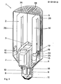
- the single-ended compact fluorescent lamp 1 shown in FIGS. 1 to 3 consists of a mounting body 3 holding two discharge vessels 2, a conical base part 4, a cylindrical protective hood 5 or a spherical protective hood 6 and an inductive ballast 7.
- the ones for the ignition of the electrically discharge vessels 2 connected in series, required glow ignitors 8 with associated interference suppression capacitors 9 are arranged in the threaded section 10 of the mounting body 3.
- a screw base 11 is attached for direct connection of the compact fluorescent lamp 1 to a supply voltage.
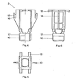
- the mounting body 3 in Figures 4, 5 and 6 is made of plastic and has tabs on the upper side like holding elements 12 which partially enclose the ballast 7 arranged transversely to the lamp longitudinal axis at its upper longitudinal edges.
- the mounting body 3 is further provided on two opposite side surfaces each with a wing-like holding element 13 which is arranged between the straight legs 14 of each discharge vessel 2.
- a leaf spring 15 lies in a recess 16 of each wing-like holding element 13 and on the straight legs 14 of the corresponding discharge vessel 2 in a force-fitting manner, as a result of which this is secured in position.
- a cylindrical section 17 is provided above the threaded section 10 of the mounting body 3.
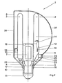
- a lower hollow cylindrical shoulder 18 with a smaller diameter and an upper hollow cylindrical shoulder 19 with a larger diameter are molded onto the conical base part 4, which is made of an opaque plastic.
- the diameter of the lower paragraph 18 is adapted to the cylindrical portion 17 of the mounting body 3.
- the upper shoulder 19 is provided at least on part of its inner circumference with locking elements in the form of grooves 21.
- the upper cylindrical shoulder 19 can be of different lengths as required.
- strut-like mounting elements 22 facing the interior are formed, which support the ballast 7 from below.
- the base 11 presses the base part 4 upwards and thus the ballast 7 against the tab-like holding elements 12 of the mounting body 3.
- the ballast 7 is thus between the holding elements 12 of the Mounting body 3 and the holding elements 22 of the bottom part 4 immovably secured position.
- the bottom part 4 is additionally provided with ventilation slots 23 in the conical area.
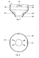
- the unit thus preassembled and wired is finally provided with a protective hood 5 or 6 made of a translucent plastic (FIGS. 1, 2 and 9).
- the protective hood 5 or 6 has in the lower part a rim 25 with a molded-on locking lug 24.
- the diameter of the cylindrical edge 25 is adapted to the diameter of the upper hollow cylindrical shoulder 19 or 20 in the base part 4, the locking lugs 24 snap into the corresponding grooves 21 and produce a simple and firm connection between the base part 4 and the protective hood 5 or 6.
- FIG. 1 Two different forms of protective hoods are shown in FIG.
- a cylindrical protective hood 5 is provided, the upper hollow cylindrical shoulder 19 of the conical base part 4 being designed somewhat longer.
- the protective hood 5 is provided on the outer surface and on the end face with ventilation slots 26 (see also FIG. 9).
- An example with a spherical protective hood 6 is shown on the right.
- the upper hollow cylindrical shoulder 20 of the conical bottom part 4 is designed to be somewhat shorter.
- the spherical protective hood 6 is also provided with ventilation slots 27 on the periphery. Both the cylindrical protective hood 5 and the spherical protective hood 6 have a light-scattering corrugation 28.
- the U-shaped discharge vessels 2 are preferably approximately rectangular in shape in the curved region, which results in the coldest points of the discharge vessels in the outer corners, which are the mercury determine the vapor pressure of the lamp.
- the clear distance between the straight legs 14 of each discharge vessel 2 is advantageously smaller than the discharge vessel diameter.
- the discharge vessels 2 are provided with a three-band phosphor on the inner wall after the shaping process. With an electrical power consumption of 8 W each, the two discharge vessels 2 connected in series have an operating voltage of 55 V each and an operating current of 170 mA.
- each of the two discharge vessels 2 also contains an amalgam-forming substance which regulates the operating steam pressure.
- the ballast 7 is composed of a U / T core, the length of which is approximately 45 mm, the width is approximately 24 mm and the height is approximately 40 mm. With an impedance of approx. 900 ohms, approx. 2.5 W power loss must be taken into account during lamp operation. A glow starter customary for this type of lamp with an interference suppressor connected in parallel is used as the ignition element.
- the compact fluorescent lamp 1 emits a luminous flux of approximately 900 lm.
- the economically usable service life is approx. 5000 h.
- the color temperature for a light color suitable for interior lighting is approx. 2,700 K.
Landscapes
- Non-Portable Lighting Devices Or Systems Thereof (AREA)
- Arrangement Of Elements, Cooling, Sealing, Or The Like Of Lighting Devices (AREA)
Applications Claiming Priority (2)
| Application Number | Priority Date | Filing Date | Title |
|---|---|---|---|
| DE19823230192 DE3230192A1 (de) | 1982-08-13 | 1982-08-13 | Einseitig gesockelte kompakt-leuchstofflampe |
| DE3230192 | 1982-08-13 |
Publications (2)
| Publication Number | Publication Date |
|---|---|
| EP0101013A2 true EP0101013A2 (fr) | 1984-02-22 |
| EP0101013A3 EP0101013A3 (fr) | 1984-11-07 |
Family
ID=6170823
Family Applications (1)
| Application Number | Title | Priority Date | Filing Date |
|---|---|---|---|
| EP83107651A Withdrawn EP0101013A3 (fr) | 1982-08-13 | 1983-08-03 | Lampe fluorescente compacte à culot unique |
Country Status (2)
| Country | Link |
|---|---|
| EP (1) | EP0101013A3 (fr) |
| DE (1) | DE3230192A1 (fr) |
Cited By (2)
| Publication number | Priority date | Publication date | Assignee | Title |
|---|---|---|---|---|
| WO1989011160A1 (fr) * | 1988-05-05 | 1989-11-16 | Coroplan Ag Im Konkurs | Lampe luminescente a gaz a basse pression |
| WO1991010255A1 (fr) * | 1989-12-22 | 1991-07-11 | Gte Products Corporation | Lampe a decharge luminescente negative |
Families Citing this family (1)
| Publication number | Priority date | Publication date | Assignee | Title |
|---|---|---|---|---|
| DE29500786U1 (de) * | 1995-01-19 | 1995-04-06 | Piruzram, Mansur, 95180 Berg | Energiesparlampe |
Family Cites Families (2)
| Publication number | Priority date | Publication date | Assignee | Title |
|---|---|---|---|---|
| US4300073A (en) * | 1979-02-13 | 1981-11-10 | Westinghouse Electric Corp. | Screw-in type lighting unit having a convoluted tridimensional fluorescent lamp |
| NL8001833A (nl) * | 1980-03-28 | 1981-10-16 | Philips Nv | Lagedrukkwikdampontladingslamp. |
-
1982
- 1982-08-13 DE DE19823230192 patent/DE3230192A1/de not_active Withdrawn
-
1983
- 1983-08-03 EP EP83107651A patent/EP0101013A3/fr not_active Withdrawn
Cited By (2)
| Publication number | Priority date | Publication date | Assignee | Title |
|---|---|---|---|---|
| WO1989011160A1 (fr) * | 1988-05-05 | 1989-11-16 | Coroplan Ag Im Konkurs | Lampe luminescente a gaz a basse pression |
| WO1991010255A1 (fr) * | 1989-12-22 | 1991-07-11 | Gte Products Corporation | Lampe a decharge luminescente negative |
Also Published As
| Publication number | Publication date |
|---|---|
| EP0101013A3 (fr) | 1984-11-07 |
| DE3230192A1 (de) | 1984-02-16 |
Similar Documents
| Publication | Publication Date | Title |
|---|---|---|
| DE3005017C2 (fr) | ||
| EP0110054B1 (fr) | Lampe à décharge à haute pression avec culot et douille correspondante | |
| DE3121077C2 (fr) | ||
| EP0173962B1 (fr) | Lampe compacte à décharge à basse pression | |
| DE69826416T2 (de) | Kompakte Leuchtstofflampe, Ballast-Leuchtstofflampe und Leuchtkörper | |
| EP0839381B1 (fr) | Lampe a reflecteur | |
| DE3210005A1 (de) | Kompakte fluoreszenzlampe | |
| EP0452743A1 (fr) | Lampe à décharge compacte à basse pression | |
| DE19963278A1 (de) | Kompaktentladungslampe und Leuchtstofflampe mit Vorschaltgerät | |
| EP0334208B1 (fr) | Lampe compacte à réflecteur | |
| DE3632810C2 (fr) | ||
| EP0580013A1 (fr) | Lampe à décharge haute pression à culotage d'un seul côté | |
| EP0453652B1 (fr) | Lampe à décharge à haute pression | |
| DE1937938B2 (de) | Quecksilberdampfniederdruckentladungslampe mit Haupt- und Nebenamalgam | |
| DE68928593T2 (de) | Metallhalogenidlampenaufbau | |
| EP0237647A1 (fr) | Lampe à décharge pour véhicule | |
| EP0078030B1 (fr) | Lampe électrique | |
| DE69311947T2 (de) | Doppelend Bogenentladungslampe | |
| EP0101013A2 (fr) | Lampe fluorescente compacte à culot unique | |
| DE2118828B2 (de) | Hochdruck-Natriumdampf-Entladungslampe | |
| EP0012234A1 (fr) | Armature à lampe fluorescente | |
| DE69813693T2 (de) | Gesockelte elektrische lampe | |
| EP0150799B1 (fr) | Système d'assemblage pour lampes fluorescentes | |
| EP0118100B1 (fr) | Lampe à décharge à basse pression avec culot à un côté | |
| EP0274107A2 (fr) | Lampe électrique |
Legal Events
| Date | Code | Title | Description |
|---|---|---|---|
| PUAI | Public reference made under article 153(3) epc to a published international application that has entered the european phase |
Free format text: ORIGINAL CODE: 0009012 |
|
| AK | Designated contracting states |
Designated state(s): AT BE CH DE FR GB LI |
|
| PUAL | Search report despatched |
Free format text: ORIGINAL CODE: 0009013 |
|
| AK | Designated contracting states |
Designated state(s): AT BE CH DE FR GB LI |
|
| 17P | Request for examination filed |
Effective date: 19841122 |
|
| STAA | Information on the status of an ep patent application or granted ep patent |
Free format text: STATUS: THE APPLICATION HAS BEEN WITHDRAWN |
|
| 17Q | First examination report despatched |
Effective date: 19860826 |
|
| 18W | Application withdrawn |
Withdrawal date: 19860915 |
|
| RIN1 | Information on inventor provided before grant (corrected) |
Inventor name: WITTMANN, HORST |