EP0101036A2 - Aerosolbehälter - Google Patents
Aerosolbehälter Download PDFInfo
- Publication number
- EP0101036A2 EP0101036A2 EP83107797A EP83107797A EP0101036A2 EP 0101036 A2 EP0101036 A2 EP 0101036A2 EP 83107797 A EP83107797 A EP 83107797A EP 83107797 A EP83107797 A EP 83107797A EP 0101036 A2 EP0101036 A2 EP 0101036A2
- Authority
- EP
- European Patent Office
- Prior art keywords
- metering chamber
- dispensing
- stem
- chamber
- accordance
- Prior art date
- Legal status (The legal status is an assumption and is not a legal conclusion. Google has not performed a legal analysis and makes no representation as to the accuracy of the status listed.)
- Granted
Links
Images
Classifications
-
- B—PERFORMING OPERATIONS; TRANSPORTING
- B65—CONVEYING; PACKING; STORING; HANDLING THIN OR FILAMENTARY MATERIAL
- B65D—CONTAINERS FOR STORAGE OR TRANSPORT OF ARTICLES OR MATERIALS, e.g. BAGS, BARRELS, BOTTLES, BOXES, CANS, CARTONS, CRATES, DRUMS, JARS, TANKS, HOPPERS, FORWARDING CONTAINERS; ACCESSORIES, CLOSURES, OR FITTINGS THEREFOR; PACKAGING ELEMENTS; PACKAGES
- B65D83/00—Containers or packages with special means for dispensing contents
- B65D83/14—Containers for dispensing liquid or semi-liquid contents by internal gaseous pressure, i.e. aerosol containers comprising propellant
- B65D83/44—Valves specially adapted for the discharge of contents; Regulating devices
- B65D83/52—Metering valves; Metering devices
-
- G—PHYSICS
- G01—MEASURING; TESTING
- G01F—MEASURING VOLUME, VOLUME FLOW, MASS FLOW OR LIQUID LEVEL; METERING BY VOLUME
- G01F11/00—Apparatus requiring external operation adapted at each repeated and identical operation to measure and separate a predetermined volume of fluid or fluent solid material from a supply or container, without regard to weight, and to deliver it
- G01F11/28—Apparatus requiring external operation adapted at each repeated and identical operation to measure and separate a predetermined volume of fluid or fluent solid material from a supply or container, without regard to weight, and to deliver it with stationary measuring chambers having constant volume during measurement
- G01F11/30—Apparatus requiring external operation adapted at each repeated and identical operation to measure and separate a predetermined volume of fluid or fluent solid material from a supply or container, without regard to weight, and to deliver it with stationary measuring chambers having constant volume during measurement with supply and discharge valves of the lift or plug-lift type
- G01F11/32—Apparatus requiring external operation adapted at each repeated and identical operation to measure and separate a predetermined volume of fluid or fluent solid material from a supply or container, without regard to weight, and to deliver it with stationary measuring chambers having constant volume during measurement with supply and discharge valves of the lift or plug-lift type for liquid or semiliquid
Definitions
- This invention relates to an aerosol dispensing apparatus for dispensing metered.amounts of fluid material from a main reservoir defined by a container.
- Conventional dispensing systems for selectively dispensing metered doses generally include a metering chamber which holds a measured amount of active ingredient to be dispensed at a later time. If the dispensing system results in charging the metering chamber upon completion of a dispensing process, the charge will remain in the metering chamber until the next dispensing process. Where the time between dispensing consecutive doses is relatively long, phase separation (partition) will occur, resulting in settling of the active ingredient in a non-uniform fashion inside the metering chamber. This problem occurs whether the active ingredient is in an emulsion or in a suspension. In all cases, even for solutions, an air vapor pocket is present as a result of the conventional pressure process for filling the dispensing apparatus. Some of the air pocket can enter the metering chamber along with a charge, thereby reducing the amount of active agent in the metering chamber.
- Conventional dispensing systems include a spring- biased stem positioned in a metering chamber for providing a conduit through which a dose is dispensed. This is often disadvantageous when the spring is inside the metering chamber, because the active agent is likely to adhere to the spring and adversely affect the quantity of active agent that is actually dispensed. This has a deleterious effect upon the functioning of dispensing apparatus for delivering consistently uniform doses of material.
- the active agent may migrate between dispensing operation. If this occurs, the amount of active agent present in the chamber will be non-uniform from one dispensing operation to another; this helps to explain the dose to dose variability experienced with existing dispensers.
- an object of the present invention to provide a new and improved metered aerosol dispenser and method of using such dispenser which overcome all of the above-stated disadvantages of conventional drug dispensers, and which provide a simpler construction and mode of operation than known dispensers.
- an aerosol dispensing apparatus as defined above which includes a metering chamber having a pair of apertures that respectively connect the metering chamber to the main reservoir and to the exterior of the metering chamber, a chamber sealing sleeve mounted within each of the apertures, an additional sealing sleeve mounted within the metering chamber, all of the sleeves being in substantial alignment and a slidable stem having a dispensing passage and a bypass passage, and positioned within and cooperable with the sleeves so that the bypass passage is adapted to selectively fluidically interconnect the main reservoir with the metering chamber and the dispensing passage is adapted to selectively fluidically interconnect the metering chamber with the exterior of the chamber.
- the sleeves selectively cooperate with the two passages as the stem is slidably moved through the metering chamber and the reservoir.
- each unit dose dispensed will comprise an essentially uniform composition. This enables a user to periodically dispense uniform doses of active agents.
- the present device can also dispense metered amounts of drugs or other active agents with increased precision, even with a relatively small metering chamber.
- a relatively small metering chamber By providing a relatively small metering chamber, relatively low volumes of propellant are required.
- propellant e.g., Freon
- the temperature of each dose will not be undesirably cold, and will reduce the discomfort felt by a user when using conventional dispensing apparatus, which inherently use relatively large amounts of cold propellant. This is particularly beneficial in nasal usage, although it is also advantageous in transdermal and oral drug administration.
- Such selectively cooperable structure isolates the metering chamber from the main reservoir at all times except when the apparatus is in its refill, i.e., charging, position; this prevents any flow of active agent between the main reservoir into the metering chamber except during the period in which the metering chamber is charged with a predetermined amount of drug and propellant.
- the propellant is then quickly and easily dispensed from the apparatus in a precisely-metered amount by releasing pressure on the stem, so that the helical spring positioned between the stem flange and the outer surface apparatus will forcibly slide the stem exteriorly of the container to dispense a predetermined dose from the metering chamber.
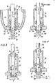
- the apparatus includes container 11, which defines main reservoir 12 for storing pressurized fluid material.
- the fluid material can be, e.g., an emulsion, a solution, or a suspension of an active agent and a propellant.
- the active agent can be any drug administered nasally, transdermally, or orally.
- Specific examples of active agents contemplated for use with this dispensing apparatus include Rocephin, Propanalol, Thymosius, and interferon, which is designed to be suspended in a propellant medium within the container.
- a metering chamber 13 can be positioned within the reservoir, as is Figs. 1-4; alternately, the chamber can be attached exteriorly of the reservoir, as in Fig. 5.
- the metering chamber 13 includes a substantially bell-shaped member 14 which is securely connected to, or integral with, the inner surface of container 11.
- the metering chamber includes a pair of apertures 15 and 17 which respectively connect the metering chamber to the main reservoir and to the exterior of the chamber.
- Chamber sealing sleeves 16 and 18 are mounted within apertures 15 and 17, respectively. That portion of container 11 which is located between inturned flanges 19 of bell-shaped member 14 also comprises a part of the metering chamber.
- Aperture 17 is in substantial alignment with aperture 15 of container 11.
- An additional sealing sleeve 20 is positioned within member 14, between and in alignment with chamber sealing sleeves 16 and 18.
- Sleeve 20 is held within member 14 by spider 21. All of the sealing sleeves are generally annular, in alignment, and are adapted to slidably receive stem 22.
- the stem is generally cylindrical, and includes an outer portion located exteriorly of the container and a generally annular flange 24 positioned adjacent the outer portion.
- Helical spring 26 ⁇ is positioned around the stem between the underside of flange 24 and the outer surface of container 11; the spring serves to bias the stem exteriorly of the container; this biasing force is in addition to the outward pressure exerted on the stem by virtue of the pressurized contents.
- the stem can be depressed inwardly of the reservoir and metering chamber; its movement is limited by stop 23.
- the stem also includes dispensing conduit 28, which is adapted to fluidically interconnect metering chamber 13 with the exterior of the container, and bypass conduit 32, which is adapted to fluidically interconnect the metering chamber and main reservoir 12.
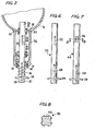
- Fig. 7 illustrates an alternate construction for the slidable stem.
- Stem 40 includes dispensing conduit 28, identical to the dispensing conduit of stem 22. Instead of bypass conduit 32, however, stem 40 has a bypass passage consisting of a plurality of notches 42. Although four notches are shown, as is clear from the cross-sectional view of Fig. 8, any desired number of notches (one or more) can be provided. Each notch has a length greater than the width of one chamber sealing sleeve, so that it will be capable of fluidicall y interconnecting the main reservoir with the metering chamber, similar to the way in which bypass conduit 32 functions.
- Dispensing conduit 28 includes inlet port 29 and nozzle 30.
- the nozzle remains on the exterior of the container during the entire operation of the device.
- Inlet port 29 is selectively cooperable with chamber sealing sleeve 16 and additional sealing sleeve 20, and can be positioned within metering chamber 13, as will be described in greater detail hereinafter.
- bypass conduit 32 includes inlet port 33 'and outlet port 34. The outlet port is positioned within metering chamber 13 throughout the operation of the dispensing apparatus.
- Inlet port 33 is selectively positionable within metering chamber 13, within reservoir 12, and is selectively cooperable with sealing sleeve 18 during operation of the apparatus.
- inlet port 33 (Fig. 6) or the ends of notches 42 located farthest from flange 24 (Fig. 7) are located within the chamber sealing sleeve at the junction of the main reservoir and metering chamber, or are located in member 14, the bypass passages are considered to be within the metering chamber.
- metering chamber 13 By slidably moving the stem through the sealing sleeves, metering chamber 13 can be selectively placed into fluidic communication with either the reservoir or the exterior of the container, or can be isolated from both the reservoir and the exterior.
- the method of using the apparatus begins with the apparatus in a first rest position. In this position, the metering chamber is fluidically isolated from both the exterior of the apparatus and from the main reservoir.... As best shown in Fig. 1, stem 22 is biased outwardly by helical spring 26. In this first position, dispensing conduit inlet aperture 29 is sealingly engaged and surrounded by chamber sealing sleeve 16. This prevents fluidic communication between metering chamber 13 and the exterior of the chamber. In this rest position, the metering chamber is empty, and by virtue of the positioning of bypass conduit 32 within the metering chamber, there is no fluidic communication between the empty metering chamber and filled main reservoir 12. The metering chamber is thus fluidically isolated from both the exterior of the apparatus and from the main reservoir.
- the contents of reservoir 12 Prior to dispensing a metered amount of fluid material from the container, the contents of reservoir 12 are mixed, e.g., by shaking, to disperse the active agent uniformly in the propellant.
- Fig. 2 illustrates the apparatus in its second, empty position.
- the stem is depressed into reservoir 12 and chamber 13 against the biasing force exerted by helical spring 26.
- Fig. 2 illustrates the apparatus in its second, empty position.
- the stem is depressed into reservoir 12 and chamber 13 against the biasing force exerted by helical spring 26.
- the empty position fluidic communication between empty metering chamber 13 and the exterior of the apparatus is established by movement of the stem, which positions dispensing inlet port 29 within metering chamber 13. Because the inlet port is no longer sealed by chamber sealing sleeve 16, the dispensing conduit provides fluidic communication between the chamber and the exterior of the apparatus.
- the metering chamber is still isolated from the main reservoir; bypass conduit inlet port 33 is sealingly engaged by sealing sleeve 18. Accordingly, in the empty position, metering chamber 13 remains isolated from the main reservoir, and void of any fluid material to be dispensed.
- metering chamber 13 is placed into fluidic communication with main reservoir 12 via bypass conduit 32.
- stem flange 24 is in substantial abutment with stop 23.
- the metering chamber is isolated from the exterior of the chamber by virtue of the sealing engagement of additional sealing sleeve 20 about dispensing conduit inlet port 29. This prevents fluid flow from metering chamber 13 to the exterior of the chamber.
- bypass conduit inlet port 32 is positioned within main reservoir 12.
- FIG. 5 An alternate embodiment of the dispensing apparatus is illustrated in Fig. 5.
- This apparatus basically differs from the apparatus of Figs. 1-4 in that metering chamber 35 is located exteriorly of container 11, rather than inside the container; otherwise, the apparatus generally functions as described above with respect to Figs. 1-4.
- Metering chamber 35 is defined by substantially bell-shaped member 36 and that portion of container 11 located between member flanges 37. Chamber 35 includes apertures 39 and 17, and chamber sealing sleeves 15 and 18 are respectively positioned with these apertures.
- Stop 38 is attached to the exterior of member 36 and is adapted to limit movement of stem 22 by engaging flange 24, as stop 23 functions in Figs. 1-4.
- the substantially bell-shaped members (14 and 36) are shown as being attached to container 11; alternately, these members could be formed integrally with the container.
- the apparatus can thus be successively operated to dispense a plurality of uniform and precise doses of the active agent and propellant.
- the stem can be provided in a conventional manner with a protuberance or abutment to restrict its outward movement. In this way, the possibility of inadvertent removal of the stem from the dispensing system would be avoided.
Landscapes
- Physics & Mathematics (AREA)
- Fluid Mechanics (AREA)
- General Physics & Mathematics (AREA)
- Chemical & Material Sciences (AREA)
- Dispersion Chemistry (AREA)
- Engineering & Computer Science (AREA)
- Mechanical Engineering (AREA)
- Containers And Packaging Bodies Having A Special Means To Remove Contents (AREA)
- Nozzles (AREA)
- Agricultural Chemicals And Associated Chemicals (AREA)
Priority Applications (1)
| Application Number | Priority Date | Filing Date | Title |
|---|---|---|---|
| AT83107797T ATE29861T1 (de) | 1982-08-09 | 1983-08-08 | Aerosolbehaelter. |
Applications Claiming Priority (2)
| Application Number | Priority Date | Filing Date | Title |
|---|---|---|---|
| US06/406,421 US4506803A (en) | 1982-08-09 | 1982-08-09 | Metered aerosol dispenser and method of using the dispenser |
| US406421 | 1982-08-09 |
Publications (3)
| Publication Number | Publication Date |
|---|---|
| EP0101036A2 true EP0101036A2 (de) | 1984-02-22 |
| EP0101036A3 EP0101036A3 (en) | 1985-05-22 |
| EP0101036B1 EP0101036B1 (de) | 1987-09-23 |
Family
ID=23607912
Family Applications (1)
| Application Number | Title | Priority Date | Filing Date |
|---|---|---|---|
| EP83107797A Expired EP0101036B1 (de) | 1982-08-09 | 1983-08-08 | Aerosolbehälter |
Country Status (5)
| Country | Link |
|---|---|
| US (1) | US4506803A (de) |
| EP (1) | EP0101036B1 (de) |
| JP (1) | JPS5993668A (de) |
| AT (1) | ATE29861T1 (de) |
| DE (1) | DE3373803D1 (de) |
Cited By (4)
| Publication number | Priority date | Publication date | Assignee | Title |
|---|---|---|---|---|
| WO1995011841A1 (en) * | 1992-04-24 | 1995-05-04 | Howard Michael Sullivan | Metering valve for aerosols |
| WO1996032344A1 (en) * | 1995-04-13 | 1996-10-17 | Glaxo Group Limited | Metered-dose aerosol valve |
| EP0803449A1 (de) * | 1996-04-26 | 1997-10-29 | Bespak plc | Dosierventil für Ausgabebehälter |
| GB2554365A (en) * | 2016-09-22 | 2018-04-04 | Aer Beatha Ltd | Canister and valve |
Families Citing this family (15)
| Publication number | Priority date | Publication date | Assignee | Title |
|---|---|---|---|---|
| GB9214819D0 (en) * | 1992-07-13 | 1992-08-26 | Minnesota Mining & Mfg | Valve assemblies |
| US5421492A (en) * | 1993-11-02 | 1995-06-06 | Glaxo Inc. | Metered aerosol dispensing apparatus and method of use thereof |
| GB2311982B (en) * | 1996-04-09 | 2000-03-08 | Bespak Plc | Improvements in or relating to valves for dispensers |
| US5921447A (en) * | 1997-02-13 | 1999-07-13 | Glaxo Wellcome Inc. | Flow-through metered aerosol dispensing apparatus and method of use thereof |
| JPH11301759A (ja) * | 1998-04-21 | 1999-11-02 | Unisia Jecs Corp | ガス噴射弁及びガス注入に用いられる注入治具 |
| US6454140B1 (en) * | 2000-07-28 | 2002-09-24 | 3M Innovative Properties Companies | Metered dose dispensing aerosol valve |
| US7334347B2 (en) * | 2001-10-30 | 2008-02-26 | Weyerhaeuser Company | Process for producing dried, singulated fibers using steam and heated air |
| US6620405B2 (en) * | 2001-11-01 | 2003-09-16 | 3M Innovative Properties Company | Delivery of hydrogel compositions as a fine mist |
| WO2003062093A2 (en) * | 2001-12-31 | 2003-07-31 | 3M Innovative Properties Company | Valve stem for use in a metering valve |
| KR20050045946A (ko) | 2002-06-25 | 2005-05-17 | 애크럭스 디디에스 피티와이 리미티드 | 비정질 약학적 조성물을 이용한 경피전달속도의 제어 |
| US7497214B2 (en) * | 2002-09-16 | 2009-03-03 | 3M Innovative Properties Company | Aerosol dispensers and adaptors therefor |
| FR2850165A1 (fr) * | 2003-01-16 | 2004-07-23 | Valois Sas | Valve doseuse de distribution de produit fluide. |
| FR2854877B1 (fr) * | 2003-05-15 | 2007-04-20 | Valois Sas | Valve doseuse de distribution de produit fluide. |
| FR2968283B1 (fr) * | 2010-12-03 | 2013-01-04 | Valois Sas | Valve de distribution de produit fluide. |
| DE102011005820A1 (de) * | 2011-03-18 | 2012-09-20 | Ing. Erich Pfeiffer Gmbh | Austragvorrichtung |
Family Cites Families (14)
| Publication number | Priority date | Publication date | Assignee | Title |
|---|---|---|---|---|
| BE535408A (de) * | 1954-08-16 | |||
| DE1033147B (de) * | 1955-11-21 | 1958-06-26 | Wilhelm Waldherr | Dosierventil mit Spruehkopf fuer Spruehdosen oder Flaschen |
| US2980301A (en) * | 1958-09-02 | 1961-04-18 | Riker Laboratories Inc | Metering valve for aerosol container |
| GB864392A (en) * | 1958-11-10 | 1961-04-06 | Rexall Drug Company Ltd | Improvements in or relating to dispensing devices for aerosols |
| FR1299724A (fr) * | 1961-06-16 | 1962-07-27 | Anciens Etablissements E Rober | Perfectionnements aux dispositifs distributeurs de doses de produits déterminées volumétriquement |
| US3176890A (en) * | 1961-08-14 | 1965-04-06 | Potapenko Gennady | Pressurized dispenser with integral container seal |
| US3176887A (en) * | 1961-08-14 | 1965-04-06 | Potapenko Gennady | Pressurized dispenser |
| US3174659A (en) * | 1962-06-29 | 1965-03-23 | Schering Corp | Material dispensing package |
| US3278093A (en) * | 1964-01-13 | 1966-10-11 | Valve Corp Of America | Metering and non-metering aerosol actuator button |
| US3269615A (en) * | 1964-05-27 | 1966-08-30 | Jr Royal T Ferry | Aerosol container with metering valve |
| GB1201918A (en) * | 1966-12-21 | 1970-08-12 | Bespak Industries Ltd | Improvements in or relating to valves for pressurised dispensers |
| US3511418A (en) * | 1968-07-29 | 1970-05-12 | Risdon Mfg Co | Variable capacity aerosol metering valve |
| US3605738A (en) * | 1969-06-20 | 1971-09-20 | Paul J Ciranna | Medicinal spray device |
| GB1336379A (en) * | 1971-05-19 | 1973-11-07 | Neotechnic Eng Ltd | Valve assemblies for pressurised aerosol-dispensing containers |
-
1982
- 1982-08-09 US US06/406,421 patent/US4506803A/en not_active Expired - Fee Related
-
1983
- 1983-08-08 EP EP83107797A patent/EP0101036B1/de not_active Expired
- 1983-08-08 DE DE8383107797T patent/DE3373803D1/de not_active Expired
- 1983-08-08 AT AT83107797T patent/ATE29861T1/de not_active IP Right Cessation
- 1983-08-08 JP JP58144861A patent/JPS5993668A/ja active Pending
Cited By (7)
| Publication number | Priority date | Publication date | Assignee | Title |
|---|---|---|---|---|
| WO1995011841A1 (en) * | 1992-04-24 | 1995-05-04 | Howard Michael Sullivan | Metering valve for aerosols |
| WO1996032344A1 (en) * | 1995-04-13 | 1996-10-17 | Glaxo Group Limited | Metered-dose aerosol valve |
| US6032836A (en) * | 1995-04-13 | 2000-03-07 | Glaxo Group Limited | Metered dose aerosol valve |
| US6482390B1 (en) | 1995-04-13 | 2002-11-19 | Smithkline Beecham Corporation | Aerosol formulations and method |
| EP0803449A1 (de) * | 1996-04-26 | 1997-10-29 | Bespak plc | Dosierventil für Ausgabebehälter |
| GB2554365A (en) * | 2016-09-22 | 2018-04-04 | Aer Beatha Ltd | Canister and valve |
| GB2554365B (en) * | 2016-09-22 | 2022-05-04 | Aer Beatha Ltd | Canister and valve |
Also Published As
| Publication number | Publication date |
|---|---|
| EP0101036B1 (de) | 1987-09-23 |
| ATE29861T1 (de) | 1987-10-15 |
| US4506803A (en) | 1985-03-26 |
| EP0101036A3 (en) | 1985-05-22 |
| DE3373803D1 (en) | 1987-10-29 |
| JPS5993668A (ja) | 1984-05-30 |
Similar Documents
| Publication | Publication Date | Title |
|---|---|---|
| EP0101036B1 (de) | Aerosolbehälter | |
| JP2612865B2 (ja) | 弁 | |
| EP2134616B1 (de) | Abgabevorrichtung mit doppelpumpensystem | |
| RU2630719C2 (ru) | Система для дозирования мягких лекарственных форм | |
| EP0226339B1 (de) | Dosierungsvorrichtung | |
| US8499968B2 (en) | System and method for liquid measuring dispenser | |
| US20080237262A1 (en) | Hanging liquid dispenser | |
| JPH10511573A (ja) | 特定容量用ディスペンサー | |
| JP2001512545A (ja) | エアロゾルのための計量バルブ | |
| JPH11501892A (ja) | エアロゾルバルブ | |
| EP0631558A1 (de) | Ausgabevorrichtung mit zwei kammern | |
| CZ300028B6 (cs) | Zarízení pro dávkování práškového léku inhalací | |
| EP3325172B1 (de) | Spender mit anpassbarer dosierung | |
| JP7422727B2 (ja) | 改善された吸入デバイス | |
| US6193114B1 (en) | Personalized hygienic toothpaste dispenser and toothpaste container holder | |
| JPS59142952A (ja) | 投与量分与装置 | |
| WO1995012533A1 (en) | Metered aerosol dispensing apparatus and method of use thereof | |
| CN106573262A (zh) | 用于配量分配器的放出头和配量分配器 | |
| US7077831B2 (en) | Ophthalmic fluid dispenser | |
| US20220205825A1 (en) | Airless metered fluid dispenser assembly | |
| EP0305441A1 (de) | Aerosolventil | |
| EP3965949B1 (de) | Ein set ausgabebehälter und ein hauptabgabebehälter | |
| GB2236094A (en) | Metering dispenser | |
| JP2004535910A (ja) | 「コンビドーズ」型の流体ディスペンサ装置 |
Legal Events
| Date | Code | Title | Description |
|---|---|---|---|
| PUAI | Public reference made under article 153(3) epc to a published international application that has entered the european phase |
Free format text: ORIGINAL CODE: 0009012 |
|
| 17P | Request for examination filed |
Effective date: 19830808 |
|
| AK | Designated contracting states |
Designated state(s): AT BE CH DE FR GB IT LI NL |
|
| PUAL | Search report despatched |
Free format text: ORIGINAL CODE: 0009013 |
|
| AK | Designated contracting states |
Designated state(s): AT BE CH DE FR GB IT LI NL |
|
| 17Q | First examination report despatched |
Effective date: 19860827 |
|
| GRAA | (expected) grant |
Free format text: ORIGINAL CODE: 0009210 |
|
| AK | Designated contracting states |
Kind code of ref document: B1 Designated state(s): AT BE CH DE FR GB IT LI NL |
|
| REF | Corresponds to: |
Ref document number: 29861 Country of ref document: AT Date of ref document: 19871015 Kind code of ref document: T |
|
| REF | Corresponds to: |
Ref document number: 3373803 Country of ref document: DE Date of ref document: 19871029 |
|
| ITF | It: translation for a ep patent filed | ||
| ET | Fr: translation filed | ||
| PLBE | No opposition filed within time limit |
Free format text: ORIGINAL CODE: 0009261 |
|
| STAA | Information on the status of an ep patent application or granted ep patent |
Free format text: STATUS: NO OPPOSITION FILED WITHIN TIME LIMIT |
|
| 26N | No opposition filed | ||
| PGFP | Annual fee paid to national office [announced via postgrant information from national office to epo] |
Ref country code: BE Payment date: 19890627 Year of fee payment: 7 |
|
| PGFP | Annual fee paid to national office [announced via postgrant information from national office to epo] |
Ref country code: FR Payment date: 19890712 Year of fee payment: 7 |
|
| PGFP | Annual fee paid to national office [announced via postgrant information from national office to epo] |
Ref country code: GB Payment date: 19890731 Year of fee payment: 7 |
|
| PGFP | Annual fee paid to national office [announced via postgrant information from national office to epo] |
Ref country code: DE Payment date: 19890822 Year of fee payment: 7 |
|
| PGFP | Annual fee paid to national office [announced via postgrant information from national office to epo] |
Ref country code: AT Payment date: 19890829 Year of fee payment: 7 |
|
| ITTA | It: last paid annual fee | ||
| PGFP | Annual fee paid to national office [announced via postgrant information from national office to epo] |
Ref country code: NL Payment date: 19890831 Year of fee payment: 7 Ref country code: CH Payment date: 19890831 Year of fee payment: 7 |
|
| ITPR | It: changes in ownership of a european patent |
Owner name: CESSIONE;F. HOFFMANN - LA ROCHE AG |
|
| NLS | Nl: assignments of ep-patents |
Owner name: F. HOFFMANN-LA ROCHE AG TE BAZEL, ZWITSERLAND. |
|
| REG | Reference to a national code |
Ref country code: FR Ref legal event code: TP |
|
| REG | Reference to a national code |
Ref country code: CH Ref legal event code: PUE Owner name: F. HOFFMANN-LA ROCHE AG |
|
| PG25 | Lapsed in a contracting state [announced via postgrant information from national office to epo] |
Ref country code: GB Effective date: 19900808 Ref country code: AT Effective date: 19900808 |
|
| PG25 | Lapsed in a contracting state [announced via postgrant information from national office to epo] |
Ref country code: LI Effective date: 19900831 Ref country code: CH Effective date: 19900831 Ref country code: BE Effective date: 19900831 |
|
| REG | Reference to a national code |
Ref country code: GB Ref legal event code: 732 |
|
| BERE | Be: lapsed |
Owner name: F. HOFFMANN-LA ROCHE A.G. Effective date: 19900831 |
|
| PG25 | Lapsed in a contracting state [announced via postgrant information from national office to epo] |
Ref country code: NL Effective date: 19910301 |
|
| GBPC | Gb: european patent ceased through non-payment of renewal fee | ||
| NLV4 | Nl: lapsed or anulled due to non-payment of the annual fee | ||
| PG25 | Lapsed in a contracting state [announced via postgrant information from national office to epo] |
Ref country code: FR Effective date: 19910430 |
|
| REG | Reference to a national code |
Ref country code: CH Ref legal event code: PL |
|
| PG25 | Lapsed in a contracting state [announced via postgrant information from national office to epo] |
Ref country code: DE Effective date: 19910501 |
|
| REG | Reference to a national code |
Ref country code: FR Ref legal event code: ST |