EP0101095A2 - Méthode et dispositif pour le moulage par injection d'articles avec façonnement simultané de motifs - Google Patents
Méthode et dispositif pour le moulage par injection d'articles avec façonnement simultané de motifs Download PDFInfo
- Publication number
- EP0101095A2 EP0101095A2 EP83108093A EP83108093A EP0101095A2 EP 0101095 A2 EP0101095 A2 EP 0101095A2 EP 83108093 A EP83108093 A EP 83108093A EP 83108093 A EP83108093 A EP 83108093A EP 0101095 A2 EP0101095 A2 EP 0101095A2
- Authority
- EP
- European Patent Office
- Prior art keywords
- pattern
- sheet
- pattern sheet
- female mold
- holding
- Prior art date
- Legal status (The legal status is an assumption and is not a legal conclusion. Google has not performed a legal analysis and makes no representation as to the accuracy of the status listed.)
- Granted
Links
Images


Classifications
-
- B—PERFORMING OPERATIONS; TRANSPORTING
- B29—WORKING OF PLASTICS; WORKING OF SUBSTANCES IN A PLASTIC STATE IN GENERAL
- B29C—SHAPING OR JOINING OF PLASTICS; SHAPING OF MATERIAL IN A PLASTIC STATE, NOT OTHERWISE PROVIDED FOR; AFTER-TREATMENT OF THE SHAPED PRODUCTS, e.g. REPAIRING
- B29C45/00—Injection moulding, i.e. forcing the required volume of moulding material through a nozzle into a closed mould; Apparatus therefor
- B29C45/14—Injection moulding, i.e. forcing the required volume of moulding material through a nozzle into a closed mould; Apparatus therefor incorporating preformed parts or layers, e.g. injection moulding around inserts or for coating articles
-
- B—PERFORMING OPERATIONS; TRANSPORTING
- B29—WORKING OF PLASTICS; WORKING OF SUBSTANCES IN A PLASTIC STATE IN GENERAL
- B29C—SHAPING OR JOINING OF PLASTICS; SHAPING OF MATERIAL IN A PLASTIC STATE, NOT OTHERWISE PROVIDED FOR; AFTER-TREATMENT OF THE SHAPED PRODUCTS, e.g. REPAIRING
- B29C45/00—Injection moulding, i.e. forcing the required volume of moulding material through a nozzle into a closed mould; Apparatus therefor
- B29C45/14—Injection moulding, i.e. forcing the required volume of moulding material through a nozzle into a closed mould; Apparatus therefor incorporating preformed parts or layers, e.g. injection moulding around inserts or for coating articles
- B29C45/1418—Injection moulding, i.e. forcing the required volume of moulding material through a nozzle into a closed mould; Apparatus therefor incorporating preformed parts or layers, e.g. injection moulding around inserts or for coating articles the inserts being deformed or preformed, e.g. by the injection pressure
-
- B—PERFORMING OPERATIONS; TRANSPORTING
- B29—WORKING OF PLASTICS; WORKING OF SUBSTANCES IN A PLASTIC STATE IN GENERAL
- B29C—SHAPING OR JOINING OF PLASTICS; SHAPING OF MATERIAL IN A PLASTIC STATE, NOT OTHERWISE PROVIDED FOR; AFTER-TREATMENT OF THE SHAPED PRODUCTS, e.g. REPAIRING
- B29C45/00—Injection moulding, i.e. forcing the required volume of moulding material through a nozzle into a closed mould; Apparatus therefor
- B29C45/14—Injection moulding, i.e. forcing the required volume of moulding material through a nozzle into a closed mould; Apparatus therefor incorporating preformed parts or layers, e.g. injection moulding around inserts or for coating articles
- B29C45/14008—Inserting articles into the mould
- B29C45/14016—Intermittently feeding endless articles, e.g. transfer films, to the mould
-
- B—PERFORMING OPERATIONS; TRANSPORTING
- B29—WORKING OF PLASTICS; WORKING OF SUBSTANCES IN A PLASTIC STATE IN GENERAL
- B29C—SHAPING OR JOINING OF PLASTICS; SHAPING OF MATERIAL IN A PLASTIC STATE, NOT OTHERWISE PROVIDED FOR; AFTER-TREATMENT OF THE SHAPED PRODUCTS, e.g. REPAIRING
- B29C51/00—Shaping by thermoforming, i.e. shaping sheets or sheet like preforms after heating, e.g. shaping sheets in matched moulds or by deep-drawing; Apparatus therefor
- B29C51/10—Forming by pressure difference, e.g. vacuum
-
- B—PERFORMING OPERATIONS; TRANSPORTING
- B29—WORKING OF PLASTICS; WORKING OF SUBSTANCES IN A PLASTIC STATE IN GENERAL
- B29C—SHAPING OR JOINING OF PLASTICS; SHAPING OF MATERIAL IN A PLASTIC STATE, NOT OTHERWISE PROVIDED FOR; AFTER-TREATMENT OF THE SHAPED PRODUCTS, e.g. REPAIRING
- B29C45/00—Injection moulding, i.e. forcing the required volume of moulding material through a nozzle into a closed mould; Apparatus therefor
- B29C45/14—Injection moulding, i.e. forcing the required volume of moulding material through a nozzle into a closed mould; Apparatus therefor incorporating preformed parts or layers, e.g. injection moulding around inserts or for coating articles
- B29C45/1418—Injection moulding, i.e. forcing the required volume of moulding material through a nozzle into a closed mould; Apparatus therefor incorporating preformed parts or layers, e.g. injection moulding around inserts or for coating articles the inserts being deformed or preformed, e.g. by the injection pressure
- B29C2045/14213—Injection moulding, i.e. forcing the required volume of moulding material through a nozzle into a closed mould; Apparatus therefor incorporating preformed parts or layers, e.g. injection moulding around inserts or for coating articles the inserts being deformed or preformed, e.g. by the injection pressure deforming by gas or fluid pressure in the mould cavity
-
- B—PERFORMING OPERATIONS; TRANSPORTING
- B29—WORKING OF PLASTICS; WORKING OF SUBSTANCES IN A PLASTIC STATE IN GENERAL
- B29C—SHAPING OR JOINING OF PLASTICS; SHAPING OF MATERIAL IN A PLASTIC STATE, NOT OTHERWISE PROVIDED FOR; AFTER-TREATMENT OF THE SHAPED PRODUCTS, e.g. REPAIRING
- B29C45/00—Injection moulding, i.e. forcing the required volume of moulding material through a nozzle into a closed mould; Apparatus therefor
- B29C45/14—Injection moulding, i.e. forcing the required volume of moulding material through a nozzle into a closed mould; Apparatus therefor incorporating preformed parts or layers, e.g. injection moulding around inserts or for coating articles
- B29C45/1418—Injection moulding, i.e. forcing the required volume of moulding material through a nozzle into a closed mould; Apparatus therefor incorporating preformed parts or layers, e.g. injection moulding around inserts or for coating articles the inserts being deformed or preformed, e.g. by the injection pressure
- B29C2045/14286—Injection moulding, i.e. forcing the required volume of moulding material through a nozzle into a closed mould; Apparatus therefor incorporating preformed parts or layers, e.g. injection moulding around inserts or for coating articles the inserts being deformed or preformed, e.g. by the injection pressure means for heating the insert
- B29C2045/14295—Injection moulding, i.e. forcing the required volume of moulding material through a nozzle into a closed mould; Apparatus therefor incorporating preformed parts or layers, e.g. injection moulding around inserts or for coating articles the inserts being deformed or preformed, e.g. by the injection pressure means for heating the insert the heating means being used for feeding the insert into the mould
-
- B—PERFORMING OPERATIONS; TRANSPORTING
- B29—WORKING OF PLASTICS; WORKING OF SUBSTANCES IN A PLASTIC STATE IN GENERAL
- B29C—SHAPING OR JOINING OF PLASTICS; SHAPING OF MATERIAL IN A PLASTIC STATE, NOT OTHERWISE PROVIDED FOR; AFTER-TREATMENT OF THE SHAPED PRODUCTS, e.g. REPAIRING
- B29C45/00—Injection moulding, i.e. forcing the required volume of moulding material through a nozzle into a closed mould; Apparatus therefor
- B29C45/14—Injection moulding, i.e. forcing the required volume of moulding material through a nozzle into a closed mould; Apparatus therefor incorporating preformed parts or layers, e.g. injection moulding around inserts or for coating articles
- B29C45/14827—Injection moulding, i.e. forcing the required volume of moulding material through a nozzle into a closed mould; Apparatus therefor incorporating preformed parts or layers, e.g. injection moulding around inserts or for coating articles using a transfer foil detachable from the insert
Definitions
- the present invention relates to a method and device for molding articles by injection molding while simultaneously imprinting on or transferring onto the molded articles patterns on a continuous sheet.
- a method and device for molding articles by injection molding while simultaneously imprinting or transferring patterns on a continuous sheet on or to the molded articles mean that a sheet bearing patterns is pressed against the cavity surface of a female mold by applying the pressure or by evacuating the cavity of the female mold and a molten plastic compound is injected through a male mold into the cavity defined by the male and female molds which are mated together, whereby the patterns are imprinted or transferred on the surface of molded articles or finished products.
- an injection molding machine with a male mold and a female mold is used.
- An operator inserts a sheet bearing patterns between the male and female molds and the air under pressure is blown out through the male mold so that the sheet may be firmly pressed against the cavity surface of the female mold.
- molten plastic material is injected through the male mold into the cavity defined by the male and female molds which are mated together so that the sheet bearing patterns may be imprinted on the surface of the molded articles and then the finished products are ejected.
- a pattern sheet a pattern bearing sheet
- the pattern sheet must be inserted correctly between the male and female molds so that the pattern sheet may be correctly registered with the surfaces of molded articles. Furthermore, such operation is cumbersome.
- a method for molding an article by injection molding while simultaneously imprinting on or transferring onto the molded article a pattern on a continuous pattern sheet wherein,prior to the injection of molten plastic material, a softened pattern sheet is pre- molded by pressing said pattern sheet under the air pressure against the cavity surface of a female mold, and wherein the molten plastic material is injected .from a male mold into the cavity defined between said male and female molds mated together with each other to integrate the molded article with the pattern on said pattern sheet, said method comprising: (a) disposing said pattern sheet which has a plurality of patterns and register marks spaced apart from each other by a predetermined distance in its longitudinal direction in such a way that said pattern sheet is transported so as to cover the opening.-of said female mold; (b) detecting the register marks on said pattern sheet at the upstream of said female mold so that pattern-sheet-holding-and-transferring means holds said pattern sheet at a predetermined position with respect to each pattern thereon; (c
- FIG. 1 an article or finished product molded in accordance with the present invention.
- a pattern sheet 2 is attached onto the surface of the article 1:...
- pattern 10 is imprinted on the raised portion of the article and characters or letters 12 are imprinted at the lower portion of the pattern sheet 2.
- FIG. 2 is shown in vertical cross section an injection molding machine M in accordance with the present invention. It comprises a male mold 16 securely attached to a stationary plate 20 and a female mold 18 securely mounted on a movable plate 24 which is movable toward or away from the male mold 16 by means of a ram 22. An ejector 26 is disposed adjacent to the movable plate 24 for ejecting a molded article out of the mold by pins (not shown).
- An injection device 28 is extended through the stationary plate 20 and the male mold 16 and is communicated with a nozzle 30 so that a molten plastic material is forced through the injection device 28 and the nozzle 30 into the cavity of the female mold 18.
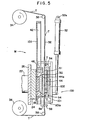
- a pattern sheet 32 is vertically transported between the male and female molds 16 and 18; that is, the pattern sheet 32 is unrolled from a supply roll 34 and is taken by a take-up roll 36.
- the travel of the pattern sheet 32 from the supply roll 34 to the take-up roll 36 is controlled by an upper and a lower guide roll 38.
- the supply roll 36 is biased in the clockwise direction under the force of a spring (not shown) while the take-up roll 36 is biased in the counterclockwise direction under the force of a spring (not shown) in FIG. 2 so that tension is exerted on the pattern sheet 32.
- the pattern sheet 32 has desired patterns which are spaced apart from each other by a suitable distance in the longitudinal direction.
- the pattern sheet 32 is set according to the type of forming patterns on the article. That is, when the sheet 32 is so set that the patterns thereon face the male mold 16, the patterns are formed on the backside of the sheet covering the molded article. On the contrary, when the sheet 32 is so set that the patterns thereon face the female mold 18, the patterns are formed on the front surface of the sheet covering the molded article. When only ink for forming the patterns on the pattern sheet 32 is transferred onto the surface of the molded article, the pattern sheet 32 must be so set that the- patterns thereon face the male mold 16.
- the pattern sheet 32 is provided with register marks T which are spaced apart by a predetermined distance in the longitudinal direction.
- Each register mark T comprises a horizontal line segment a for determining the vertical position (the x-direction) of the sheet 32 and a vertical line segment b for determining the horizontal position (the y-direction) thereof. That is, the register mark T is in the form of +, but it is to be understood that the horizontal line segment a and the vertical line segment b may be marked separately.
- a pattern-sheet-holding-and-transferring device 100 which transfers a pattern on the sheet 32 by the predetermined distance onto the female mold 18 while holding and heating the sheet 32.
- the device 100 has a supporting plate 101 on which a moving plate 102 slidable vertically is mounted via a known shift mechanism including a drive screw and a servomotor (not shown).
- a cover member 44 which can slide in the lateral direction (the direction perpendicular to the direction in which the moving plate 102 can slide on the supporting plate 101) via the same shift mechanism as above.
- the cover member 44 faces a frame member 46 which is movable integrally with the member 44 on a base plate 103 but cannot separate away from the surface of the base plate 103.
- the base plate 103 is provided between two vertical rails 42 which extend vertically on the opposite sides of the female mold 18. Furthermore, the female mold 18 is adapted to project through an opening formed in the base plate 103.
- the supporting plate 101 has a plurality of legs 101a at its four corners, which engage with the rails 42.
- the frame member 46 is disposed in opposed relationship with a cover member 44 which has a heating unit 44a embedded therein.
- the frame member 46 is in the shape of a letter U.
- the cover member 44 is provided with a plurality of air passages 50 which in turn are communicated with a common air passage 51 which in turn is communicated with an air operating means including a vacuum pump, a compressed air source and a.change-over valve (all not shown).
- the heating unit 44a may comprise a heat plate, a sintered metal plate or a high-frequency heating plate.
- the sheet-holding-and-transferring device .100 is vertically moved by means of an air cylinder 52, the upper end of which is pivoted at 52 to a stationary frame (not shown) and the lower end of which is pivoted to the supporting plate 101.
- Detectors such as photosensors 54 are located at the positions above and below the cover member 44 or the frame member 46 and are adapted to detect the register marks T on the pattern sheet 32. It is preferable to provide two detectors 54 for determining the position in the X-direction and two detectors 54 for determining the position in the Y-direction.
- Pressure members 56 are disposed in opposed relationship with each other below the female mold 18 and are adapted to clamp the pattern sheet 32.
- the pressure members 56 are moved toward or away from each other by means of an air cylinder (not shown) mounted on the movable plate 24.
- the pressure members 56 are extended transversely of the pattern sheet 32 and one of the pressure members 56 is held stationary while the other is moved toward or away from the one.
- the female die 18- is provided with air passages 58 which will be described in more detail hereinafter.
- the cover member 44 and the frame member 46 are moved- in unison with each other away from a reference position to detect the register mark T.
- a control circuit (not.shown) stops the operation of the moving mechanism.
- the cover and frame members 44 and 46 are caused to move in the Y-direction by means of another.moving mechanism.
- the control circuit stops the operation thereof.
- the cover plate 44 is displaced to a predetermined position with respect to a pattern on the pattern sheet 32.
- the vacuum pump is operated so that the air is sucked through the air passages 50 and the common air passage 51 of the cover member 44, whereby the pattern sheet 32 is firmly sucked against the heating element 44a.
- the air cylinders 106 is actuated so that the cover member 44 is caused to move toward the frame member 46, whereby the pattern sheet 32 is clamped between the cover and frame members 44 and 46.
- the cylinder 52 is slightly rotated toward the frame member 46 around the axis 52a.
- the two moving mechanisms are operated again so that the cover and frame members 44 and 46 are returned to their reference or initial positions.
- the piston rod of the air cylinder 52 is extended as shown in FIG. 5 to cause the sheet-holding-and-transferring-device 100 to move downward along the rails 42 and are stopped at the predetermined position in opposed relatinship with the female mold. 18.
- the pattern sheet 32 is unrolled and advanced by a predetermined distance (that is, one pitch between the adjacent patterns).
- the pattern sheet 32 is heated and softened by the heating unit 44a during its travel. Since the frame member 46 is in the form of a letter U, it may surround the female mold 18 and the cover plate 44 upon which the pattern sheet 32 is pressed closes the cavity of the female mold 18. In this case, the pattern on the pattern sheet 32 is in predetermined positional relationship with the bottom 18a of the cavity of the female mold 18.
- the air in the cavity of the female die 18 is evacuated through the air passages 58 while the compressed air is blown through the common air passage 51 and the air passages 50 of the cover member 44 by changing the change over valve of the air operating means so that the pattern sheet 32 is forced to be separated from the surface of the heating unit 44a and pressed against the cavity surfaces of the female die 18 as shown in FIG. 6. If the cavity of the female mold 18 is deep, a part of the cover member 44 may be moved toward the cavity of the female mold 18 while holding the pattern sheet 32 so that when the cavity of the female mold 18 is evacuated, the pattern sheet may be pre-molded without being expanded excessively.
- the compressed air is supplied through the common air passage 51 and the air passages 50 so that the pattern sheet 32 is pressed against the surfaces of the cavity of the female mold 18, but it is to be understood that while the compressed air is supplied through the air passages 50 in the manner described above, the air in the cavity of the female mold 18 may be discharged through the air passages 58 without. evacuating operation. In the latter case, the female mold 19 must be provided a relatively large number of air discharge passages 58. However, the openings of such passages 58 are imprinted on the surface of the molded articles or finished products. As a result, such arrangement is not preferable in practice.
- the cavity of the female mold 18 is evacuated as described above, so that it is not needed to provide a plurality of air discharge passages. Accordingly, the trace of the openings of the air passages 58 is almost not left on the surfaces of molded articles or finished products.
- the air cylinder 106 is so actuated that the cover member 44 is moved away from the frame member 46 to release the sheet:32.
- the piston rod of the air cylinder 52 is retracted to cause the device 100 to return to their initial positions as shown in FIG. 2.
- the pressure members 56 clamp the pattern sheet 32 to prevent the pattern sheet 32 from moving upwardly.
- the ram 22 is actuated so that the female mold 18 is moved toward the male mold 16.
- Molten plastic material is injected through the injection device 28 and the nozzle 30 into a cavity 60 defined by the mated male and female molds 16 and 18, whereby molded articles on which the patterns are imprinted can be obtained.
- the operation of the air cylinder 52 and other air cylinders 106 is controlled by a conventional control circuit (not shown).
- the pattern sheet 32 can adhere to the surface of molded articles or finished products, it is punched as shown in FIG. 8, but when only an ink image is transferred to the molded articles or finished products, the pattern sheet 32 is not punched as shown in FIG. 8.
- the cover member 44 in response to the output signals from the detectors, the cover member 44 is moved to a predetermined position with respect to the pattern sheet 32. Then the pattern sheet 32 is sucked against the heating unit 44a of the cover member 44 so that the pattern sheet 32 is held while being heated. Thereafter, the cover member 44 is moved to a predetermined position with respect to the female mold 18 and the cavity of the female mold 18 is evacuated and the compressed air is supplied to the back of the pattern sheet 32 so that the pattern sheet 32 is pressed against the cavity surface 18a of the female mold 18.
- a pattern on the pattern sheet 32 is correctly registered with the cavity surface of the female mold 18,
- the pattern sheet 32 is heated while it is sucked against the heating unit 44a of the cover member 44. Therefore, there is no fear that the pattern sheet 32 is separated from the heating unit 44a of the cover member 44 and the pattern on the pattern sheet -32 is misaligned with respect to the cavity surface of the female mold 18.
- the male and female molds may be so arranged that the thicknesses of the molded articles or finished products may be varied. That is, the cavity of a female mold 71 is deep and the female mold 71 is moved toward or away from a male mold 70.
- An adjusting frame 72 is fitted over the male mold 70 and is connected to the piston rods 74 of cylinders 73 mounted on the stationary plate 20. As a result, when the cylinders 73 are actuated, the frame 72 can be moved toward or away from the female mold 71.
- the leading end of the frame 72 is adapted to engage with the upper periphery of the female mold 71.
- the depth of the cavity 76 of the female mold 71 that is, the thicknesses of the molded articles or finished products can be adjusted.
- the detectors 54 have been described as detecting the X-direction first and then the Y-direction, but it is to be understood that they can simultaneously detect both the X- and Y-directions.
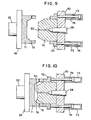
- air passages 75 may be extended through the side wall of the female mold 71 as shown in FIGS. 9 and 10.
Landscapes
- Engineering & Computer Science (AREA)
- Mechanical Engineering (AREA)
- Manufacturing & Machinery (AREA)
- Injection Moulding Of Plastics Or The Like (AREA)
- Moulds For Moulding Plastics Or The Like (AREA)
Applications Claiming Priority (4)
| Application Number | Priority Date | Filing Date | Title |
|---|---|---|---|
| JP14239882A JPS5931130A (ja) | 1982-08-17 | 1982-08-17 | 射出成形同時絵付装置 |
| JP142398/82 | 1982-08-17 | ||
| JP78592/83 | 1983-05-04 | ||
| JP7859283A JPS59202830A (ja) | 1983-05-04 | 1983-05-04 | 絵付用射出成形金型装置 |
Publications (3)
| Publication Number | Publication Date |
|---|---|
| EP0101095A2 true EP0101095A2 (fr) | 1984-02-22 |
| EP0101095A3 EP0101095A3 (en) | 1985-08-14 |
| EP0101095B1 EP0101095B1 (fr) | 1988-11-17 |
Family
ID=26419649
Family Applications (1)
| Application Number | Title | Priority Date | Filing Date |
|---|---|---|---|
| EP83108093A Expired EP0101095B1 (fr) | 1982-08-17 | 1983-08-16 | Méthode et dispositif pour le moulage par injection d'articles avec façonnement simultané de motifs |
Country Status (5)
| Country | Link |
|---|---|
| US (2) | US4545752A (fr) |
| EP (1) | EP0101095B1 (fr) |
| KR (1) | KR880000022B1 (fr) |
| CA (1) | CA1207506A (fr) |
| DE (1) | DE3378462D1 (fr) |
Cited By (15)
| Publication number | Priority date | Publication date | Assignee | Title |
|---|---|---|---|---|
| EP0249363A3 (en) * | 1986-06-11 | 1988-03-09 | Peerless Plastics Packaging Limited | Improvements in the manufacture of moulded plastics articles |
| US4912288A (en) * | 1985-09-04 | 1990-03-27 | Allen-Bradley International Limited | Moulded electric circuit package |
| DE4116437A1 (de) * | 1990-05-25 | 1991-11-28 | Volkswagen Ag | Verfahren zur herstellung eines kunststoff-formteils |
| EP0442128A3 (en) * | 1990-02-10 | 1992-01-15 | Bayer Ag | Method for producing multilayered moulded bodies |
| EP0448249A3 (en) * | 1990-03-19 | 1993-02-24 | Illinois Tool Works Inc. | Method an die for forming a shaped component |
| GB2261187A (en) * | 1991-11-08 | 1993-05-12 | Kaumagraph Flint Corp | Method of making a molded applique product |
| US5220488A (en) * | 1985-09-04 | 1993-06-15 | Ufe Incorporated | Injection molded printed circuits |
| EP0652833A1 (fr) * | 1992-07-31 | 1995-05-17 | Minnesota Mining And Manufacturing Company | Film de peinture et son procede de fabrication |
| WO2004037511A1 (fr) * | 2002-10-25 | 2004-05-06 | G.M.P. Spa | Procede de production d'articles en polyurethanne, et dispositif correspondant |
| WO2005025892A1 (fr) * | 2003-09-18 | 2005-03-24 | Douglas Winston Sell | Procede de formation de surface decorative |
| EP1600273A4 (fr) * | 2003-03-03 | 2009-03-18 | Ykk Corp | Procede et dispositif de transfert par decalcomanie |
| US7794226B2 (en) | 2007-04-05 | 2010-09-14 | Hon Hai Precision Industry Co., Ltd. | Injection molding device |
| WO2021170382A1 (fr) * | 2020-02-28 | 2021-09-02 | Leonhard Kurz Stiftung & Co. Kg | Procédé et dispositif pour décorer une pièce moulée par injection et pièce moulée par injection |
| EP4311650A1 (fr) * | 2022-07-29 | 2024-01-31 | Chuzhou Yujian Travel Product Co., Ltd. | Procédé de moulage par injection, moule d'injection et moule de mise en forme de bagages |
| AT18320U1 (de) * | 2023-09-08 | 2024-10-15 | Engel Austria Gmbh | Heizvorrichtung |
Families Citing this family (81)
| Publication number | Priority date | Publication date | Assignee | Title |
|---|---|---|---|---|
| GB2262063B (en) * | 1991-12-07 | 1996-01-10 | Courtaulds Films & Packaging | Polymeric films |
| US4710116A (en) * | 1985-02-06 | 1987-12-01 | Pierre Dromigny | System for feeding film, forming a partial coating at least of a molded object, into a mold |
| FR2592833B1 (fr) * | 1986-01-13 | 1988-05-27 | Dromigny Pierre | Procede de fabrication d'objets par injection de matiere synthetique sur une pellicule decoupee a partir d'une bande et machine pour la mise en oeuvre du procede |
| US4676938A (en) * | 1986-01-15 | 1987-06-30 | John Brown, Inc. | Differential pressure thermoforming and foam injection process and apparatus |
| NL8602387A (nl) * | 1986-05-30 | 1987-12-16 | Kornelis Kunsthars Prod Ind Bv | Werkwijze voor het vervaardigen van een kunststofdeksel, daarvoor ingerichte matrijs en deksel verkregen met de werkwijze. |
| JPH0528629Y2 (fr) * | 1986-07-23 | 1993-07-22 | ||
| AU600010B2 (en) * | 1986-08-04 | 1990-08-02 | George Ralph Hann | Transfer printing method |
| US4865675A (en) * | 1986-09-25 | 1989-09-12 | Canon Kabushiki Kaisha | Process of and apparatus for hot pressure adhesion treatments |
| YU46540B (sh) | 1987-03-27 | 1993-11-16 | Avery International Corp. | Laminat koji se može toplotno oblikovati za obrazovanje trodimenzionalno oblikovanog spoljneg sloja na spoljnoj površini panela automobila |
| US5707697A (en) * | 1987-03-27 | 1998-01-13 | Avery Dennison Corporation | Dry paint transfer product having high DOI automotive paint coat |
| US6835267B1 (en) * | 1987-03-27 | 2004-12-28 | Avery Dennison Corporation | Dry paint transfer process and product |
| JPS6426420A (en) * | 1987-07-23 | 1989-01-27 | Nissha Printing | Device for injection molding and simultaneous decorating and manufacture of injection-molded and simultaneously decorated product |
| KR960007011B1 (ko) * | 1988-01-29 | 1996-05-27 | 미쓰이세끼유 가가꾸 고오교오 가부시끼가이샤 | 적층성형체 및 그 제조방법 |
| US5000903A (en) * | 1989-04-06 | 1991-03-19 | Libbey-Owens-Ford Co. | Method of molding plastic products having chemically bonded protective coatings |
| US5082435A (en) * | 1989-06-23 | 1992-01-21 | Yoshida Industry Co., Ltd. | Transferring and molding apparatus |
| JP2960080B2 (ja) * | 1989-09-04 | 1999-10-06 | ポリプラスチックス株式会社 | 射出成形品の表面装飾方法 |
| USD331222S (en) | 1990-05-15 | 1992-11-24 | Truck Lite Company, Inc. | Combined socket and connector for automotive lamp assembly |
| US5271882A (en) * | 1990-11-09 | 1993-12-21 | Tokai Kogyo Kabushiki Kaisha | Blow molding process with sheet interposed between mold and product being molded |
| JPH0788019B2 (ja) * | 1991-02-06 | 1995-09-27 | 河西工業株式会社 | 自動車用内装部品の製造方法 |
| JPH04338525A (ja) * | 1991-05-15 | 1992-11-25 | Tokai Kogyo Kk | ブロー成形体及びその製造方法 |
| EP0551526B1 (fr) * | 1991-07-31 | 1996-10-02 | Sumitomo Chemical Company Limited | Procede pour mouler un article multicouche |
| US5604006A (en) * | 1992-01-24 | 1997-02-18 | Cascade Engineering | Label inmolding process and article of manufacture produced therefrom |
| JP2797043B2 (ja) * | 1992-04-06 | 1998-09-17 | 住友重機械工業 株式会社 | 射出成形金型へのラベル供給方法 |
| JP2695348B2 (ja) * | 1992-04-28 | 1997-12-24 | 大日本印刷株式会社 | 射出成形同時絵付装置 |
| US6159402A (en) * | 1992-08-04 | 2000-12-12 | Valyi; Emery I. | Process for forming a color coated article |
| CA2101300C (fr) * | 1992-08-04 | 1998-07-28 | Emery I. Valyi | Methode et appareil pour faconner des articles revetus, de couleur |
| US6174488B1 (en) * | 1992-10-26 | 2001-01-16 | Kasai Kogyo Co., Ltd. | Method for fabricating a laminated molded assembly |
| DE4319751C1 (de) * | 1993-06-15 | 1995-01-12 | Schneider Franz Kunststoffwerk | Verfahren zum Überziehen eines Gegenstandes mit einem Bezug und Vorrichtung zur Durchführung des Verfahrens |
| WO1995003927A1 (fr) * | 1993-08-03 | 1995-02-09 | Aotec, Inc. | Procede et appareil pour fabriquer des miroirs en plastique, et miroirs ainsi obtenus |
| WO1995004642A1 (fr) * | 1993-08-09 | 1995-02-16 | Aotec, Inc. | Moule de fabrication de plastique stratifie |
| US5527173A (en) * | 1994-04-18 | 1996-06-18 | Husky Injection Molding Systems Ltd. | Apparatus for producing plastic articles with inserts |
| DE19515192C2 (de) | 1994-04-25 | 1997-08-21 | Dainippon Printing Co Ltd | Verfahren zum Ausbilden eines Musters auf einem Artikel während dessen Spritzguß und Vorrichtung zu diesem Zweck |
| SE504039C2 (sv) * | 1994-06-14 | 1996-10-21 | Ericsson Telefon Ab L M | Sätt att formspruta plast |
| US5676981A (en) * | 1994-06-21 | 1997-10-14 | Dai Nippon Printing Co., Ltd. | Simultaneous injection molding and patterning apparatus |
| US5843555A (en) * | 1994-12-20 | 1998-12-01 | Dai Nippon Printing Co., Ltd. | Pattern-bearing sheet for use in simultaneous injection-molding and pattern-forming method |
| US5633022A (en) * | 1995-06-08 | 1997-05-27 | Old Line Plastics, Inc. | Differential temperature vacuum-forming tool |
| JP2788023B2 (ja) | 1995-11-29 | 1998-08-20 | 大日本印刷株式会社 | 射出成形同時絵付装置 |
| JP2828242B2 (ja) * | 1995-11-30 | 1998-11-25 | 大日本印刷株式会社 | 射出成形同時絵付装置及び方法 |
| KR100440398B1 (ko) * | 1996-01-31 | 2004-10-26 | 니혼샤신 인사츠 가부시키가이샤 | 그림모양이새겨진성형품제조장치와이의제조방법 |
| JP2954535B2 (ja) * | 1996-07-31 | 1999-09-27 | 大日本印刷株式会社 | 射出成形同時絵付方法及び装置 |
| US5885408A (en) * | 1997-06-02 | 1999-03-23 | Owens-Illinois Closure Inc. | Method and apparatus for delivering labels and the like to a compression molding machine for molding plastic closures |
| JP3439646B2 (ja) | 1998-02-20 | 2003-08-25 | 大日本印刷株式会社 | 射出成形同時絵付装置 |
| US5943957A (en) * | 1998-03-12 | 1999-08-31 | Nibco Inc. | Method and device for in-mold pad printing |
| FR2777497B1 (fr) * | 1998-04-16 | 2000-05-19 | Fenec Sa | Machine pour la fabrication de pieces telles que des patins destines a etre fixes sous les pieds des meubles |
| JPH11309766A (ja) * | 1998-04-30 | 1999-11-09 | Dainippon Printing Co Ltd | 射出成形同時絵付方法及び装置 |
| NL1011331C2 (nl) * | 1999-02-18 | 2000-08-22 | Montan Nederland B V | Opberginrichting met beveiligingsmiddelen. |
| TW580426B (en) * | 1999-06-29 | 2004-03-21 | Four Pillars Entpr Co Ltd | Method for processing a film |
| US6497567B1 (en) * | 1999-10-04 | 2002-12-24 | Serigraph Inc. | Multi-purpose processing apparatus |
| US6478569B1 (en) | 1999-12-10 | 2002-11-12 | Slipmate Company | Hybrid injection molding apparatus for enhancing cosmetic appearance of molded articles |
| US6475423B1 (en) | 1999-12-10 | 2002-11-05 | Slipmate Company | Hybrid injection molding process for enhancing exterior appearance of molded articles by molding fabric thereto |
| IT1311066B1 (it) * | 1999-12-23 | 2002-02-28 | Sacmi | Metodo per decorare la sommita' della capsula di chiusura di unrecipiente. |
| TWI284092B (en) * | 2000-02-01 | 2007-07-21 | Sumitomo Chemical Co | Recycled plastic product |
| US20050258559A1 (en) * | 2000-09-01 | 2005-11-24 | Johansen Loren R | Thermoforming method and apparatus for use in an injection molding machine |
| WO2002020241A1 (fr) * | 2000-09-01 | 2002-03-14 | Serigraph Inc. | Procede et appareil de thermoformage utilise dans une machine de moulage par injection |
| US6830716B2 (en) * | 2001-06-06 | 2004-12-14 | Fuji Photo Film Co., Ltd. | Method of removing extraneous matter from injection mold |
| JP3835275B2 (ja) | 2001-12-14 | 2006-10-18 | 住友化学株式会社 | アクリル系樹脂フィルム及びそれを積層した射出成形品 |
| NL1023365C2 (nl) * | 2003-05-08 | 2004-11-09 | Fountain Patents B V | Werkwijze en inrichting voor het vervaardigen van voertuigonderdelen. |
| US8087921B2 (en) * | 2003-06-27 | 2012-01-03 | Biosphere Holdings Corporation | Extrusion mold and method of use |
| US20090104314A1 (en) * | 2003-06-27 | 2009-04-23 | Dellinger David A | Edible, biodegradable pet food container and packaging method |
| US8382888B2 (en) * | 2003-08-27 | 2013-02-26 | Biosphere Industries, Llc | Composition for use in edible biodegradable articles and method of use |
| US7481645B2 (en) * | 2003-06-27 | 2009-01-27 | Biosphere Industries, Llc | Method for use in baking articles of manufacture and mold for use in said method |
| KR101205119B1 (ko) * | 2003-08-27 | 2012-11-26 | 바이오스피어 인더스트리즈, 엘엘씨 | 생분해성 물품에 사용하기 위한 조성물 및 사용 방법 |
| US20080318074A1 (en) * | 2004-03-30 | 2008-12-25 | Kazuhiro Suga | Sheet for Decoration Simultaneous with Injection Molding and Decorated Resin Molding |
| US7261532B2 (en) * | 2004-06-02 | 2007-08-28 | Nissha Printing Co., Ltd. | In-mold decoration apparatus and horizontal direction decorating sheet feeding machine |
| US20070019049A1 (en) * | 2005-07-22 | 2007-01-25 | National Pen Corp. | Insert molded print product on demand |
| AT9383U1 (de) * | 2006-05-16 | 2007-09-15 | Engel Austria Gmbh | Verfahren zur herstellung geschäumter kunststoffkörper |
| CN100589954C (zh) * | 2006-12-22 | 2010-02-17 | 纬创资通股份有限公司 | 注塑成型的方法、以及利用该方法形成的定型件及其外壳 |
| DE102007030307B4 (de) * | 2007-06-29 | 2011-04-28 | Kilian Saueressig | Verfahren zum Herstellen von farbigen, dreidimensional strukturierten Bauteilen mit Freiformflächen |
| TW200904365A (en) * | 2007-07-03 | 2009-02-01 | Biosphere Ind Llc | Biodegradable and compostable composition having improved physical and chemical properties |
| US8739698B2 (en) * | 2007-07-30 | 2014-06-03 | Procaps S.A. | Method and apparatus for printing on soft gelatin capsules during forming |
| MX2009011134A (es) * | 2007-09-28 | 2009-10-30 | Nissha Printing | Aparato para decoracion en molde y metodo para fabricar un producto moldeado decorado en molde. |
| TW200927439A (en) * | 2007-12-28 | 2009-07-01 | Univ Chung Yuan Christian | Injection molding mold and surface quality improvement apparatus and method for injection molding |
| US20090179342A1 (en) * | 2008-01-12 | 2009-07-16 | Pedro Jorge Pinto Oliveira Araujo | Process for In-molding Labels onto Plastic During a Hybrid Thermoforming-injection Molding Process |
| TWI439401B (zh) * | 2008-02-19 | 2014-06-01 | Biosphere Ind Llc | 新穎包裝物件 |
| DE102008041832B4 (de) * | 2008-09-05 | 2013-03-21 | Airbus Operations Gmbh | Vorrichtung und Verfahren |
| DE102009013065A1 (de) | 2009-03-16 | 2010-09-30 | Leonhard Kurz Stiftung & Co. Kg | Vorrichtung und Verfahren zum Dekorieren von Kunststoffteilen |
| US7976757B2 (en) * | 2009-08-27 | 2011-07-12 | Ju Teng International Holdings Limited | Mold decoration process |
| USD624201S1 (en) | 2009-12-22 | 2010-09-21 | HENDRICKS Robert | Plastic molded lattice |
| WO2011120171A1 (fr) * | 2010-03-31 | 2011-10-06 | Ats Automation Tooling Systems Inc. | Procédés et systèmes d'assemblage automatisé pour boîtiers moulés |
| WO2014098194A1 (fr) | 2012-12-19 | 2014-06-26 | 東芝機械株式会社 | Dispositif de transport, dispositif de fabrication d'article moulé, et procédé de fabrication d'article moulé |
| DE102016118259A1 (de) * | 2016-09-27 | 2018-03-29 | Leonhard Kurz Stiftung & Co. Kg | Verfahren zum Verarbeiten von Folien sowie eine Vorschubeinrichtung, ein Spritzgusswerkzeug und ein System |
Family Cites Families (14)
| Publication number | Priority date | Publication date | Assignee | Title |
|---|---|---|---|---|
| US3126431A (en) * | 1964-03-24 | harder etal | ||
| US2811744A (en) * | 1951-05-12 | 1957-11-05 | Curtiss Wright Corp | Apparatus and method for ink recordation on molding resinous plastic articles |
| CH442085A (de) * | 1966-07-27 | 1967-08-15 | Ornapress Ag | Verfahren zum Verzieren oder Beschriften von Kunststoffartikeln und Vorrichtung zur Durchführung des Verfahrens |
| US3465384A (en) * | 1967-02-08 | 1969-09-09 | American Biltrite Rubber Co | Apparatus for registration of plastic web |
| GB1219654A (en) * | 1968-03-27 | 1971-01-20 | Kingston Plastics Ltd | Improvements in and relating to moulding machines |
| ATA712170A (de) * | 1970-08-05 | 1975-10-15 | Anderegg Hans | Tragbandvorschubeinrichtung an spritzgussmaschinen zur herstellung von reissverschlussen |
| DE2254715C3 (de) * | 1972-11-09 | 1982-12-23 | Société d'Application Plastique, Mécanique et Electronique Plastimécanique S.A., Courbevoie | Verfahren zur Druckbildzentrierung bei Verpackungsmaschinen |
| US3939239A (en) * | 1973-03-21 | 1976-02-17 | Valyi Emery I | Method of making lined articles |
| DE2548318A1 (de) * | 1975-10-29 | 1977-05-05 | Theysohn Friedrich Fa | Verfahren und vorrichtung zum beschichten von folienmaterial |
| US4369157A (en) * | 1977-04-11 | 1983-01-18 | Dri-Print Foils, Inc. | Method of automatically decorating articles as they are in-mold formed automatically |
| US4418033A (en) * | 1979-06-20 | 1983-11-29 | Yoshiharu Hatakeyama | Method of manufacturing a decorated forming article |
| JPS5729422A (en) * | 1980-07-31 | 1982-02-17 | Nissan Motor Co Ltd | Molded resin item covered with cloth and method of molding the same |
| JPS5729436A (en) * | 1980-07-31 | 1982-02-17 | Nissan Motor Co Ltd | Molding method of resin article with skin |
| US4439123A (en) * | 1981-06-09 | 1984-03-27 | Kabushiki Kaisha Kobe Seiko Sho | Injection molding machine |
-
1983
- 1983-08-16 US US06/523,757 patent/US4545752A/en not_active Expired - Lifetime
- 1983-08-16 DE DE8383108093T patent/DE3378462D1/de not_active Expired
- 1983-08-16 EP EP83108093A patent/EP0101095B1/fr not_active Expired
- 1983-08-16 KR KR1019830003814A patent/KR880000022B1/ko not_active Expired
- 1983-08-17 CA CA000434802A patent/CA1207506A/fr not_active Expired
-
1985
- 1985-07-03 US US06/752,253 patent/US4639341A/en not_active Expired - Lifetime
Cited By (20)
| Publication number | Priority date | Publication date | Assignee | Title |
|---|---|---|---|---|
| US5220488A (en) * | 1985-09-04 | 1993-06-15 | Ufe Incorporated | Injection molded printed circuits |
| US4912288A (en) * | 1985-09-04 | 1990-03-27 | Allen-Bradley International Limited | Moulded electric circuit package |
| US5003693A (en) * | 1985-09-04 | 1991-04-02 | Allen-Bradley International Limited | Manufacture of electrical circuits |
| EP0249363A3 (en) * | 1986-06-11 | 1988-03-09 | Peerless Plastics Packaging Limited | Improvements in the manufacture of moulded plastics articles |
| EP0442128A3 (en) * | 1990-02-10 | 1992-01-15 | Bayer Ag | Method for producing multilayered moulded bodies |
| EP0448249A3 (en) * | 1990-03-19 | 1993-02-24 | Illinois Tool Works Inc. | Method an die for forming a shaped component |
| DE4116437C2 (de) * | 1990-05-25 | 2002-05-23 | Volkswagen Ag | Verfahren zur Herstellung eines Kunststoff-Formteils |
| DE4116437A1 (de) * | 1990-05-25 | 1991-11-28 | Volkswagen Ag | Verfahren zur herstellung eines kunststoff-formteils |
| GB2261187A (en) * | 1991-11-08 | 1993-05-12 | Kaumagraph Flint Corp | Method of making a molded applique product |
| GB2261187B (en) * | 1991-11-08 | 1995-11-08 | Kaumagraph Flint Corp | Method of making a molded applique product |
| EP0652833A1 (fr) * | 1992-07-31 | 1995-05-17 | Minnesota Mining And Manufacturing Company | Film de peinture et son procede de fabrication |
| WO2004037511A1 (fr) * | 2002-10-25 | 2004-05-06 | G.M.P. Spa | Procede de production d'articles en polyurethanne, et dispositif correspondant |
| EP1600273A4 (fr) * | 2003-03-03 | 2009-03-18 | Ykk Corp | Procede et dispositif de transfert par decalcomanie |
| US7582246B2 (en) | 2003-03-03 | 2009-09-01 | Yyk Corporation | Transferring and molding method and transferring and molding apparatus |
| WO2005025892A1 (fr) * | 2003-09-18 | 2005-03-24 | Douglas Winston Sell | Procede de formation de surface decorative |
| US7794226B2 (en) | 2007-04-05 | 2010-09-14 | Hon Hai Precision Industry Co., Ltd. | Injection molding device |
| CN101279487B (zh) * | 2007-04-05 | 2010-11-10 | 康准电子科技(昆山)有限公司 | 模具 |
| WO2021170382A1 (fr) * | 2020-02-28 | 2021-09-02 | Leonhard Kurz Stiftung & Co. Kg | Procédé et dispositif pour décorer une pièce moulée par injection et pièce moulée par injection |
| EP4311650A1 (fr) * | 2022-07-29 | 2024-01-31 | Chuzhou Yujian Travel Product Co., Ltd. | Procédé de moulage par injection, moule d'injection et moule de mise en forme de bagages |
| AT18320U1 (de) * | 2023-09-08 | 2024-10-15 | Engel Austria Gmbh | Heizvorrichtung |
Also Published As
| Publication number | Publication date |
|---|---|
| DE3378462D1 (en) | 1988-12-22 |
| EP0101095A3 (en) | 1985-08-14 |
| KR880000022B1 (ko) | 1988-02-15 |
| US4545752A (en) | 1985-10-08 |
| EP0101095B1 (fr) | 1988-11-17 |
| US4639341A (en) | 1987-01-27 |
| CA1207506A (fr) | 1986-07-15 |
| KR840005685A (ko) | 1984-11-15 |
Similar Documents
| Publication | Publication Date | Title |
|---|---|---|
| US4545752A (en) | Device for injection molding articles while simultaneously forming patterns thereon | |
| EP2650097B1 (fr) | Appareil et procédé de moulage par compression de produit moulé en résine contenant des fibres | |
| US4994224A (en) | Injection molding device and method for manufacturing a foil decorated molding | |
| US5945059A (en) | Foil-decorating injection molding method | |
| US6045738A (en) | Sheet-decorating injection molding method | |
| EP0776750B1 (fr) | Machine à mouler par injection pour appliquer une feuille décorative | |
| JPS636339B2 (fr) | ||
| KR101437344B1 (ko) | 성형 동시 가식용 금형, 성형 동시 가식품의 제조 방법 및 성형 동시 가식 장치 | |
| JPH0442172B2 (fr) | ||
| JPH06254914A (ja) | 平たいプラスチック成形品の製造装置 | |
| JPH05309701A (ja) | 転写成形用射出成形装置 | |
| JPH0572246B2 (fr) | ||
| JP3586821B2 (ja) | 射出成形機に対するフープ材の供給装置 | |
| JPH08127041A (ja) | 射出成形同時絵付装置 | |
| JPH0110186Y2 (fr) | ||
| JPS6163425A (ja) | 射出成形同時化粧装置 | |
| JPS63154316A (ja) | 射出同時エンボス成形品の製造方法 | |
| JP3680872B2 (ja) | インモールド成形転写用金型並びに把手付容器の製造方法 | |
| JPS6321387Y2 (fr) | ||
| JPH07178767A (ja) | 絵付用射出成形方法およびその装置 | |
| JPH08267502A (ja) | 両面絵付成形品の製造方法及び装置 | |
| JP2680634B2 (ja) | 転写ホイルのインサート成形方法および成形装置 | |
| JPS62264919A (ja) | 射出成形同時絵付装置 | |
| CN100503212C (zh) | 预成形装置、采用该预成形装置的预成形方法、主成形方法以及带有图案的薄膜 | |
| JPH0755516B2 (ja) | 絵付成形品の製造装置 |
Legal Events
| Date | Code | Title | Description |
|---|---|---|---|
| PUAI | Public reference made under article 153(3) epc to a published international application that has entered the european phase |
Free format text: ORIGINAL CODE: 0009012 |
|
| AK | Designated contracting states |
Designated state(s): DE FR GB IT SE |
|
| RAP1 | Party data changed (applicant data changed or rights of an application transferred) |
Owner name: DAI NIPPON INSATSU KABUSHIKI KAISHA |
|
| PUAL | Search report despatched |
Free format text: ORIGINAL CODE: 0009013 |
|
| RHK1 | Main classification (correction) |
Ipc: B29C 45/14 |
|
| AK | Designated contracting states |
Designated state(s): DE FR GB IT SE |
|
| 17P | Request for examination filed |
Effective date: 19860114 |
|
| 17Q | First examination report despatched |
Effective date: 19861003 |
|
| R17C | First examination report despatched (corrected) |
Effective date: 19861114 |
|
| ITF | It: translation for a ep patent filed | ||
| GRAA | (expected) grant |
Free format text: ORIGINAL CODE: 0009210 |
|
| AK | Designated contracting states |
Kind code of ref document: B1 Designated state(s): DE FR GB IT SE |
|
| REF | Corresponds to: |
Ref document number: 3378462 Country of ref document: DE Date of ref document: 19881222 |
|
| ET | Fr: translation filed | ||
| PLBE | No opposition filed within time limit |
Free format text: ORIGINAL CODE: 0009261 |
|
| STAA | Information on the status of an ep patent application or granted ep patent |
Free format text: STATUS: NO OPPOSITION FILED WITHIN TIME LIMIT |
|
| 26N | No opposition filed | ||
| ITTA | It: last paid annual fee | ||
| EAL | Se: european patent in force in sweden |
Ref document number: 83108093.2 |
|
| PGFP | Annual fee paid to national office [announced via postgrant information from national office to epo] |
Ref country code: DE Payment date: 20010806 Year of fee payment: 19 |
|
| PGFP | Annual fee paid to national office [announced via postgrant information from national office to epo] |
Ref country code: SE Payment date: 20010807 Year of fee payment: 19 |
|
| PGFP | Annual fee paid to national office [announced via postgrant information from national office to epo] |
Ref country code: FR Payment date: 20010810 Year of fee payment: 19 |
|
| PGFP | Annual fee paid to national office [announced via postgrant information from national office to epo] |
Ref country code: GB Payment date: 20010815 Year of fee payment: 19 |
|
| REG | Reference to a national code |
Ref country code: GB Ref legal event code: IF02 |
|
| PG25 | Lapsed in a contracting state [announced via postgrant information from national office to epo] |
Ref country code: GB Free format text: LAPSE BECAUSE OF NON-PAYMENT OF DUE FEES Effective date: 20020816 |
|
| PG25 | Lapsed in a contracting state [announced via postgrant information from national office to epo] |
Ref country code: SE Free format text: LAPSE BECAUSE OF NON-PAYMENT OF DUE FEES Effective date: 20020817 |
|
| PG25 | Lapsed in a contracting state [announced via postgrant information from national office to epo] |
Ref country code: DE Free format text: LAPSE BECAUSE OF NON-PAYMENT OF DUE FEES Effective date: 20030301 |
|
| EUG | Se: european patent has lapsed | ||
| GBPC | Gb: european patent ceased through non-payment of renewal fee |
Effective date: 20020816 |
|
| PG25 | Lapsed in a contracting state [announced via postgrant information from national office to epo] |
Ref country code: FR Free format text: LAPSE BECAUSE OF NON-PAYMENT OF DUE FEES Effective date: 20030430 |
|
| REG | Reference to a national code |
Ref country code: FR Ref legal event code: ST |